Page 804 of 1395

Maintenance
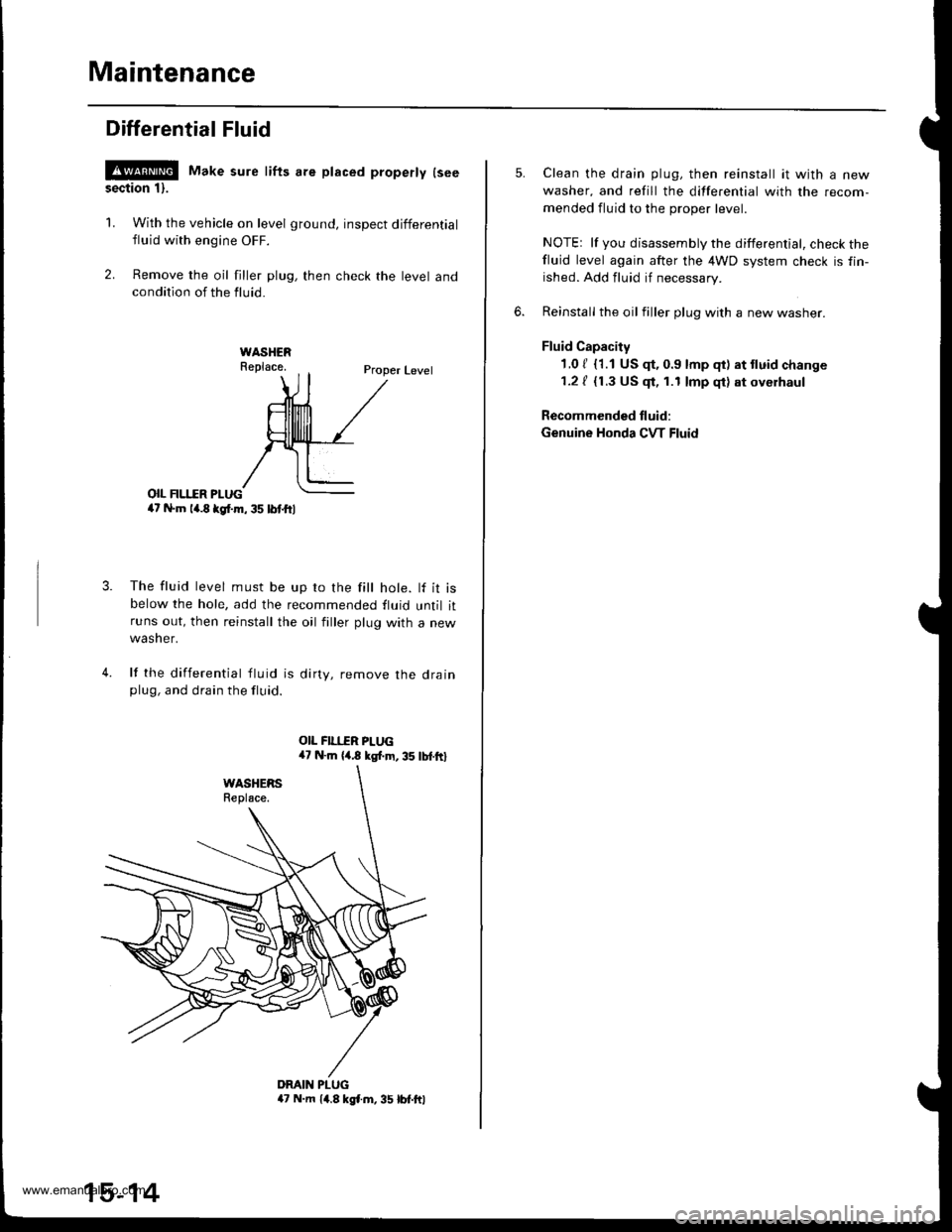
Differential Fluid
!@ Make sure lifts are placed properly lseesection 1).
1. With the vehicle on level ground, inspect differential
fluid with engine OFF.
2. Remove the oil filler plug, then check the level andcondition of the fluid.
Proper Level
o|I FII.IIR PI-UG4t N.m la.8 kgl.m, 35 lbl.ftl
The fluid level must be up ro the fill hole. lf it isbelow the hole, add the recommended fluid until itruns out, then reinstall the oil filler plug with a new
wasner.
lf the differential tluid is dirty, remove the drainplug, and drain the fluid.
4.
DMIN PLUGa7 N.m 14.8 kgl.m, 35 lbt.ftl
15-14
Clean the drain plug, then reinstall it with a new
washer, and refill the differential with the recom-
mended fluid to the proper level.
NOTEr lf you disassembly the differential, check thefluid level again after the 4WD system check is fin-
ished. Add fluid if necessary.
Reinstall the oil filler plug with a new washer.
Fluid Capacity
1.0 / {1.1 US $, 0.9 lmp qt) at tluid change
1.2 / {1.3 US $, 1.1 lmp qt) at oyerhaul
Recommended fluid:
Genuine Honda CVT Fluid
www.emanualpro.com
Page 806 of 1395
Rear Differential Assembly
Removal/lnstallation
l!!@ Make sure tifts are ptaced property lseesection 11.
1. Drain the differential flujd (see page 15-14).
2. Mark the propeller shaft and companion flange of
the rear differential assembly so they can be rein-
stalled in their original positions.
PROPELLER SHAFTCOMPA'{ION FLANGE
Remove the propeller shaft from the rear differential
assemory.
Remove the rear differential damper.
12 POtt'lT BOLI8 x 1.25 mm32 N.m 13.3 tgf.m. 2a lbtft,
Mark
12 x 1.25 mm
15-16
5,1 N.m 15,5 kgf.m, iO tbf.fO
5, Place a transmission jack under the rear differential
assembly, then remove the right mounting bracket B
and the left mounting bracket 8.
Remove the breather tube from the breather tubefitting.
BREATHER TUBE flTNNG
www.emanualpro.com
Page 812 of 1395
Rear Differential Assembly
Disassembly (cont'dl
9. Remove the shim and the clutch quide.
d"HIM'30mm
CLUTCH GUIDE
Remove the clutch hub/plates/discs and the pressure
prare.
10.
CLUTCH HUB/PLATES/OISCS
k
ffi-:*
_zz PRESSURE PLArE
@-
15-22
11. Remove the thrust needle bearing and the oil pump
driveshaft.
Remove the oil pump body assembly, the oil pump
pin, the magnet, and the oil strainer.
OIL PUMP BODY ASSEMBLY
MAGNET
OIL PUMP PIN
12.
OIL STRAINERInspect for damageor clogging.
www.emanualpro.com
Page 813 of 1395
Reassembly
1. Apply CVT fluid to the rubber of the oil strainer, then
install the oil strainer, the magnet, and the oil pump
pin to the differential carrier.
OIL PUMP PIN
DIFFERE]TTIAL CARRIERASSEMBLY
Align the oil pump pin with the groove of the rear oil
pump in the pump body assembly, then install the oil
pump body assembly to the differential carrier assem-
oty.
-n
CWfluid
2.
MAGNET
OIL PUMP BODY ASSEMBLY
3. Tighten the oil pump body assembly mounting
bolts.
4. Install the oil pump driveshaft by aligning the pro-
jection of the oil pump driveshaft with the groove of
the front oil pump in the oil pump body assembly.
lnstall in this direction.
Projection
6x1.0mm12 N.m 11.2 kg{.m,8.7 lbl.ft}
Install the thrust needle bearing.
Install the pressure plate assembly by aligning the
projection of the pressure plate with the groove of
the oil pump driveshaft.
5.
OIL PUMPDRIVESHAFT
(cont'd )
15-23
THRUST NEEDLE BEABING
PRESSURE PLATE
www.emanualpro.com
Page 814 of 1395

Rear Differential Assembly
Reassembly (cont'dl
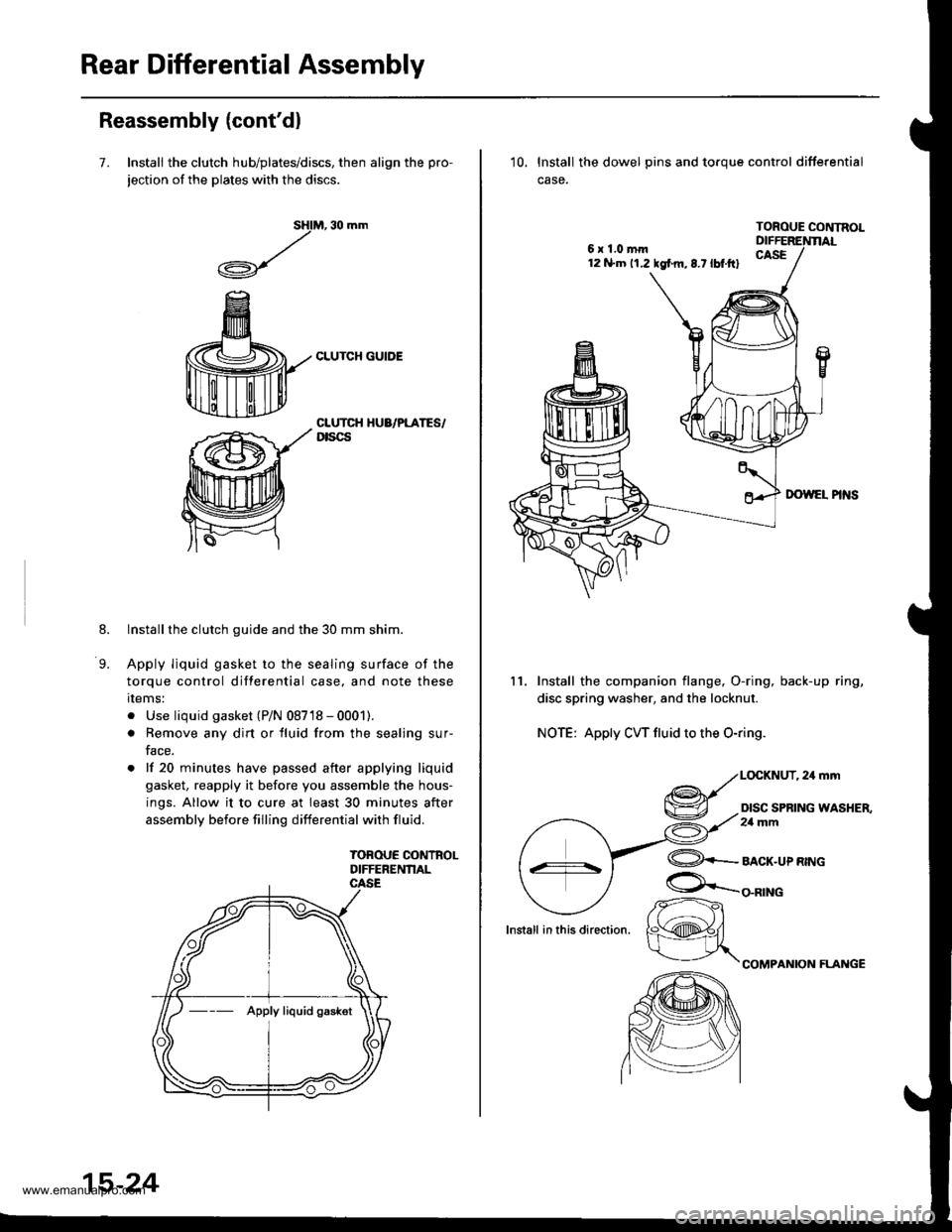
7. Install the clutch hub/plates/discs, then align the pro-
jection of the plates with the discs.
M, 30 mm
CLUTCH GUIDE
sHl
,/
.A-\,/r\-7
8.
9.
CLUTCH HUA/PLATES/Dtscs
Installthe clutch guide and the 30 mm shim.
Apply liquid gasket to the sealing surface of the
torque control differential case, and note these
rlems:
. Use liquid gasket (P/N 08718 - 0001).
. Remove any dirt or fluid from the sealing sur-
face.
. lf 20 minutes have passed after applying liquid
gasket, reapply it before you assemble the hous-
ings. Allow it to cure at least 30 minutes after
assembly before filling differential with fluid.
TOBOUE CONTROLDIFFERENNAL
--- Apply liquid gaskot
15-24
6x1.0mm12 N.m 11.2 tgf m,8.7lbt.ftl
10. lnstall the dowel pins and toroue control differential
case.
TOROUE CONTNOL
11. Install the companion flange, O-ring, back-up ring,
disc spring washer, and the locknut.
NOTE: Apply CW fluid to the O-ring.
,24mm
DISC SPRING WASHER,2a mm
lnstall in this direction.
@+-_alcr-upnwc
COMPANION FLAI{GE
/r-
K@#/
www.emanualpro.com
Page 816 of 1395
Driveshafts
Special Tools .......... ........... 16-2
Driveshafts
Inspection ...................... l6-3
Front Driveshafts
Removal .... 16-3
Disassembly ................... 16-5
Reassembly .................... 16-g
Installation ..................... 16-17
Intermediate Shaft
Removal .... 16-19
Disassembly ................... 16-19
Reassembly .................... 16-20
Installation ..................... 16-21
Rear Driveshafts
Removal .... 16-22
Disassembfy ................... 16-22
Reassembfy .................... 16-24
Installation ..................... 16-29
Propeller Shaft
Inspection . 16-29
RemovaUlnstallation .... 16-30
www.emanualpro.com
Page 818 of 1395

DriveshaftsFront Driveshafts
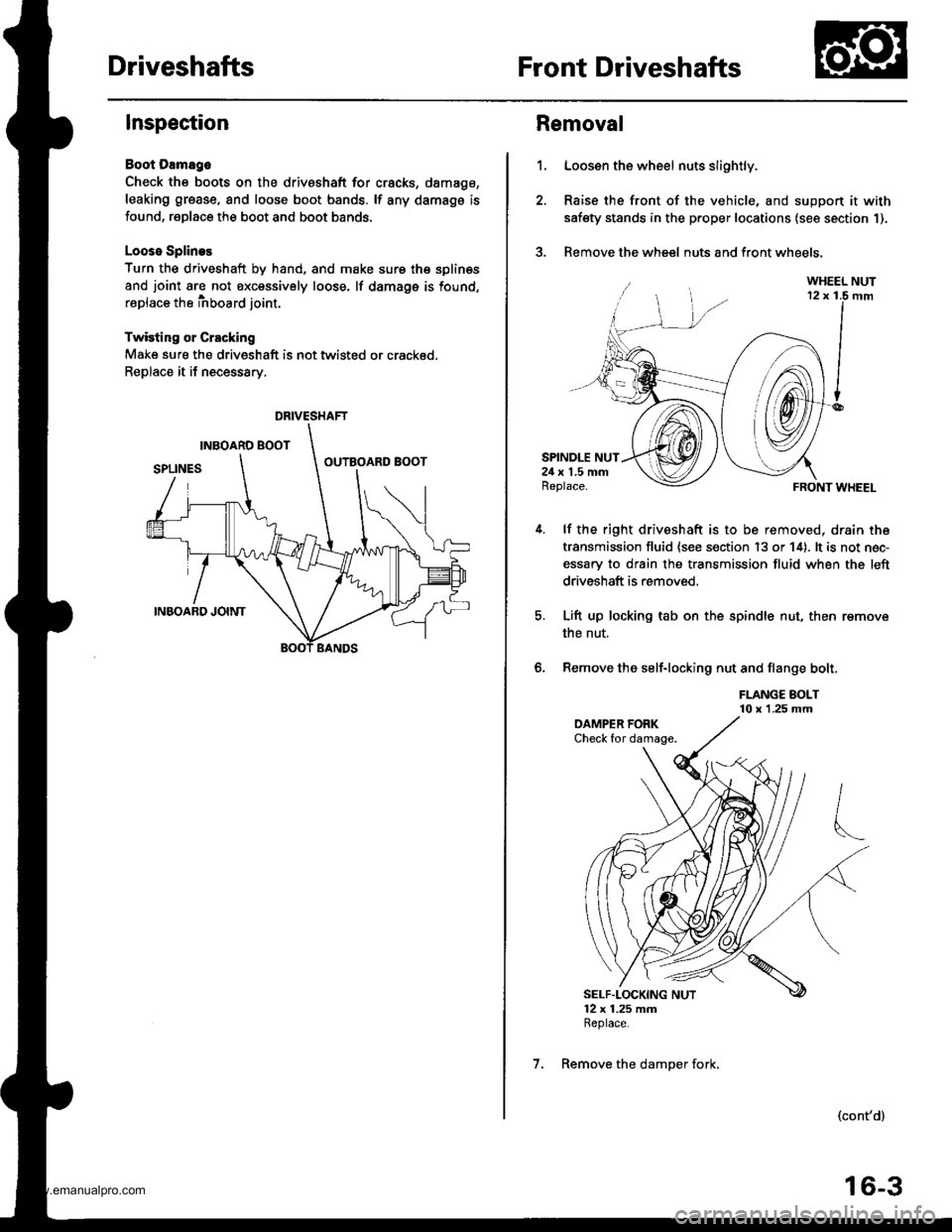
Inspection
Boot Damago
Check the boots on the driveshaft for cracks, damago,
leaking grease, and loose boot bands. lf any damags is
found, replace the boot and boot bands.
Looso Splines
Turn the driveshaft by hand, and make sure th€ splin€s
and joint are not excessively loose. lf damage is found,
replace the inboard joint.
Twisting or Crscking
Make sure the driveshaft is not twisted or crackod.
Replace it if necessary.
DRIVESHAFT
1.
Removal
Loosen the wheel nuts slightly.
Raise the front of the vehicle, and suppon it with
safety stands in the proper locations (see section 1).
Remove the wheel nuts and front wheels.?
SPINDLE NUT24 x 1.5 mmReplace.
lf the right driveshaft is to be removed, drain the
transmission fluid {see s€ction 13 or 14). lt is not nec-
essary to drain the transmission fluid when the left
driveshaft is removed.
Lift up locking tab on the spindle nut, then remove
the nut,
Remove the self-locking nut and flange bolt,
FLANGE BOLT10 x 1.25 mm
FRONT WHEEL
(cont'd)
6.
SELF"LOCKING NUT12 x 1.25 mmReplace.
7. Remove the damper fork,
16-3
www.emanualpro.com
Page 819 of 1395

Front Driveshafts
Removal (cont'd)
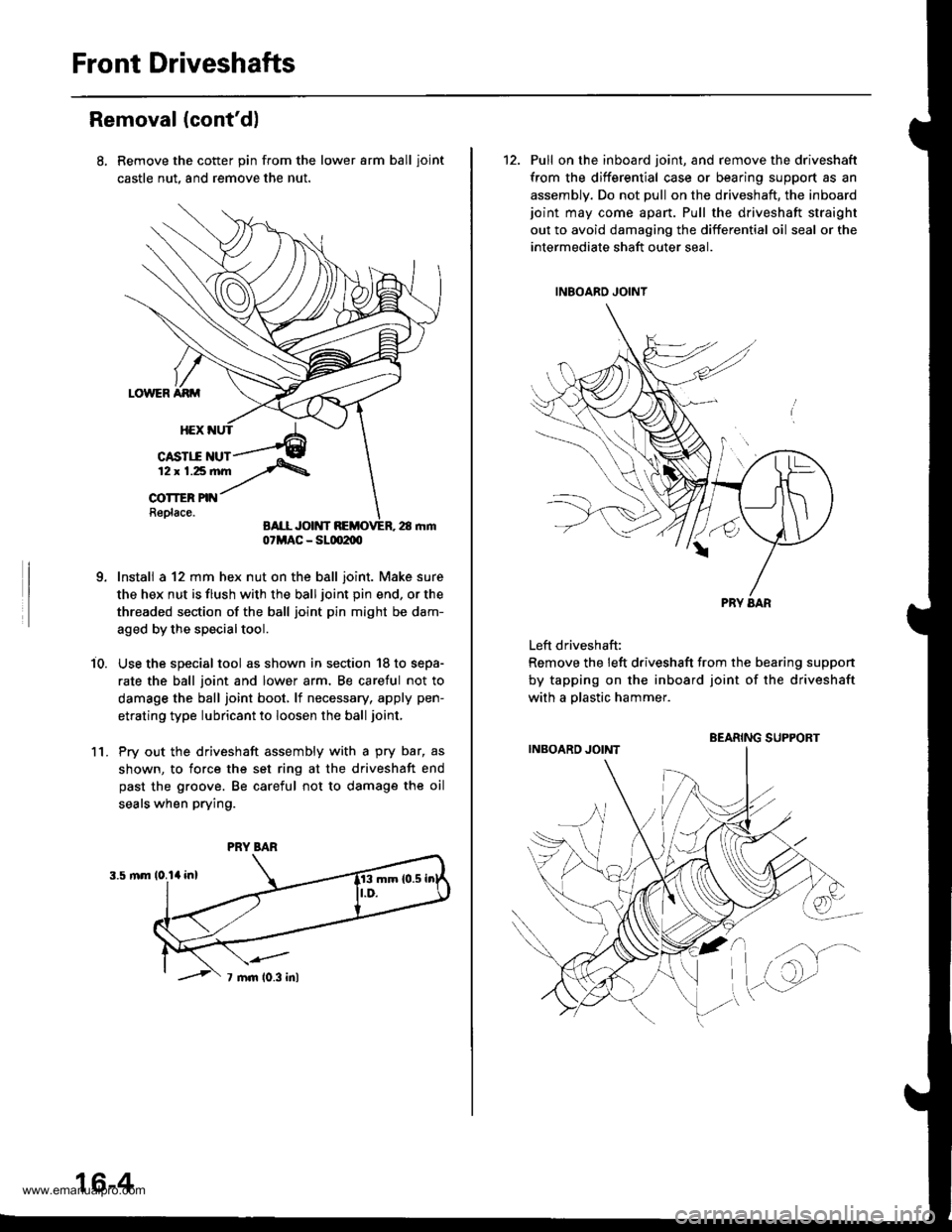
Remove the cotter pin from the lower arm ball ioint
castle nut, and remove the nut.
Install a 12 mm hex nut on the ball joint. Make sure
the hex nut is flush with the ball joint pin end, or the
threaded section of the ball joint pin might be dam-
aged by the special tool.
Use the special tool as shown in section '18 to sepa-
rate the ball joint and lower arm, Be caretul not to
damage the ball joint boot, lf necessary, apply pen-
etrating type lubricant to loosen the ball joint,
Pry out the driveshaft assembly with a pry bar, as
shown, to force the set ring at the driveshaft end
past the groove. Be careful not to damage the oil
seals when prying.
i0.
1l.
07MAC - SLm2m
PRY BAR
16-4
12. Pull on the inboard joint, and remove the driveshaft
from the differential case or bearing support as an
assembly. Do not pull on the driveshaft, the inboardjoint may come apart. Pull the driveshaft straight
out to avoid damaging the differential oil seal or the
intermediate shaft outer seal.
Left driveshaft:
Remove the left driveshaft from the bearing suppon
by tapping on the inboard joint of the driveshaft
with a olastic hammer.
BEARING SUPPORT
www.emanualpro.com