Page 1003 of 1395

Doors
Front and Rear Door Glass
Adiustment (cont'dl
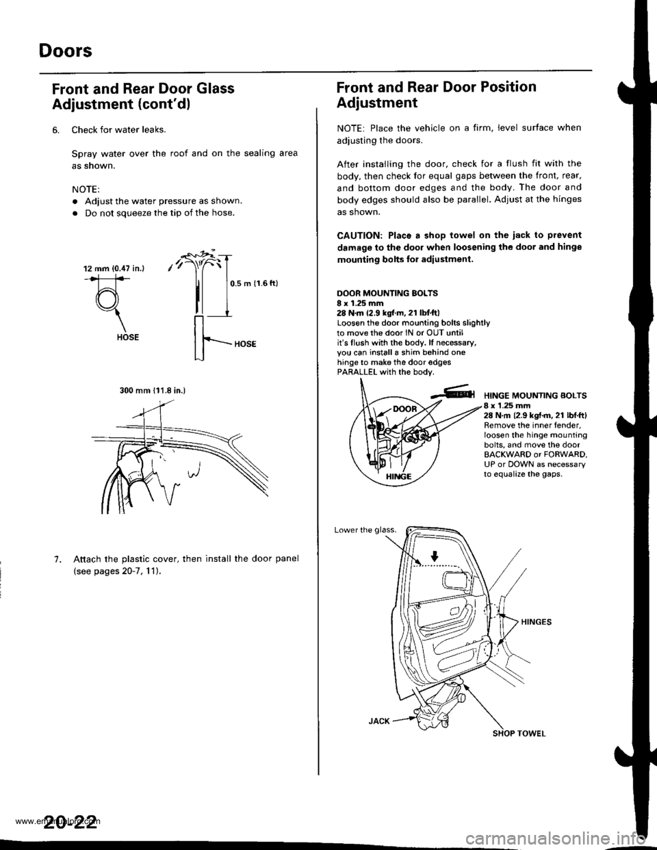
6. Check for water leaks.
Spray water over the roof and on the sealing area
as snown.
NOTE:
. Adjust the water pressure as shown.
. Do not soueeze the tio of the hose.
12 mm {0.47 in.l
#
(r\"1
HOSE
-"'*r"i
,'r)"f
tl
0.5 m (1.6 ftl
7. Attach the plastic cover, then install the door panel
(see pages 20-7, 'l 1),
20-22
..-
300 mm 111.8 in.)
Front and Rear Door Position
Adjustment
NOTE: Place the vehicle on a firm, level surface when
adiusting the doors.
After instailing the door, check for a flush fit with the
body, then check lor equal gaps between the front, rear.
and bottom door edges and the body. The door and
body edges should also be parallel. Adjust at the hinges
as shown.
CAUTION: Placa a shop towel on the iack to prevent
damage to the door when loosening the door and hinge
mounting bolts lor adiustment.
DOOR MOUNTING BOLTSI x 1.25 mm28 N.m 12.9 kgtr.m, 21 lbI.ftlLoosen the door mounting bolrs slighrlyto movethe door lN or OUT untilit's flush with the bodv. lf necessary,you can installa shim behind onehinge to make the door edgesPARALLEL with the bodv.
HINGE MOUNTING BOLTS8 x 1.25 mm28 N,m 12.9 kgt.m. 21 lbl.ftlRemove the inner fender,loosen the hinge mountingbolts, and move the doorBACKWARD or FORWARD,UP or DOWN as necessaryto equalize the gaps.
Lower the glass.
www.emanualpro.com
Page 1004 of 1395
The door and body edges should be parallel. lf neces-
sary, adjust the door cushion.
ry.DOOR CUSHION
Check for water leaks.
NOTE: Do not squeeze the tip ofthe hose.
oooR cusHroNs
Tailgate Door Position Adjustment
NOTE: Place the vehicle on a firm, level surface when
adjusting the tailgate door.
After installing the tailgate door. check for a flush fit
with the body, then check for equal gaps between the
tailgate door edges and the body. The tailgate door and
body edges should also be parallel. Adjust at the hinges
as snown.
CAUTION: Place a shop towel on the iack lo prevent
damage to the tailgale door when loos€ning the tail-
gate door and hinge mounting bolts for adiustment.
TAILGATEDOORMOUNTING sOLTS8 x 1.25 mm25 N.m {2.6 kgf.m,19 tbf.ft)
HINGE MOUNYINGBOLTS8 x 1.25 mm25 N.m 12.6 kgt m,19 rbf.ftl
8x1.0mm22 N'rrl� 12.2 kgl.m,16 tbt.ftl
6xl.0mm9.8 N.m {1.0 kgt m,1.2 tbl.ltl
(cont'd)
20-23
www.emanualpro.com
Page 1225 of 1395
< - ELK/WHT
S'TARTEBCUTRELAY
A,/rGEARPOSrr 0N SWTTCH(CLOSED :ln postion Eor N)
COMBINATONLIGHT SWITCH
\-/
IRED/GRN
I
.l-
NTEGRATED CONTROL UNIT
POWERDOOR LOCKCONTROL UNIT
I B1o PowERBLU/RED DOOR LOCK
I CONTFOL UN T
IY
F r,r'tro J
BLUi RED
"l\
u/
llon. no*
155,1'*IaCLOSED Keylnseded
| \oPEN Key rcmoved
8LK
4
G40r
LTGRN/RED LTGRN/RED LTtl
/rh d[)v !s-l
I FFONT I LEFTI PASSENGEBS I REABI DOOR | 00ORoDen ) lSwlTcH I SWITCHdosedJ J f C-OSED : ooot ooer ) | f CLOSED : Door opel
| ( ooE Doot dosed,r | \oPEN Doo' closed
tl_L -._:-
1,,,,,"
Yilei'rGRN/RED
. BNAKE FLUIOLEVEL SWITCH.PARKING ERAKEswrTcH (usA)
A8
BRAKE BULBCHECKCIFCUTKEY.IN]SEAT BELT and LIGHTS'ONREMINDER C RCU T
23-65
www.emanualpro.com
Page 1241 of 1395

Adjustment
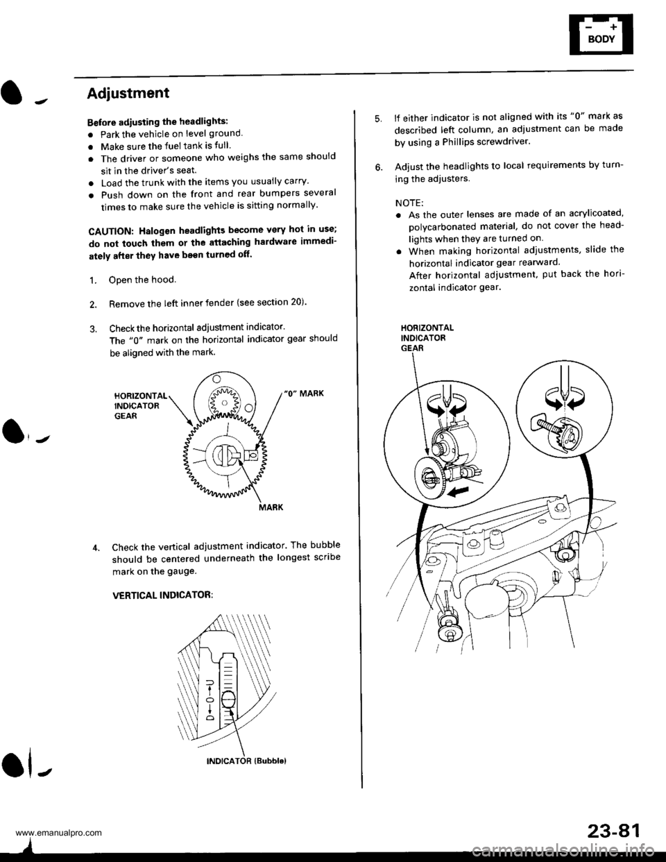
Bstore adiusting the headlights:
. Park the vehicle on level ground
. Make sure the fuel tank is tull
. The driver or someone who weighs the same should
sit in the driver's seat.
. Load the trunk with the items you usually carry'
. Push down on the front and rear bumpers several
times to make sure the vehicle is sitting normally'
CAUTION: Halogen headlights become very hot in use;
do not touch them or the atiaching hardware immedi-
ately after they have been turned off.
1. ODen the hood.
2. Remove the left inner fender {see section 20).
3. Checkthe horizontal adjustment indicator.
The "0" mark on the horizontal indicator gear should
be aligned with the mark.
"0" MARK
Check the vertical adjustment indicator. The bubble
should be centered underneath the longest scribe
mark on the gauge.
VERTICAL INDICATOR:
ol-
)
5.lf either indicator is not aligned with its "0" mark as
described left column, an adjustment can be made
by using a Phillips screwdriver.
Adjust the headlights to local requirements by turn-
ing the adjusters.
NOTE:
. As the outer lenses are made of an acrylicoated,
polycarbonated material, do not cover the head-
lights when they are turned on
. When making horizontal adiustments, slide the
horizontal indicator gear rearward.
After horizontal adjustment, put back the hori-
zontal indicator gear.
HORIZONTALINDICATORGEAR
23-A1
www.emanualpro.com