Page 875 of 1395
Power Steering Pump
Reassembly (cont'dl
'18. Coat the O-ring wjth power steering fluid, andinstall it into the grooves in the inlet joint.
FLANGE BOLTS11 N.m 11.1 kgf.m,8 rbf.ft)
'13 x '1.9
Replace.r
E
19.
20.
Install the inlet joint on the pump housing.
Install the pulley as shown below. then loosely
install the pulley nut. Hold the steering pump in avise with soft jaws. Be careful not to damage thepump housing with the jaws of the vise.
17-30
21. Hold the pulley with the speciat toot, and tighten thepulley nut.
Check that the pump turns smoothly by turning thepulley by hand.
www.emanualpro.com
Page 1145 of 1395
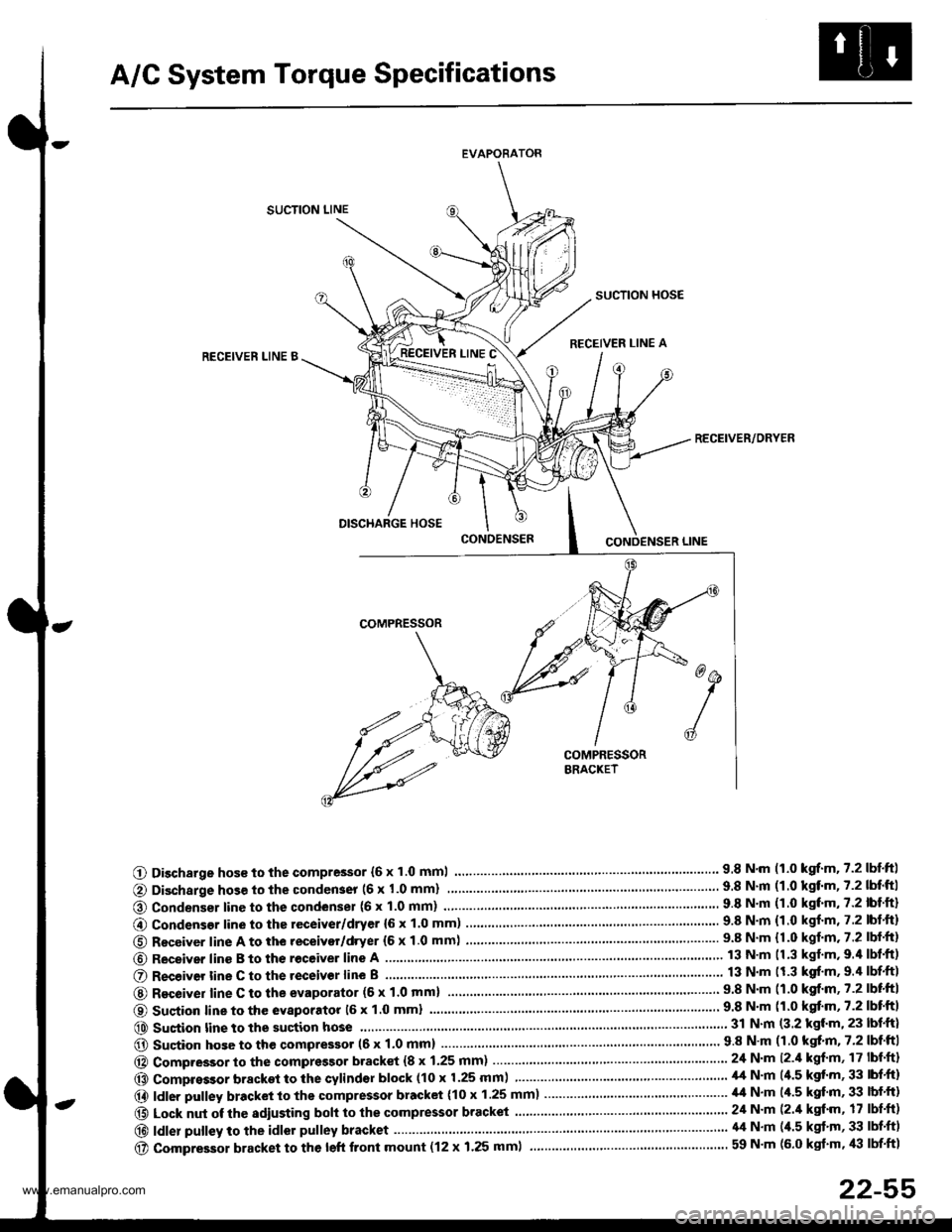
A/C System Torque Specifications
EVAPORATOR
SUCTION LINE
SUCTION HOSE
RECEIVER LINE ARECEIVEN LINE B
RECEIVER/ORYER
O Discharge hos€ to the compressor {6 x 1.0 mml.... 9.8 N.m 11.0 kgrf.m.7.2lbtftl
@ Condenser line to the condenser (6 x 1.0 mm)
@ Condensor line to the receiver/dryer {6 x 1.0 mm) ........9.8 N.m {1.0 kgf.m, 7.2 lbt.ft)
O Receiver line A to the receivor/dryer (6 x 1.0 mm) ...... ....................... 9.8 N.m {1.0 kgf.m.7.2 lbf.ft}
@ Receiver line B to th€ receive. line A
O R€ceiver tine C to the receivor line B
@ Recoiver line C to the evaporator (6 x 1'0 mml9.8 N'm (1.0 kgf.m,7.2lbtftl
O Sustion line to the evaporatot 16 x 1.0 mml
@ Sustion line to the suction hose...... 31 N.m (3.2 kgl.m, 23 lbf.ft)
@ Sucion hose to the qompressor (6 x 1.0 mm) .....'...' 9 8 N'm (1 0 kgt'm, 7'2 lbf'ftI
@ Compressor to the compressor bracket {8 x 1.25 mm) ... 24 N.m l2.il kgf'm, 17 lbf'ft}
@ Compressor bracket to the cylindsr block (10 x 1.25 mm) ................ ......... il,t N'm (4.5 kgt'm, 33 lbf'ft)
@ ldler pulley bracket to the compressor bracket (10 x 1.25 mm)..................... ,14 N.m (/r.5 kgf'm, 33 lbf'ft)
@ Lock nut of the sdiusting boh to the compressor bracket ......................... 24 N'm (2./t kgt'm, 17 lbf'ft)
@|d|erpu||eytotheid|orpu||eybracket.....'..........................'....\
.'.....'........'....44N.m(4.5kg''m'33|bf.f)
@ compressor bracket to the left front mount (12 x 1.25 mml ................... ............................ 59 N'm (6.0 kgt'm, /l:| lbf'ft1
22-55
www.emanualpro.com
Page 1152 of 1395
Compressor
Replacement
lf the compressor is marginally operable. run the
engine at idie speed, and let the air conditioner
work for a few minutes. then shut the engine off.
Disconnect the negative cable from the battery.
Recover the refrigerant with a recovery/recycling/
charging station (see page 22-59).
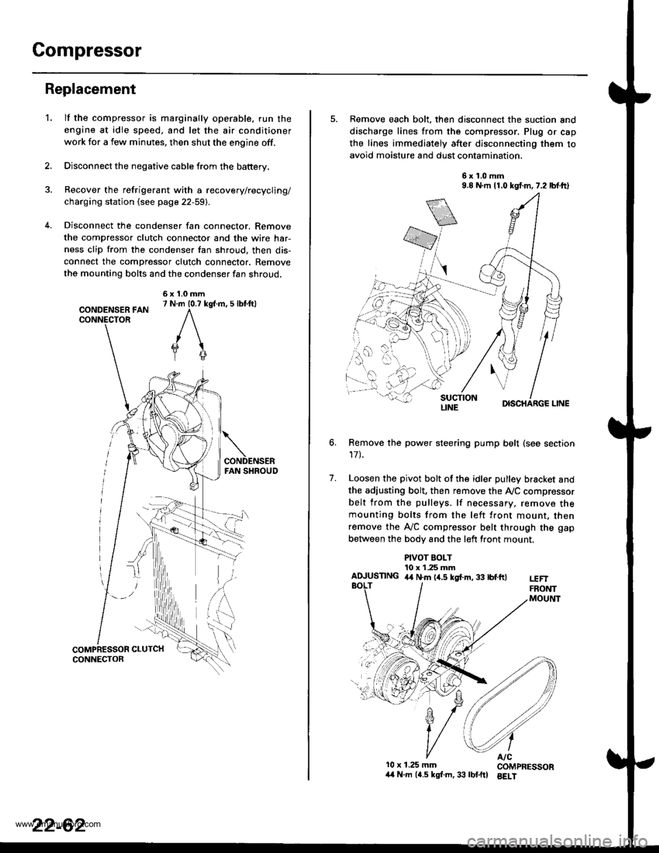
Disconnect the condenser fan connector. Remove
the compressor clutch connector and the wire har-
ness clip from the condenser fan shroud, then dis-
connect the compressor clutch connector. Remove
the mounting bolts and the condenser fan shroud,
CONDENSER FANCONNECTOR
6x1.0mm7 N.m 10.7 kg{.m, 5 lbl.ftl
'L
2.
5. Remove each bolt, then disconnect the suction and
discharge lines from the compressor. Plug or cap
the lines immediately after disconnecting them to
avoid moisture and dust contamination,
6x1.0mm9.8 N.m 11.0 kgf.m,7.2 lbf.ft)
DISCHARGE LINE
Remove the power steering pump belt (see section
17t.
Loosen the pivot bolt of the idler pulley bracket and
the adiusting bolt, then remove the Ay'C compressor
belt from the pulleys. lf necessary, remove themounting bolts from the left front mount, thenremove the A,/C compressor belt through the gap
between the bodv and the left front mount.
6.
7.
PIVOT BOLT10 x 1.25 mmAIUUSTING 4,t N.m (4.5 kgf.m, 33 tbf.ftlt€FTFRONTMOUltlT
10x 1.25 mm COMPRESSOR/t4 N.m (4.5 kgl.m,33 lbtftl BELI
LINE
www.emanualpro.com
Page 1153 of 1395
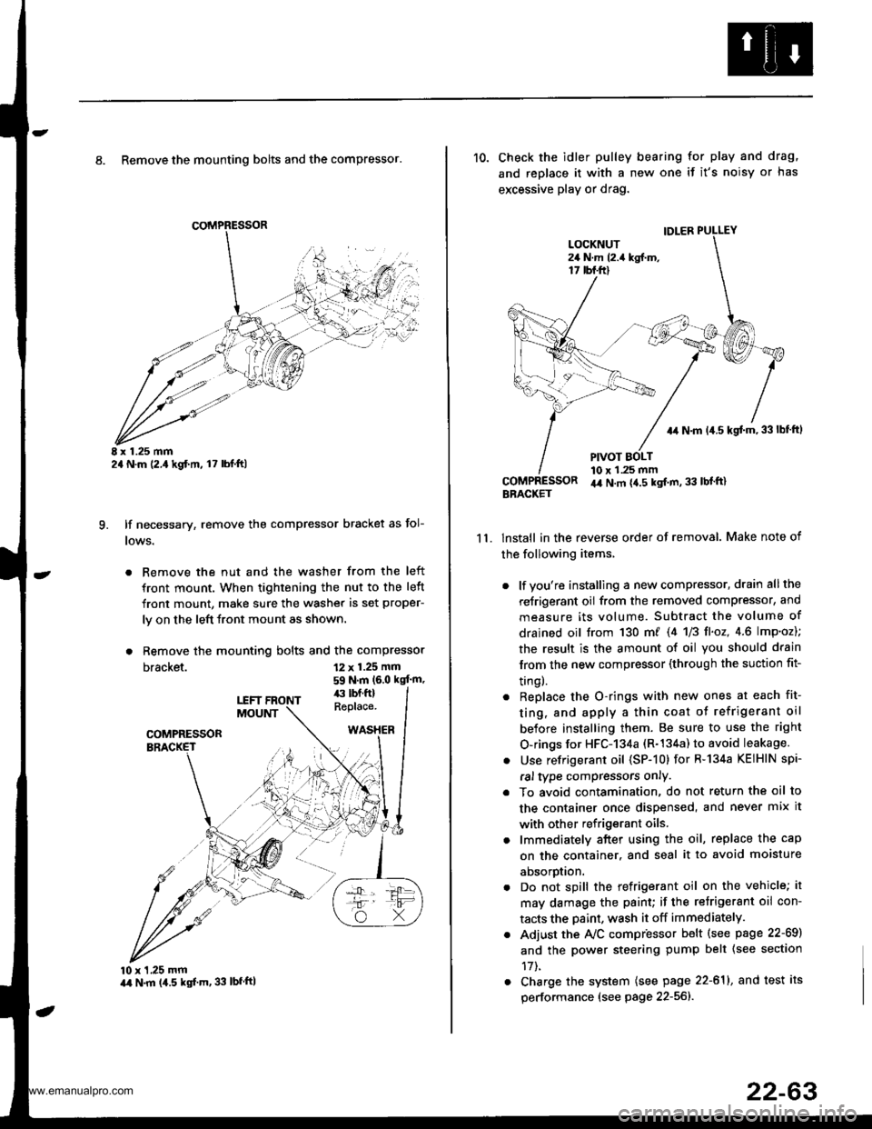
8. Remove the mounting bolts and the compressor.
E x 1.25 mm2a N.m (2.,1kgf.m, l7 lbl.ft)
lf necessary, remove the compressor bracket as fol-
lows.
. Remove the nut and the washer from the left
front mount. When tightening the nut to the left
front mount, make sure the washer is set proper-
ly on the left front mount as shown.
. Remove the mounting bolts and the compressor
bracket.
q
12 x 1.25 mm
59 N.m (6.0 kgt'm,
10 x 1,25 mmart N.m (4.5 kgf'm, 33 lbfftl
11.
10. Check the idler pulley bearing for play and drag,
and replace it with a new one if it's noisy or has
excessive play or drag.
lnstall in the reverse order of removal. Make note of
the following items,
. lf you're installing a new compressor, drain all the
reJrigerant oil from the removed compressor, and
measure its volume. Subtract the volume of
drained oil trom 130 m/ 14 U3 fl'o2,4.6 lmp'oz);
the result is the amount of oil you should drain
lrom the new compressor (through the suction fit-
trngl.
. Replace the O-rings with new ones at each fit-
ting, and apply a thin coat o{ refrigerant oil
before installing them. Be sure to use the right
O-rings for HFC-134a (R-134a) to avoid leakage.
. Use refrigerant oil (SP-10) for R-134a KEIHIN spi-
ral type compressors only.
. To avoid contamination, do not return the oil to
the container once dispensed, and never mix it
with other refrigerant oils.
. lmmediately after using the oil, replace the cap
on the container. and seal it to avoid moisture
aDsorprlon.
. Do not spill the refrigerant oil on the vehicle; it
may damage the paint; if the retrigerant oil con-
tacts the Daint, wash it off immediately.
. Adjust the Ay'C compr'essor b€lt (see psge 22-69)
and the power steering pump belt {see section
17t.
. Charge the system (see page 22-611, and test its
performance (see page 22-56]-.
IDLER PULLEY
+r N.m 14.5 kgt m,33lbf ftl
PIVOT BOLT10 x 1.25 mmir4 N.m {4.5 kgt m, 33 lbl'ft}BBACKET
www.emanualpro.com
Page 1154 of 1395
Gompressor
lllustrated Index
CENTER NUTReplace.
ARMATURE PLATEInspection, page 22-65
sHtM{s)Replace.
SNAP RING BReplace.
ROTOR PULLEYInspection. page 22-65
SNAP RING AReplace.
FIELD COILInspection, page 22-65
THERMAL PROTECTORReplace.Inspection, page 22-55Replacement, page 22-68
coMPRESSOR ----------------(Do not disassemble.)
O.RINGRoplace.
RELIEF VALVEReplacement, page 22-68
RELIEF VALVE COVER('97 modelonly.)
22-64
www.emanualpro.com
Page 1155 of 1395
Clutch Inspection
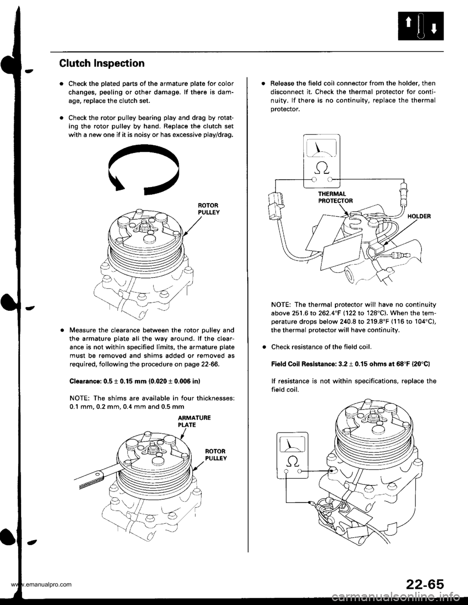
Check the plated parts of the armature plate for color
changes, peeling or other damage. lf there is dam-
age, replace the clutch set.
Check the rotor pulley bearing play and drag by rotat-
ing the rotor pulley by hand. Replace the clutch set
with a new one if it is noisy or has excessive play/drag.
Measure the clearance between the rotor pulley and
the armature plate all the way around. lf the clear-
ance is not within specified limits, the armature plate
must be removed and shims added or removed as
required, following the procedure on page 22-66.
Cloarance: 0.5 t 0.15 mm {0.020 t 0.q)6 in)
NOTE: The shims are available in four thicknesses:
0.1 mm. 0.2 mm. 0.4 mm and 0.5 mm
ABMATUBE
ROTOR
. Release the field coil connector from the holder, then
disconnect it. Check the thermal protector for conti-
nuity, lf there is no continuity, replace the thermal
prorecror.
NOTE: The thermal protector will have no continuity
above 251.6 to 262.4"F 1122 to 128"C). When the tem-perature drops below 240.8 to 219.8"F (116 to 104'C),
the thermal protector will have continuity.
Check resistance of the field coil.
Field Coil Resistance: 3.2 i 0.15 ohms at 68"F {20'C)
lf resistance is not within specifications, replace the
field coil.
22-65
www.emanualpro.com
Page 1156 of 1395
Compressor
Glutch Overhaul
1. Remove the center nut while holding the armature
plate with the tool.
A,/C CLUTCH HOLOERlCommerciallY .vailable)Robinair: P/N 1020,0Ked-Mooro: P/N J37872
CENTER NUT17.6 N.m ('1.8 kgf.m, 13lbfft)Reolace. \
i
2. Remove the armature plate by pulling it up by hand.
ARMATURE PLATE
sHtMls)Replace.
za:s
(i@,
22-66
3. Remove the snap ring B with snap ring pliers. Be
careful not to d8mage the rotor pulley and com-
pressor.
SNAP RING BR6place.
Remove the rotor pulley from the shaft with the
tools. Be sure the claws ot the puller are on the back
of the rotor pulley, not on the belt area; otherwise
the rotor pulley can be damaged.
www.emanualpro.com
Page 1157 of 1395
l-
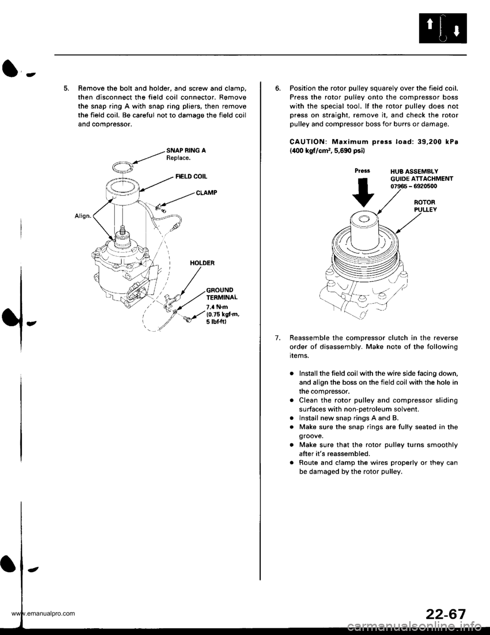
5. Remove the bolt and holder, and screw and clamp.
then disconnect the field coil connector. Remove
the snap ring A with snap ring pliers, then remove
the field coil. Be careful not to damage the field coil
and comoressor.
FIELD COIL
CLAMP
HOLDER
GROUNDTERMINAL
7,a N.m
10.75 kgt'm,5 tbt ftl
6. Position the rotor pulley squarely over the field coil.
Press the rotor pulley onto the compressor boss
with the special tool. lf the rotor pulley does not
press on straight, remove it, and check the rotor
pulley and compressor boss for burrs or damage.
CAUTION: Maximum pre3s load: 39,200 kPa
(400 kgf/cm,, 5,690 psi)
Press
+
HUB ASSEMBLYGUIDE ATTACHMENT07966 - 6920500
7.
ROTORPULLEY
Reassemble the comDressor clutch in the reverse
order of disassembly. Make note of the following
rrems.
Install the field coil with the wire side facing down,
and align the boss on the tield coil with the hole in
the compressor.
Clean the rotor pulley and compressor sliding
surfaces with non-oetroleum solvent.
lnstall new snap rings A and B.
Make sure the snap rings are fully seated in the
groove.
Make sure that the rotor pulley turns smoothly
after it's reassembled.
Route and clamp the wires properly or they can
be damaged by the rotor pulley.
a
a
www.emanualpro.com