Page 199 of 1395
Inspection
1.
2.
Remove the timing belt (see section 6)
Turn the water pump pulley counterclockwise.
Check that it turns freely.
Check for signs of seal leakage.
NOTE: A small amount ol "weeping" from the bleed
hole is normal.
BIIED HOLE
Replacement
1. Remove the timing belt (see section 6).
2. Remove the water pump by removing five bolts
3, Inspect, repair and clean the O-ring groove and the
mating surface with the cylinder block.
Replace.6x1.0mm't2 N.m 11 2 kgf m.
8.7 tbf.ftl
4. lnstall the water pump in the reverse order of removal.
-
@-
I
I
10-1 1
www.emanualpro.com
Page 688 of 1395
Transmission
21.
Removal (cont'dl
Make reference marks across the transfer assemblv
and propeller shaft flanges. (4WD)
Separate the propeller shaft from the transfer
assembly. (4WD)
I x 1.25 mmReplace.
Remove the intermediate shaft,
Tie plastic bags over the both ends of the intermedi-
ate shaft. Coat all precision finished surfaces with
clean engine oil.
22.
REFERENCE MARKS
14-172
24.Remove the right front mounvbracket.
Remove the ATF cooler hoses at the ATF cooler
lines. Turn the ends of the cooler hoses uo to ore-
vent ATF from flowing out, then plug the lines and
hoses. Check for any sign of leakage at the hose
ioints.
RIGHT FRONTMOUNT/BRACKET
Remove the rear stiffener and torque converter
cover.
Remove the eight drive plate bolts, one at a time.
while rotating the crankshaft pulley.
27.
COVER
DRIVE PLATE
www.emanualpro.com
Page 776 of 1395

Transmission
Installation (cont'dl
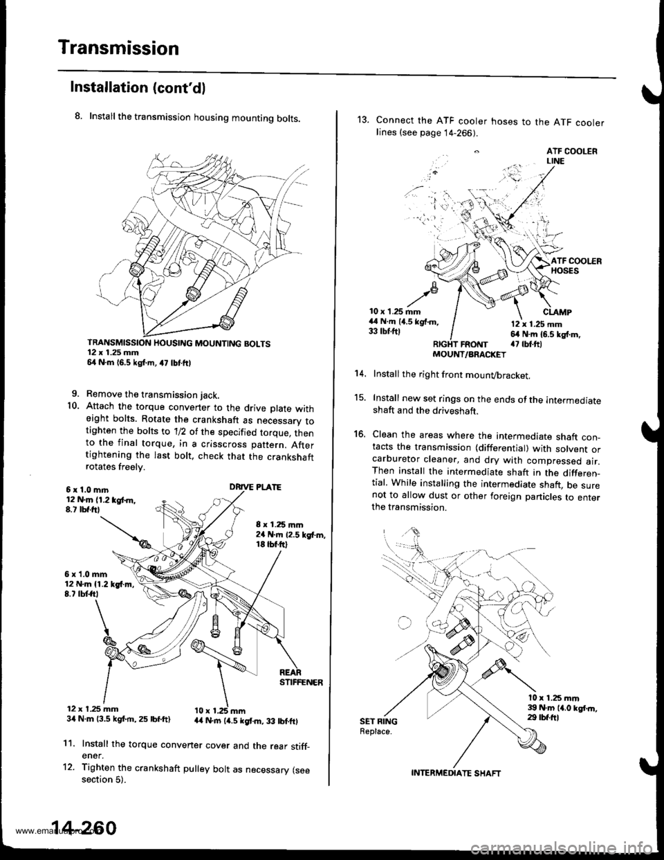
8. Install the transmission housing mounting bolts.
TRANSMISSION HOUSING MOUNTING BOLTS12 x 1.25 mm54 N.m 16,5 kgf.m, a7 lbtftl
9. Remove the transmission jack.
10. Attach the torque convener to the drive plate witheight bolts. Rotate the crankshaft as necessarv totighten the bolts to 'll2 of the specified torque, thento the final torque, in a crisscross pattern. Aftertightening the last bolt. check that the crankshaftrotates freelv.
6x1.0mln12 N.m (1.2 tgt m,8.t lbf.frl
6x1.0mm12 N.m {1.219{.m,8.7 tbtft,
12 x t.25 mm34 N.m 13.5 kgf.rn,25 lbf.ft)
8 x 1.25 mm2a N.m 12.5 kgf'm,18 tbt.ftl
DRIVE PLATE
STIFFENER
44 N.rn (4.5 kgt m, 33 lbtftl
11.
12.
Install the torque convener cover and the rear stiff_ener.
Tighten the crankshaft pulley bolt as necessary (seesection 5).
14-260
13. Connect the ATF cooler hoses to the ATF coolerlines (see page 14-266).
. ATF COOLERLINE
'i 'l'r',:,.) -
10 x 1.25 mm44 N.m (4.5 kgf.m,33 tbtftl
CLAMP
12 x 1.25 mm64 N.m 16.5 kg{.m,a7 tbt.ftlFRotrtT
15.
16.
't 4.
SET RINGReplace.
MOUNT/ARACKET
Install the right front mounvbracket.
Install new set rings on the ends of the intermediateshaft and the driveshaft.
Clean the areas where the intermediate shaft con_tacts the transmission {differential) with solvent orcarburetor cleaner, and dry with compressed air.Then install the intermediate shaft in the differen_tial, While installing the intermediate shaft, be surenot to allow dust or other foreign panicles to enterthe transmission.
l0 x 1.25 mm39 N.m 14.0 kgt.n,29 tbf.ftl
INTERMEDIATE SHAFT
www.emanualpro.com
Page 852 of 1395

Uneven or rough steering.Ad,ust the rack gu ide (see page 17- 15).
ll the problem is not corrected byadjusting the rack guide, replacethe gearbox.
Adjust the belttension. Replace thebelt, if necessary (see page 17-14).Belt slipping on pulley.
lf the engine stalls when thewheel is turned while the vehicleis stopped or moving at lowspeed, adjust the idle speed (seesection 111.
ldle speed low or erratic.
Check power steering lluid level. lfthe level is excessively low checkfor leaks in the system. Add fluidto the specified level.
Air in reservoir, or check powersteering tluid level.
lf fluid level is OK, check O-ringsand seals on both ends of thepump inlet hose, and the P/Spump housing mating surlacesand drive shaft oil seal for suction leaks. Check the reservoir forcracks, Replace parts as neces-
Pump belt slipping on pulley(pump stops momentarily).Adjust the belt tension (see page17-14) or replace belt.
Check if pump pressure is normaland the gauge needle travel is 500kPa (5 kgl/cm,, 71 psi) or less.Check the flow control valve if theneedle travel exceeds 500 kPa (5kgflcm'�, 71 psi). lI the flow controlvalve is normal, replace the pumpas an assembly,
Install the power steering pres-sure gauge, Close the pressurecontrol valve and shut off valve (if
so equipped) fully and measurethe pump pressure (see page 17-16ot 17 17).
Steering wheel kicks backduring wide turns.
7-7
www.emanualpro.com
Page 854 of 1395
Pump noiseGrating nois€trom pump
Pump noise
Raftle or chattering
Check the fluid lev€1.lt low, fill the reservoir to theproper level. and check for leaks.Tighten or roplace as necessary,
Cavitation caused by air bubblesin the fluid.
Check for a crushed inlet hose ora loose hose clamp allowing airinto the suction side of the system. Check the reservoir forcracks. Tighten or replace as nec-
Check the drive shaft oil seal.
Pump noise up to 2 - 3 minutesafter starting in cold weather isnormal, Compare pump noise atoperatrng temperature to anothervehicle.
ll pump noise is abnormally loud,remove and inspect the pump forwear and damage (see page 17-251.
Tighten or replace the pulley.lI shaft is loose, replace thepump.
17-9
www.emanualpro.com
Page 859 of 1395

Inspection and Adjustment
Pump Belt
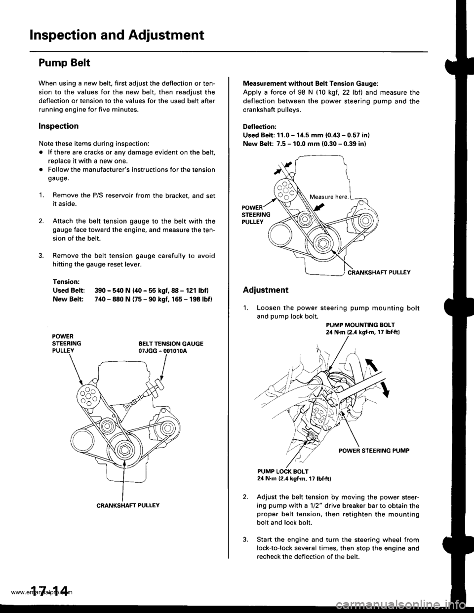
When using a new belt. first adjust the deflection or ten-
sion to the values for the new belt, then readjust the
deflection or tension to the values for the used belt after
running engine for five minutes.
Inspection
Note these items during inspection:
a lf there are cracks or any damage evident on the belt,
replace it with a new one.
. Follow the manufacturer's instructions lor the tension
gauge.
'1. Remove the P/S reservoir from the bracket, and set
it aside.
2. Attach the belt tension gauge to the belt with the
gauge face toward the engine, and measure the ten-
sion of the belt.
Remove the belt tension gauge carefully to avoid
hitting the gauge reset lever.
Tension:
Used Belt: 390 - 540 N {40 - 55 kgf, 88 - 121 lbf)
New Belt: 7,[0 - 840 N (75 - 90 kgf, 165 - 198 lbf)
CRANKSHAFT PULLEY
17-14
Measurement without Belt Tension Gauge:
Apply a force ot 98 N (10 kgf,22 lbt) and measure the
deflection between the power steering pump and the
crankshaft oullevs.
Deflection:
Used Belt: 11.0 - 1i1.5 mm {0.'(l - 0.57 in)
New Belt: 7.5 - 10.0 mm {0.30 - 0.39 in)
CRANKSHAFT PULLEY
Adiustment
'1. Loosen the power steering pump mounting bolt
and pump lock bolt.
PUMP MOUNNNG BOLT24 N'm (2.4 kgf'm, 17 lbf ftl
PUMP LOCK BOLT24 N.m 12.4 kgf.m, 17 lbf.ftl
Adjust the belt tension by moving the power steer-
ing pump with a 1/2" drive breaker bar to obtain theproper belt tension, then retighten the mounting
bolt and lock bolt.
Start the engine and turn the steering wheel from
lock-to-lock several times, then stop the engine and
recheck the deflection of the belt.
Measure here.
www.emanualpro.com
Page 869 of 1395

Power Steering Pump
Replacement
1.Place a suitable container under the vehicle.
Drain the power steering fluid from the reservoir.
Remove the belt by loosening the pump mountingbolt and pump lock bolt.
PUMP MOUNNNG BOI.T24 N.m 12.4 kgt m, 17 lbl.ftl
PUMP LOCK BOLT24 N.m (2.4 kg{.m, 1, tbfttl
Cover the IVC compressor with several shop towelsto protect it from spilled power steering fluid.Disconnect the pump inlet hose and pump outlethose from the pump, and plug them. Take care notto spill the lluid on the body or parts. Wipe off anyspilled fluid at once.
Remove the pump mounting bolt and pump lockbolt, then remove the pump. Do not turn the steer-ing wheelwith the pump removed.
Cover the opening of the pump with a piece of tapeto prevent foreign materialfrom entering the pump.
PUMP OU'I.TT HOSE
11 N.m (1.1 kgf.m,E rbf.ti)
17-24
7.Connect the pump inlet hose and pump outlet hose.Tighten the pump fittings securely.
Loosely install the pump in the pump bracket withthe mounting bolt and lock bolt.
Install the pump belt.
Note these items du.ing belt instsllation:. Make sure that the power steering belt is proper-
ly positioned on the pulleys.
. Do not get power steering fluid or grease on thepower steering belt or pulley faces, Clean off anyfluid or grease before installation
FOWER STEER G EELT
PUTrlY
Adiust the pump belt (see page 17-141.
Fill the reservoir to the upper level line (see page't7 -151..
10.
'l l.
www.emanualpro.com
Page 871 of 1395

Power Steering Pump
Disassembly (cont'dl
1.
7.
9.
10.
Drain the fluid from the pump.
Hold the steering pump in a vise with soft jaws.
hold the pulley with the special tool, and remove
the pulley nut and pulley. Be careful not to damagethe pump housing with the jaws of the vise.
UNIVERSAL HOLDER07725 - 0030000
Loosen the flow control valve cap with a hexwrench, and remove it.
Remove the O,ring, flow control valve and spring.
Remove the inlet joint and O-ring.
Remove the pump cover and pump cover seal.
Remove the outer side plate, pump cam ring, pump
rotor, pump vanes, side plate and O-rings.
Remove the snap ring, then remove the sub-valvefrom the pump housing.
Remove the circlip, then remove the pump driveshaft by tapping the shaft end with the ptastic ham-mer.
Remove the pump seal spacer and pump seal.
17-26
Inspection
Flow Control Valve
1. Check the flow control valve for wear, burrs, and
other damage to the edges of the grooves in thevalve.
'97 model:
FLOWCONTROL VALVE
Check fordamage to edges.
'98 - 0O mod€ls:
FLOW CONTBOL VALVE
Check for damageto edges.
Insp€d the bore of the flow control valve tor scratchesor wear.
Slip the valve back in the pump, and check that itmoves in and out smoothly. lf OK, go to step 4; ifnot, replace the pump as an assembly. The flowcontrolvalve is not available separately.
CONTROL VALVE
4. Attach a hose to the end of the valve as shown.
FLOW CONTROL VALVE HOSE
www.emanualpro.com