Page 873 of 1395
Power Steering Pump
Reassembly
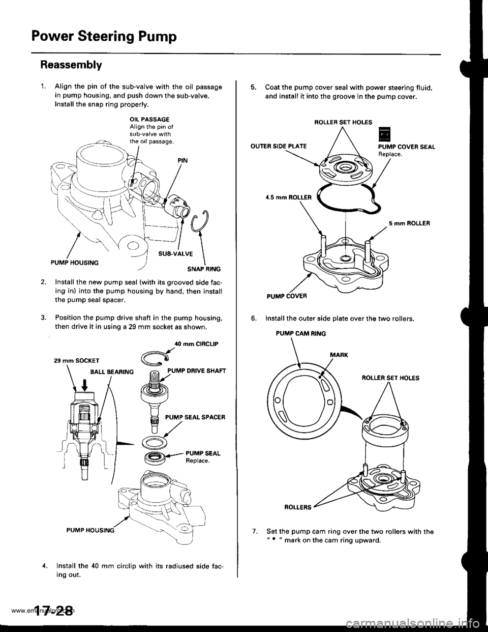
'1.Align the pin of the sub-valve with the oil passage
in pump housing, and push down the sub-valve.
Install the snsp ring properly.
OIL PASSAG€Align the pin of
the oil passage.
#q
;1..*
\SNAP RINGPUMP HOUSING
Install the new pump seal (with its grooved side fac-
ing in) into the pump housing by hand, then install
the pump seal spacer.
Position the pump drive shaft in the pump housing,
then drive it in using a 29 mm socket as shown,
BALL BEARfNG grlu,e un.t
/ /ffi\
1 / t\v4
t/ Y
# I F
PUMP SEALSPAC,ER
ry^
i- d
,O mm CIRCLIP
Hgo
/= PUMP DRIVE SHAFT
@.--#$i":*'
4,
PUMP HOUSING
Install the 40 mm circlip with its radiused side fac-
Ing out.
29 mm SOCKET
17 -2A
7.
5. Coat the pump cover seal with power steering fluid,
and install it into the groove in the pump cover.
OUTER SIDE PLATE
5 mrh ROLLER
lnstall the oute. side plate over the two rollers.
PUMP CAM RING
ROLLER SET HOLES
ROLLERS
Set the pump cam ring over the two rollers with the"' " mark on the cam ring upward.
ROLLER SET HOLES
PUMP COVER
www.emanualpro.com
Page 874 of 1395
8.
9.
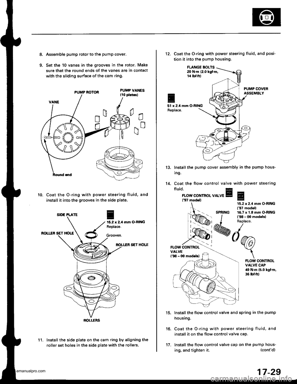
Asssmble pump rotor to the pump cover,
Set the 10 vanes in the grooves in the rotor, Make
sure that the round ends of the vanes are in contact
with the sliding surface of the cam ring.
PUMP ROTOR
Coat the O-ring with power steering fluid, and
install it into the grooves in the side plate.
ftm GRING
ROL1IR SET HOI,E
SET HOTT
Install the side plate on the cam ring by aligning the
roller set holes in the side Dlate with the rollers.
10.
I
15.2 x 2-1Replace.
Gfooves.
SII'E PLATE
BOLI-ERS
11.
17.
ing, and tighten it.
12. Coat the O-ring with power steering fluid,
tion it into the pump housing.
and posi-
FLANGE BOI-TS20 N.m (2.0 kgt m,14 tbf.ft)
51 x 2.4 mm O-RINGReplace.
13.
14.
lnstall the
ing.
Coat the
fluid.
pump cover assembly in the pump hous-
tlow control valve with power steering
FLOW CONTROL VALVE137 modol)
FLOW CONTBOLVALVEl'98 - 0O modeltl
'15.
16.
Install the flow control valve and spring in the pump
housing.
Coat the O-ring with power steering fluid, and
install it on the flow control valve cap.
Install the flow control valve cap on the pump hous-
Eg
SPRING
15.2 x 2.4 mm O.RING('97 modell16.7 x'1.8 mm O-RING
FLOW CONTROLVALVE CAP49 N.m (5.0 kgl.m,36 tbf.ft)
(cont'd)
17-29
www.emanualpro.com
Page 877 of 1395
Power Steering Gearbox
AN'USTABLE HOSE CLAMP
Removal (cont'dl
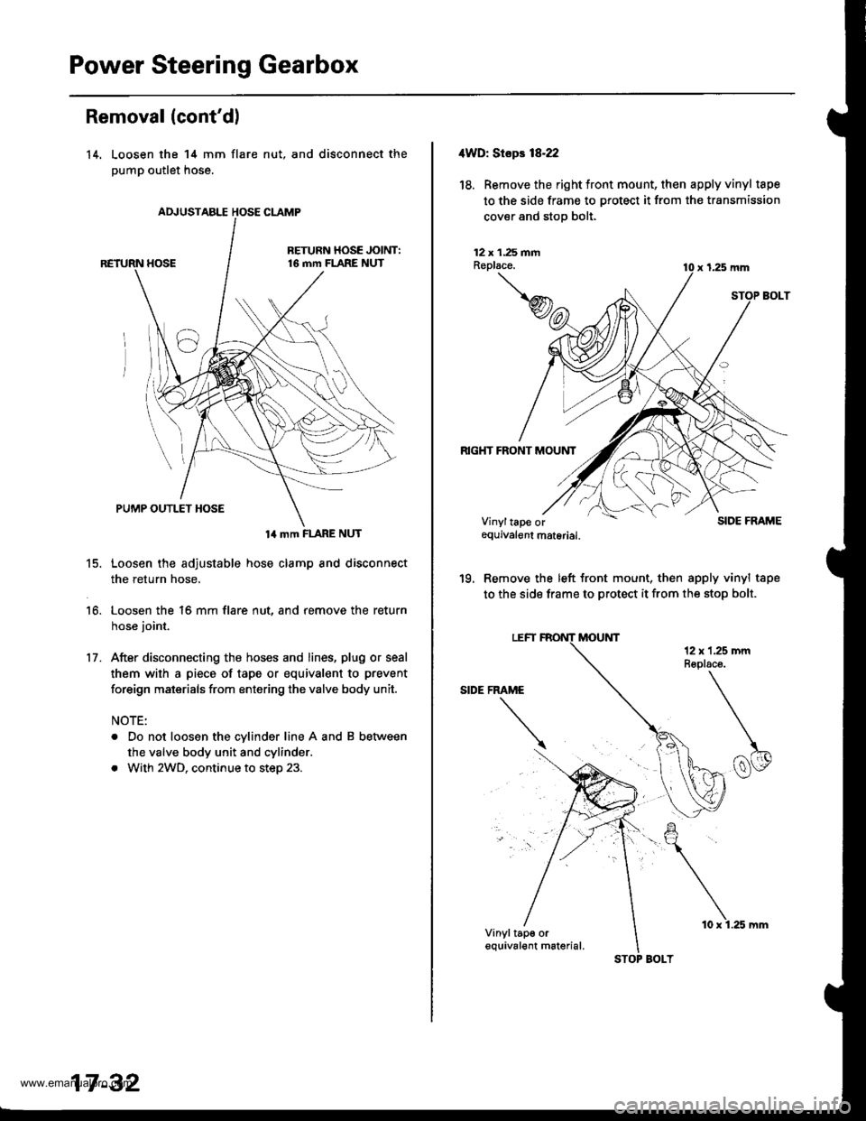
14. Loosen the 14 mm flare
pump outlet hose.
nut, and disconnect the
14 mm FLARE NUT
15. Loosen the adjustable hose clamp and disconnect
the return hose,
16. Loosen the 16 mm flare nut, and remove the return
hose joint.
17. After disconnecting the hoses and lines, plug or seal
them with a piece of tape or equivalent to prevent
foreign maisrials from entering the valve body unit.
NOTE:
. Do not loosen the cylinder line A and B between
the valve body unit and cylinder.
. With 2WD, continue to step 23.
17 -32
STOP BOLT
10 x 1.25 mm
4WD: Stepr 18-22
18. Removethe right tront mount, then apply vinyl tape
to the side frame to protect it from the transmission
cover and stop bolt.
12 x 1.25 fiiAReplace.
RIGHT FRONT MOUNT
x 1,25 mm
SIDE FRAME
'19. Remove the left front mount, then apply vinyl tape
to the side frame to protect it from the stop bolt.
Vinyltape orequivalgnt material.
Vinyltap€ orequival€nt m6terial.
www.emanualpro.com
Page 880 of 1395
5. Hold the steering rack with a wrench {'98 - 00 mod-
els: left end onlv), and unscrew the rack end with
another wrench, Be careful not to damage the rack
surface with the wrench,
LOCK WASHER
Loosen the locknut, then remove the rack guide
screw and O-ring ('97 model).
6.
1.
LOCKNUT
Remove the spring and the rack guide from the gear-
DOX.
RACK GUIDE
9.
8. Remove cylinder lines A and B from the gearbox,
CYLINDER LINE A
Drain the fluid from the cylinder fittings by slowly
moving the steering rack back and {orth.
Remove the two tlange bolts, then remove the valve
body unit from the gearbox. (See page 17-38 for
valve body unit disassembly.)
VINYL TAPE
FLANGE BOLT
Apply vinyl tape to stepped portion of the pinion
shaft, and remove the dust cover.(cont'd)
DUST COVER
11.
17-35
www.emanualpro.com
Page 895 of 1395
Power Steering Gearbox
Reassembly (cont'd)
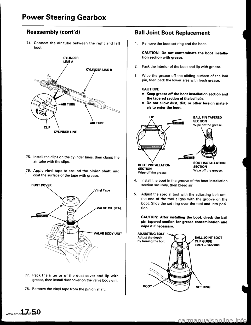
74. Connect the air tube between the right and left
boot,
CYLINDERLINE A
75. Install the clips on the cylinder lines, then clamp theair tube with the clips.
76. Apply vinyl tape to around the pinion shaft, andcoat the surface of the tape with grease.
DUST COVER
Vinyl Tsp€
VALVE OIL SEAL
VALVE BODY UNIT
Pack the interior of the dust cover and lio withgrease, then install dust cover on the valve bodv unit.
Remove the vinyl tape f.om the pinion shaft.
77.
CYLINDER LINE
17-50
SET RING
't.
Ball Joint Boot Replacement
Remove the boot set ring and the boot.
CAUTION: Do not contaminate the boot inslalla-
tion section with graase.
Pack the interior of the boot and lip with grease.
Wipe the grease off the sliding surface of the ballpin. then pack the lower area with fresh grease.
CAUTION:
. Keep grease off the boot installation section and
the tapered section of th€ ball pin.
. Do not allow dust, dirt, or other to.eign materi-
als to enter the boot.
EALL PIN TAPEREDSECTIONWipe olf the grease.
BOOT INSTALLATIONSECTIONWipe offthe grease.
B(X)T IT{STALLATIONsEclroNWipe off the grease.
ADJUSTING BOLTAdiust the depthby turning the bolt.
Install the boot in the groove of the boot installation
section securely. then bleed air.
Adjust the special tool with the adjusting bott untilthe end of the tool aligns with the groove on theboot. Slide the set ring over the tool and into posi-
I|on.
CAUTION: After installing the boot, chock the batlpin lapered section for grease contamination andwipe it it n€cessary.
www.emanualpro.com
Page 937 of 1395

Master Cylinder/Brake Booster
Removal/lnstallation
1, Disconnect the brake fluid level switch connectors.
2. Remove the reservoir cap from the master cylinder.
3. Remove the brake fluid from the master cvlinder
reservoir with a syringe.
4. Disconnect the brake lines from the master cylinder.
To prevent spills, cover the line joints with rags or
shop towels.
5. Remove the master cylinder mounting nuts and
wasners.
6. Remove the master cylinder from the brake booster.
CAUTION: Be careful not to bend or damage the
brake lines when removing the master cylinder.
Do not spill brake fluid on the vehicle; it may dam.
age the paint; it brake fluid does cont.ct the paint,
wash it oft immediately with water.
7. Disconnect the vacuum hose from the brake booster.
8. Remove the cotter pin and clevis pin from the clevis.
Do not disconnect the clevis by removing it from
the operating rod of the brake booster. lf the clevis
is loosened, adjust the pushrod length before
installing the brake booster (see page 19-15).
To Front Caliper (Without ABS)
\\
15 N.m {1.5 kgtm, vAcuuM HosE
r r rbf.ft) |
/ | BRAKE FLUTD LEvEL
/l /
swrrcHcoNNEcroRs
/ I I I COTTER PIN
I I / neotace
l,/-- ro Rear wheet cylinders / | I
h ./-''' /. I I IYli //*s (.S
I /r:
9. Remove the four booster mounting nuts.'10. Pull the brake booster forward until the clevis is
clear of the bulkhead.
11. Remove the brake booster from the enqine com-
panment.
12. Install the brake booster and master cylinder in the
reverse order of removal, and note these items:
. When connecting the brake lines, make sure that
there is no interference between the brake lines
and other parts.
. Be careful not to bend or damage the brake lines
when installing the master cylinder.
. lf replacing the master cylinder or brake booster,
check and adjust the pushrod clearance before
installing the master cylinder (see page 19-14).
Fill the master cylinder reservoir, and bleed the
brake system (see page 19-7).
After installation, check the brake pedal height and
brake pedal free play (see page 19-5), and adjust if
necessary.
13 N.m 11.3 kg{.m,I rbf.ft)
13.
14.
To Master Cylinder(Without ABS)To Modulator Unit(with ABs)@-\
\
^ To Front Caliper
9i\.
-#qCLEVIS PIN
):-,/
PROPORTIONING CONTROL VALVE
MASTER CYLINDER
15 N.m (1.5 kgf.m, 11 lbl.ftl
BRAXE BOOSTER
www.emanualpro.com
Page 1091 of 1395
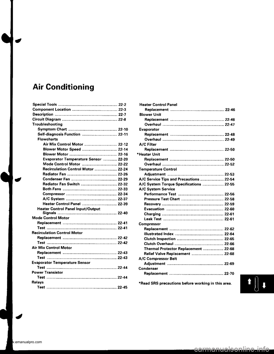
Air Conditioning
Heater Control Panel
Reofacement ,.,...,,.,..,.,.,,22-46
Blower Unit
Replacement .................. 22-46
Overhaul ...........,,,., .......-.22-17
Evaporalor
ReDlacement ...,.,.,..,......,22-4A
Overhaul ................ .........22-19
A/C Filter
Replacement ..................22-50*Heater Unit
ReDfacement ..................22-50
Overhaul ..,.,..,.,...,.. .........22-52
Temperature Control
Adiustment ....................22-53
A/C Service Tips and Precauiions............-....-.... 22-54
A/C System Torque Specifications .................... 22-55
A/C System Service
Performance Test ......,...22-56
Pressure Test Chart .-.....22-5a
Recovery ..............,. ...-.-...22-59
Evacuation -...........-........22-60
Charging ................ .......-.22-61
Leak Test ........................22-61
Compressor
Repfacement ..........-.......22-62
flfustrated Index .....,.......22-64
Cfutch fnspection .........,.22-65
Cfutch Overhaul ............- 22-66
Thermaf Protector Rep|acement ................... 22-68
Refief Valve Replacement .............................. 22-68
A/C Comoressor Belt
Adiustment .................... 22-69
Condenser
Repfacement .,.....,,.,..,.,..22-70
'Read SRS precautions betore working in this area.
www.emanualpro.com
Page 1097 of 1395
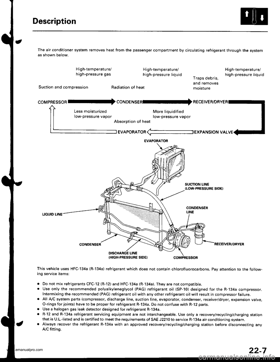
Description
The air conditioner system removes heat from the passenger compartment by circulating refrigerant through the systemas shown below.
High'temperature/ High-temperature/
high-pressure gas h igh-pressure liquid
Suction and compression Radiation of heat
High-temperature/
high-pressu re liq uidr raps oeons,
and removes
motsture
More liquidified
row-pressure vapor
EVAPoRAToR (-l EXPANSToN vAL
SUCTION LINEtLow-PRESSURE S|OEt
LIOUID LINE
CONDENSER
coMpREssoR Il- coruoerusenl* necetve
Less moisturized
low-pressure vapor
Absorption of heat
DISCHARGE LINEIHIGH.PRESSURE SIDEI
This vehicle uses HFC-I34a (R-l34a) refrigerant which does not contain chlorofluorocarbons. Pay attention to the follow-ing service items:
. Do not mix refrigerants CFC-12 (R-12) and HFC-l34a (R-134a). They are not compatible.. Use only the recommended polyalkyleneglycol (PAG) refrigerant oil (SP-10) designed for the R-134a compressor.Intermixing the recommended (PAG) refrigerant oil with any other refrigerant oil will result in compressor failure.. Afl Ay'C system parts (compressor, discharge line. suction line, evaporator, condenser. receiver/dryer, expansion valve,O-rings for joints) have to be proper for refrigerant R-134a. Do not confuse with R-12 parts.
. Use a halogen gas leak detector designed for refrigerant R-134a.. R-12 and R-134a refrigerant servicing equipment are not interchangeable. Use only a recovery/recycling/charging stationthat is U.L.iisted and is certified to meet the requirements of SAE J2210 to service R-134a air conditioning system.. Always recover the refrigerant R-134a with an approved recovery/recycling/charging station before disconnecting anylVC fitting.
EVAPORAYOR
22-7
www.emanualpro.com