Page 757 of 1395
Transfer Gear Bscklash Inspection and Transfer Gear
Tooth Contact Inspection
2. Install the 35 mm thrust shim on the transfer driven
gear shaft, then install the tapered roller bearing
using the special tools and a press.
DRIVER {0 mm LD.077146 - 0030100
TRANSFER DRTVEN ;;.GEAR SHAFT u, 745 - 0O304O0
Place the tapered roller bearing on the bearing outer
race of the companion flange side of the transfer
housrng.
Install the new oil seal on the transfer housing
using the special tools.
OIL SEAL DRIVERATTACHMENT07JAD - PH80101
5. Install the transfer driven gear shaft in the transfer
housing. Do not install the transfer spacer on the
transfer driven gear shaft in this step.
Install the companion flange, conical spring washer,
and locknut on the transfer driven gear shaft. Do
not install the O-ring and the back-up ring on the
transfer gear shaft in this step.
6.
COMPANIONFLANGE
{cont'd)
TRANSFER
TRANSFER HOUSING
14-241
www.emanualpro.com
Page 794 of 1395

Description
Rear Differential
Outline
The Real-time 4WD-Dual Pump System model has a hydraulic clutch and a differential mechanism in the rear differential
assembly. Under normal conditions, the vehicle is driven by the front wheels. However, depending on to the driving force
of the front wheels and the road conditions. the system instantly transmits appropriate driving force to the rear wheels
without requiring the driver to switch between 2WD (tront wheel drive) and 4WD (four wheel drive). The switching mecha-
nism between 2WD and 4WD is integrated into the rear differential assembly to make the system light and compact.
ln addition, the dual-pump system switches off the rear-wheel-drive force when braking in a forward gear. This allows the
braking system to work properly on models equipped with an Anti-lock Braking System (ABS).
Construction
The rear differential assembly consists of the torque control differential case assembly and the rear differential carrier
assembly. The torque control differential case assembly consists of the differential clutch assembly, the companion
flange, and the oil pump body assembly. The rear differential carrier assembly consists of the differential mechanism. The
differential drive and driven gears are hypoid gears.
The oil pump body assembly consists of the front oil pump, the rear oil pump, the hydraulic control mechanism, and the
clutch piston. The clutch piston has a disc spring that constantly provides the differential clutch assembly with a preset
torque to Drevent abnormal sound.
The clutch guide in the differential clutch assembly is connected to the propeller shaft via the companion flange, and it
receives the driving force lrom the transfer assembly. The clutch guide rotates the clutch plate and the front oil pump in
the oil pump body.
The clutch hub in the differential clutch assembly has a clutch disc that is splined with the hypoid drive pinion gear. The
hypoid drive gear drives the rear oil pump.
The front and rear oil pumps are trochoidal pumps. The rear oil pump capacity is 2.5 percent larger that the front oil pump
to handle the rotation difference between the front and rear wheels caused by worn front tires and tight corner braking.
The oil pumps are designed so the fluid intake works as a fluid discharge when the oil pumps rotate in reverse. Genuine
Honda CVT fluid is used instead of differential fluid.
Operation
When there is a difference in rotation speed between the front wheels (clutch guide) and rear wheels (hypoid driven gear),
hydraulic pressure from the front and rear oil pumps engages the differential clutch, and drive force from the transler
assembly is applied to the rear wheels.
The hydraulic pressure control mechanism in the oil pump body selects 4WD mode when the vehicle is started abruptly,
or when accelerating in a forward or reverse gear (causing rotation difference between the front and rear wheels). or
when braking in reverse gear {when decelerating). lt switches to 2WD mode when the vehicle is driven at a constant speed
in forwar! or reverse gear (when there is no rotation difference between the front and rear wheels), or when braking in a
fo rwa rd gear (when decelerating).
To protect the system, the differential clutch assembly is lubricated by hydraulic pressure generated by the oil pumps in
both 4WD and 2WD modes. Also, the thermal switch relieves the hydraulic pressure on the clutch piston and cancels 4WD
mode if the temDerature of the differential fluid rises above normal.
www.emanualpro.com
Page 795 of 1395
TOROUE CONTROL OIFFERENTIAL
REAR DIFFERENTIAL ASSEMBLY
OIL PUMP BODY
OIFFERENTIAL CLUTCHHYPOID DRIVEPINION GEAR
OIFFERENTIAL CARRIER
DIFFERENTIAL
HYPOID RING GEAR
DIFFERENTIAI- HOUSING
REAR OII- PUMP
ASSEMBLY
CLUTCH GUIDE
COMPANION FLANG€
CLUTCH HUB
CLUTCH PLATE
HYDRAULIC CONTROL SYSTEM
CLUTCH PISTON
CLUTCH DISC
REAR OIL PUMP
FRONT OIL PUMP
DISC SPRINGFRONT OIL PUMP
DIFFEREMT|AL CLUTCHASSEMBI-Y
THERMAL SWITCHRELIEF VALVEOIL STRAINER
15-5
www.emanualpro.com
Page 805 of 1395
Rear Differential Assembly
lllustrated Index
O.RINGReplace.
6xl.0m12 N.m (1.2 kgf m,8.7 lbt'ftl
BACK-UP RING
COMPANION FLANGE
CLUTCH HUB/PLATES/DISCS
DIFFERENNAL CLUTCHASSEMBLY
DOWEL PINS
OIL PUMP DRIVESHAFT
LOCKNUT, 24 mmReplace.118 N.m (12.0 kgtm.87 rbt ft)
OIL SEALReplace.
PRESSURE PLATE
THBUST NEEDLEAEARING""t",at\(
'd'
CLUTCH GUIDE
OIL PUMPPIN
e
MAGNET
6x1.0mm12 N.m 11.2 kgt'm,8.7 lbf'ft|
OIL STRAINER
15-15
www.emanualpro.com
Page 807 of 1395

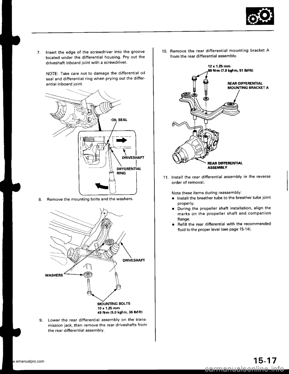
7. Insert the edge of the screwdriver into the groove
located under the differential housing Pry out the
driveshaft inboard ioint with a screwdraver.
NOTE: Take care not to damage the differential oil
seal and differential ring when prying out the differ-
ential inboard joint.
8. Remove the mounting bolts and the washers.
DRIVESHAFT
MOUNTING BOLTS'10 x 1 .25 mm,19 N'm (5 0 kgf m, 36 lbtftl
Lower the rear differential assembly on the trans-
mission jack, then remove the rear driveshafts from
the rea r difterential assembly.
DIFFERENTIAL
12 x 1.25 fifi
10. Remove the rear difterential mounting bracket A
from the rear differential assembly.
N.m {7.0 lgf.m. 5l lbl.tt)
REAR DIFFERENTIALMOUNTING BRACKET A
REAN DFFERENTI,ALASSEMBLY
11.Install the rear differential assembly in the reverse
order of removal.
Note these items during reassembly
. lnstall the breather tube to the breather tube joint
properly.
. During the propeller shaft installation, align the
marks on the propeller shaft and companion
flange.
. Reiill the rear differential with the recommended
fluid to the proper level {see page 15-14).
15-17
www.emanualpro.com
Page 815 of 1395
12. Install the special tools to the companion flange,
then tighten the locknut to specified torque.
TOROUE: 118 N.m (12.0 kgf-m,87 lbf'ft)
HOLDEB HANDLE07JAB - @1020A
Stake the locknut tab into the
guide.
I x I .25 mm32 N'm (3.3 kgt m, 24 lbtftl
groove in the clutch
14. lnstall the breather tube.
OIL FILI..ER PLUG47 N.m 14.8 kgf.m,35 tbt frl
WASHENSReplace.
DRAIN PLUG4? N'm l4.E tgf.m, 35 lbf'ftl
t5.Installthe drain plug and the oilfiller plug with
wasners.
BREATHER TUAE
www.emanualpro.com
Page 876 of 1395

Power Steering Gearbox
Removal
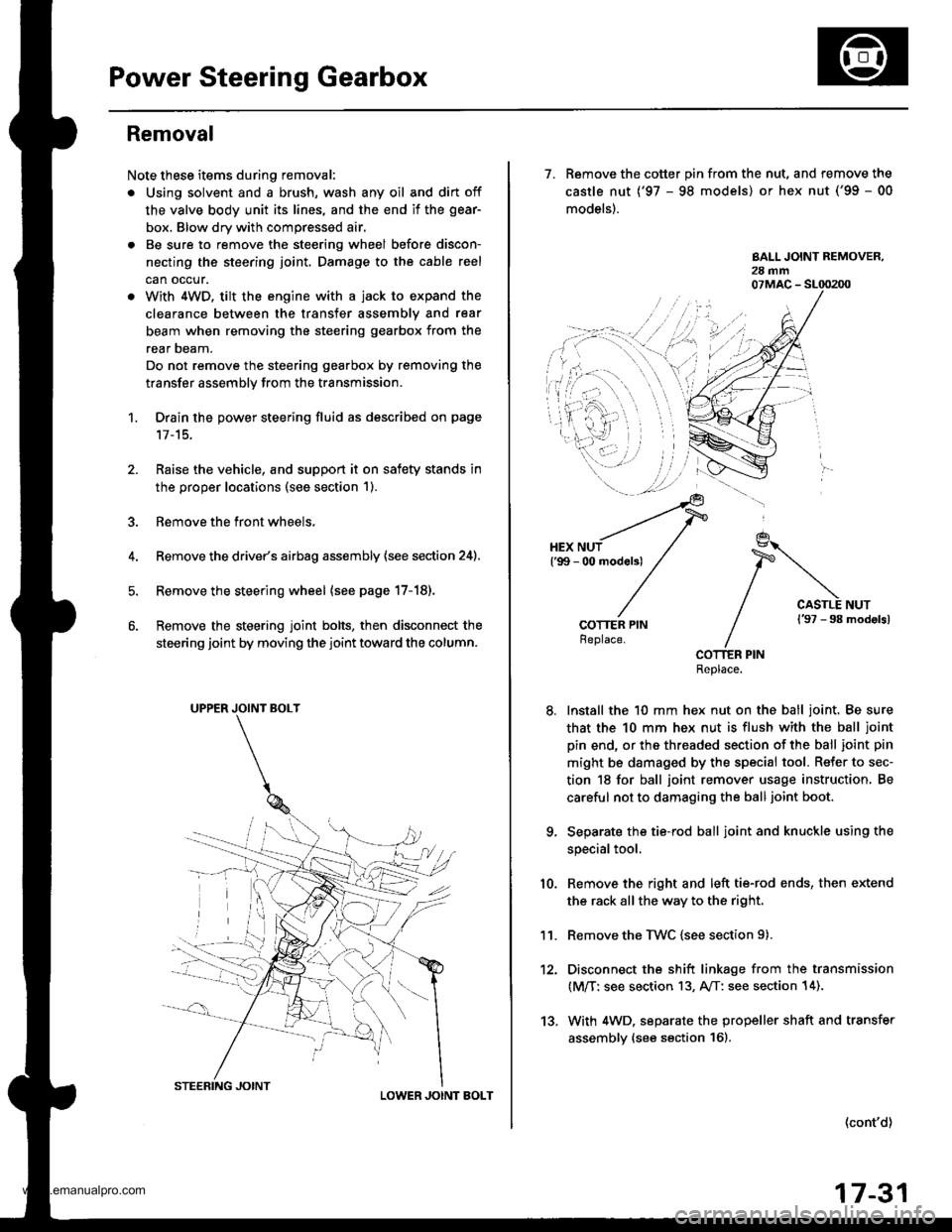
Note these items during removal:
. Using solvent and a brush, wash any oil and dirt off
the valve body unit its lines, and the end if the gear-
box. Blow dry with compressed air.
. Be sure to remove the steering wheel before discon-
necting the steering joint. Damage to the cable reel
can occur.
. With 4WD. tilt the engine with a jack to expand the
clearance between the transfer assembly and rear
beam when removing the steering gearbox from the
rear oeam.
Do not remove the steering gearbox by removing the
transfer assembly from the transmission.
1. Drain the power steering fluid as described on page'17-15.
Raise the vehicle, and suppon it on safety stands in
the proper locations (see section 1).
Remove the front wheels,
Remove the drive/s airbag assembly {see section 24).
Remove the steering wheel {see page 17-18).
Remove the steering joint bolts, then disconnect the
steering joint by moving the joint toward the column.
UPPER JOINT BOLT
LOWER JOINT BOLT
13.
7. Remove the cotter pin from the nut, and remove the
castle nut {'97 - 98 models) or hex nut ('99 - 00
models).
COTTER PINReplace.
Install the 10 mm hex nut on the ball joint. Be sure
that the 10 mm hex nut is flush with the ball joint
pin end, or the threaded section of the ball joint pin
might be damaged by the special tool. Refer to sec-
tion 18 for ball joint remover usage instruction, Be
careful not to damaging the ball joint boot.
Separate the tie-rod ball joint and knuckle using the
special tool.
Remove the right and left tie-rod ends, then extend
the rack all the way to the right.
Remove the TWC (see section 9).
Disconnect the shift linkage from the transmission
(M/T: see section 13, A/T: see section 14).
With 4WD. separate the propeller shaft and transfer
assembly (see section 161.
10.
11.
(cont'd)
17-31
www.emanualpro.com
Page 886 of 1395

Valve Body Unh Roa$embly
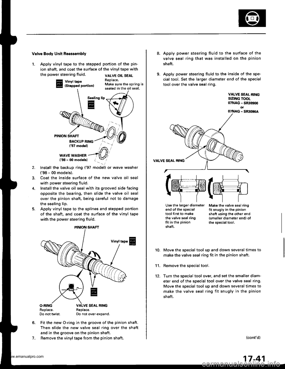
1. Apply vinyl tape to the stepped portion of the pin-
ion shaft, and coat the surface of the vinyl tape with
the power steering fluid.
Vinyl tape(Stopp6d portion)
VALVE OIL SEALReplace.Make sure the spring isseated in the oil seal.
Serling
E
7.
PINION SHAFT
BACKUP RING137 modell
WAVE WASHER{'98 - 00 modelsl
Install the backup ring {'97 model) or wave washer
('98 - 00 models).
Coat the inside surface of the new valve oil seal
with power steering fluid.
Install the valve oil seal with its grooved side facing
opposite the bearing, then slide the valve oil seal
over the pinion shaft, being careful not to damage
the sealing lip.
Apply vinyl tape to the splines and stepped ponion
of the shaft, and coat the surface of the vinyl tape
with the power steering fluid.
Vinyl trp€
O.RINGReplace.Do not twist.R€place-Do not over-expand.
Fit the new O-ring in the groove of the pinion shaft.
Then slide the new valve seal ring over the shaft
and in the groove on the pinion shaft,
Remove the vinyl tape from the pinion shaft.
\/
PINION SHAFT
8.Apply power steering fluid to the surface of the
valve seal ring that was installed on the pinion
shaft.
Apply power steering fluid to the inside of the spe-
cial tool. Set the larger diameter end of the special
tool over the valve seal ring.
VALVE SEAL RINGSIZNG TOOL07NAG - SR309q'ot07NAG - SR3oltoA
Mak€ the valve seal ringfit snugly in the pinion
shatt using th6 other end{smaller diameter end) otthe special tool.
10.
11.
12.
Move the special tool up and down several times to
make the valve seal ring fit in the pinion shaft,
Remove the soecial tool.
Turn the special tool over, and set the smaller diam-
eter end of the specisl tool over the valve seal ring.
Move the special tool up and down several times to
make the valve seal ring fit snugly in the pinion
shaft.
(cont'd)
lrr.rj1
tffifrE-rr.]
r\-''] 7
Usg th6 larg€r diameterend of the specialtoollirst to maketh€ valve seal ringtit in the pinion
shaft.
17-41
www.emanualpro.com