Page 168 of 1395
Crankshaft
12.
Installation (cont'd)
14.
13.
Apply liquid gasket to the oil pump mating surfaceof the block.
Apply a light coat of oil to the crankshaft, the lip ofthe seal, and the O-rings.
Apply grease to the lips of the oil seals.
Align the inner rotor with the crankshaft, then installthe oil pump. When the pump is in place, clean anyexcess grease off the crankshaft, then check that theoil seal lips are not distoned.
6x1,0mm9.8 N.m {1.0 kg{.m,,.2 tbf.ftl
I
{/^ I GASKET(..6 Replace."[z
O-RINGReplace.
OIL PUMP
6x1.0mm9,8 N.m 11.0 kg{.m,7.2lbt.trl
8 x 1.25 mm24 N.m {2.4 kgf.m,17 tbt.ftl
7 -22
,'t ./o,DowEL PtN
// |
16.Apply liquid gasket on
cover matrng areas.
CYLINDERBLOCK
the oil pump and right side
Apply liquid g€sketto these pornts.
17. Install the oil pan gasket and oil pan. Wait no
than five minutes after applying liquid gasket.
OIL PAN
OIL PANGASKETReplace.
Apply liquid gasketto these pornts,
www.emanualpro.com
Page 169 of 1395
Oil Seals
18. Tighten the bolts and nuts finger tight at six points.
Tighten all bolts and nuts, starting from nut O. clock-
wise in three steps. Excessive tightening can cause
distortion ot the oil pan gasket and oil leakage.
Torque: 12 N.m (1.2 kgt.m,8.7 lbtft)
19.
1.
lnstallation
Dry the crankshaft oil seal housing.
Apply a light coat of grease to the crankshsft and to
the lips of the seals.
Using the special tool, drive in the timing pulley-end
seal until the driver bottoms against the oil pump.
When the seal is in place, clean any excess grease
off the crankshaft and check that the oil seal lip is
not distorted,
SEAL DRIVEROTLAD - PT3O1OAlnstall sealwith theparts number sidefacing out.
(cont'd)
7-23
www.emanualpro.com
Page 173 of 1395
lllustrated Index
OIL CONTROLORIFICE
OIL PUMPOverhaul, page 8-8Removal/lnspection, page 8 IApply liquid gasket tomating surface of engine block.
'99 - 00 models:KNOCK SENSOR31 N.m {3.2 kgf.m.23 lbl.ft)
ENGINE OIL PRESSURE SWITCH18 N.m {1.8 kgtm, 13lbl.ft)1/8 in. BSPT (British StandardPipe Taper) 28 Threads/inch.Use proper liquid sealant.
O-RING
DOWEL PIN
6x1.0mm9.8 N.m (1.0 kgf.m,7.2 tbl.ft)
8 x 1.25 mm24 N.m 12.4 kgf.m,17 tbf.ft)
BAFFLE PLATE
kgtm,7.2 lbtftl
Replace.
6x1.0mm9.8 N.m 11.0 kgf m,7.2 tbf.ftl
OIL PANGASKETReplace.
OIL PANBeferto page 7 22when installing.
6x1.0mm12 N.m 11.2 kglm,8.7 lblftl
WASHEBReplace.
DRAIN BOLT4,1N.m {,1.5 kgf'm,33 lbf ft)Do not overtighten.
'-- /o-RrNG ,/ Reptace.
\^ ./
v,/
U
6x1.0mm9.8 N.rn {1.0
SCREEN
8-3
www.emanualpro.com
Page 174 of 1395

Engine Oil
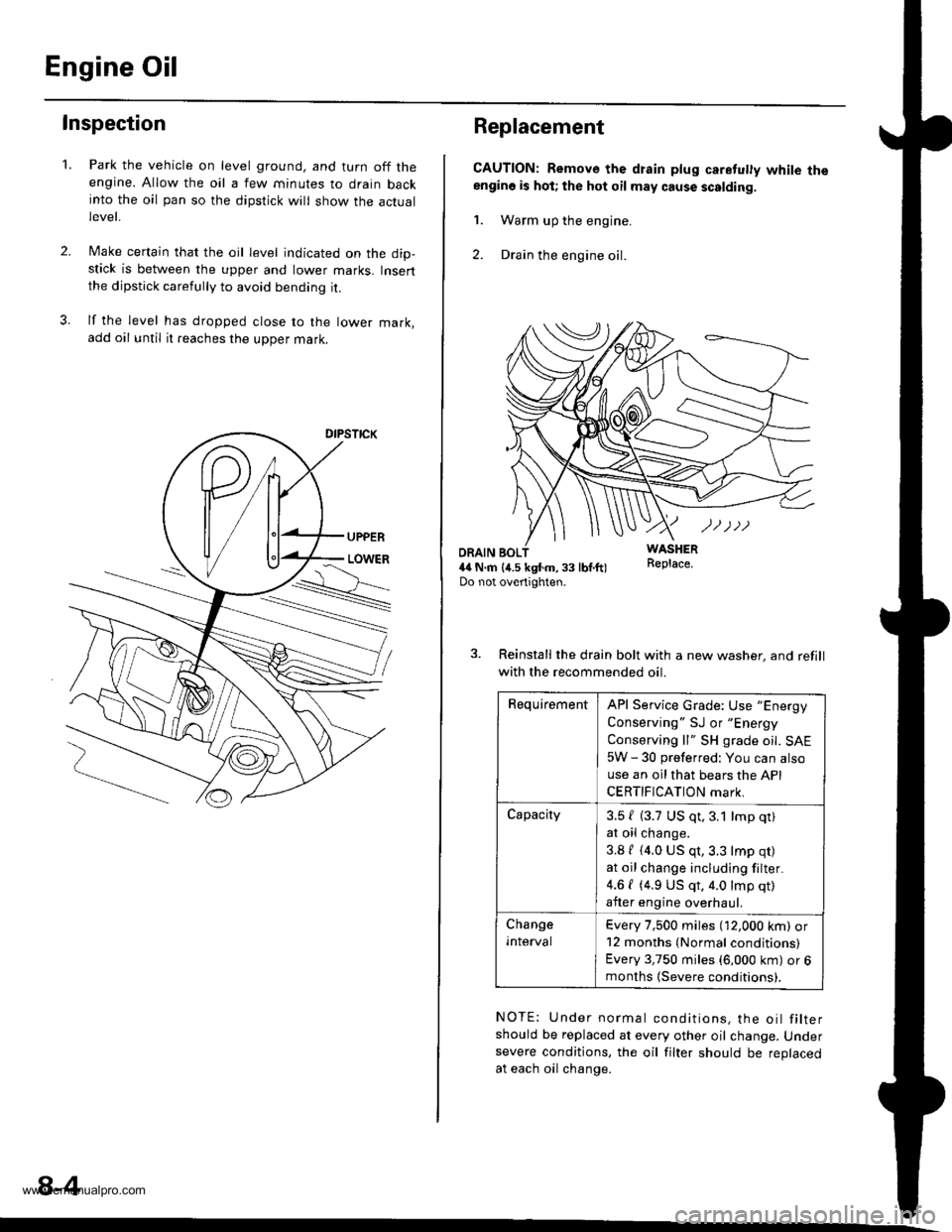
Inspection
2.
1.Park the vehicle on level ground, and turn off theengine. Allow the oil a few minutes to drain backinto the oil pan so the dipstick will show the actuallevet,
Make certain that the oil level indicated on the dip-stick is between the upper and lower marks. Insertthe dipstick carefully to avoid bending it.
lf the level has dropped close to the lower mark,add oil until it reaches the upper mark.
8-4
Replacement
CAUTION: Remove the drain plug caretuly white theengino is hot; the hot oil may cause scalding.
1. Warm up the engine.
2. Drain the engine oil.
WASHERR€place.ORAIN BOL4il N.m {4.5 kgtm,33 lbf.ft)Do not overtighten.
3. Reinstall the drain bolt with a new washer, and refill
with the recommended oil.
RequirementAPI Service Grade: Use "Energy
Conserving " SJ or "Energy
Conserving ll" SH grade oil. SAE
5W - 30 preferred: You can also
use an oil that bears the API
CERTIFICATION mark.
Capacity3.5 { (3.7 US qt,3.1 lmp qt)
at oil change.
3.8 / (4.0 US qt,3.3 lmp qr)
at oil change including filter.
4.6 { (4.9 US qt, 4.0 lmp qt)
after engine overhaul.
Change
Inlerval
Every 7,500 miles (12,000 km) or12 months (Normal conditions)
Every 3,750 miles (6,000 km) or 6months (Severe conditions).
NOTE: Under normal conditions, the oil filtershould be replaced at every other oil change. Undersevere conditions, the oil filter should be replacedat each oil change.
www.emanualpro.com
Page 179 of 1395

1.
2.
3.
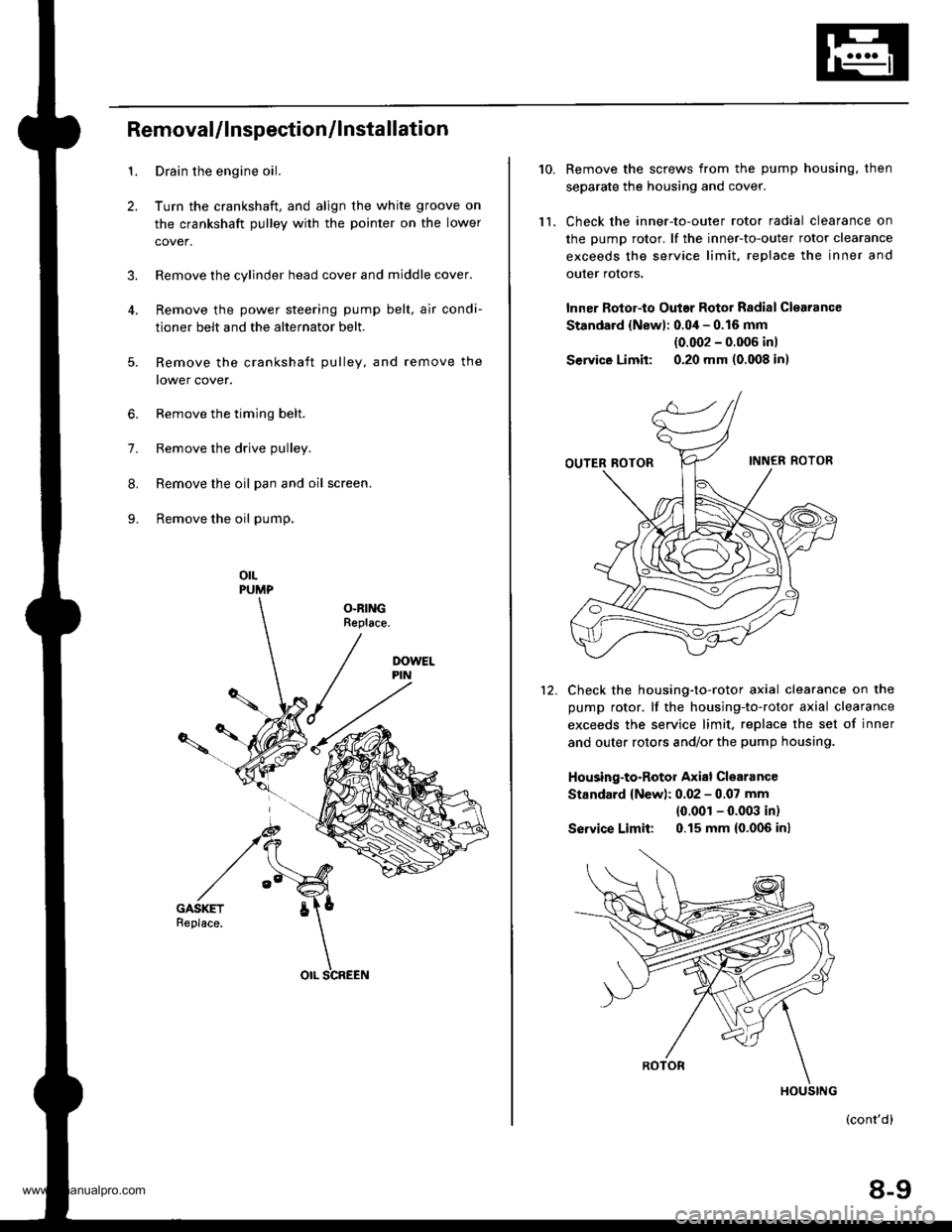
RemovaUlnspection/lnstallation
Drain the engine oil.
Turn the crankshaft, and align the white groove on
the crankshaft pulley with the pointer on the lower
cover.
Remove the cylinder head cover and middle cover.
Remove the power steering pump belt, air condi-
tioner belt and the alternator belt.
Remove the crankshaft pulley, and remove the
lower cover.
6. Remove the timing belt.
7. Remove the drive pulley.
8. Remove the oil pan and oil screen.
9. Remove the oil pump.
orLPUMP
OLRINGReplace.
5.
OIL SCREEN
10.
ll.
Remove the screws from the pump housing, then
separate the housing and cover.
Check the inner-to-outer rotor radial clearance on
the pump rotor. lf the inner-to-outer rotor clearance
exceeds the service limit. replace the inner and
outer rotors.
lnner Rotor-to Outar Rotor Radial Clearance
Standard {Newl: 0.04 - 0.16 mm
{0.002 - 0.006 inl
Service Limit: 0.20 mm (0.008 in)
Check the housing-to-rotor axial clearance on the
pump rotor. lf the housing-to-rotor axial clearance
exceeds the service limit. replace the set of inner
and outer rotors and/or the pump housing.
Housing-to-Rotor Axial Clearance
Standard {New): 0.02 - 0.07 mm
{0.001 - 0.003 in)
So|'�ice Limit: 0.15 mm (0.006 inl
(cont'd)
8-9
HOUSING
www.emanualpro.com
Page 180 of 1395

Oil Pump
13.
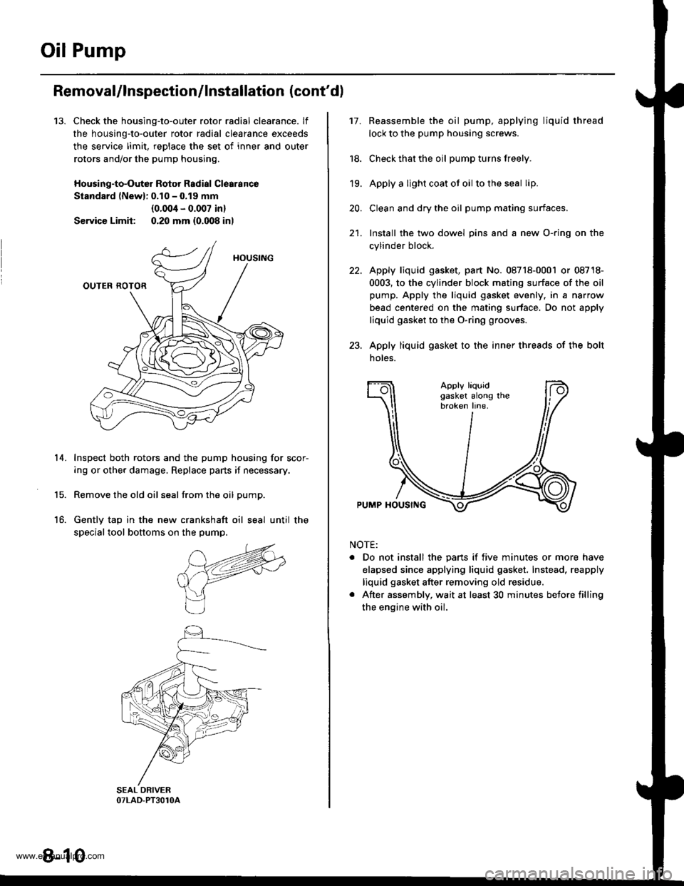
Removal/lnspection/lnstallation (cont'd)
Check the housing-to-outer rotor radial clearance. lf
the housing-to-outer rotor radial clearance exceeds
the service limit, reDlace the set of inner and outer
rotors and/or the pump housing,
Housing-to-Outer Rotor Radial Clearance
Standard lNewl: 0.10 - 0.19 mm
{0.004 - 0.007 in}
Service Limit: 0.20 mm {0.008 inl
Inspect both rotors and the pump housing for scor-
ing or other damage. Replace pans if necessary.
Remove the old oil seal from the oil pump.
Gently tap in the new crankshaft oil seal until the
special tool bottoms on the pump.
14.
15.
16.
8-10
17.Reassemble the oil pump, applying liquid thread
lock to the pump housing screws.
Check that the oil pump turns freely.
Apply a light coat ot oil to the seal lip.
Clean and dry the oil pump mating surfaces.
Install the two dowel pins and a new O-ring on the
cylinder block.
Apply liquid gasket, part No. 08718-0001 or 08718-
0003, to the cylinder block mating surface of the oil
pump. Apply the liquid gasket evenly, in a narrow
bead centered on the mating surface. Do not apply
liquid gasket to the O-ring grooves.
Apply liquid gasket to the inner threads of the bolt
noles.
18.
19.
20.
21.
Apply liquidgasket along thebroken line.
PUMP HOUSING
NOTE:
. Do not install the pans if five minutes or more have
elapsed since applying liquid gasket. Instead, reapply
liquid gasket after removing old residue.
. After assembly, wait at least 30 minutes betore filling
the engine with oil.
www.emanualpro.com
Page 181 of 1395
24.Apply grease to the lip of the oil pump seal.
Install the oil pump onto the crankshaft. When the
pump is in place, clean any excess grease off the
crankshaft and check that the oil seal lip is not dis-
torted.
lnstall the oil screen.
Install the oil pan {see page 7-22).2't .
8 x 1.25 mm24 N.m 12.4 kgf.m,'17 tbf.ft)
O-RINGApply engine oilReplace.
6x1.0mm9.8 N.m {1.0 kgf.m,1 .2lbfitl
DOWELPIN
6x1.0mm9.8 N.m (1.0 kgf.m.7.2 tbtftl
OIL PUMP
6x1.0mm9.8Nm(1.0kgf.m,7.2 tbt ft)
OIL SCBEEN
8-11
www.emanualpro.com
Page 386 of 1395

Fuel Supply System
Fuel Gauge
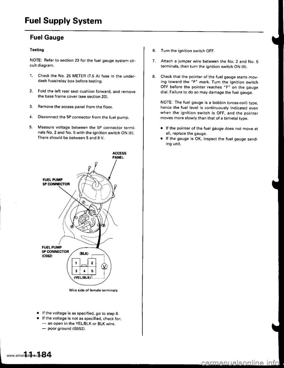
Tssting
NOTE: Refer to section 23 for the fuel gauge system cir-cuit diagram.
'1. Check the No. 25 METER (7.5 A) fuse in the under-dash fuse/relay box before testing.
2. Fold the left rear seat cushion forward, and remove
the base frame cover {see section 20).
3. Remove the access panel from the floor.
4. Disconnect the 5P connector from the fuel pump.
5. Measure voltage between the 5P connector termi-nals No.2 and No. 5 with the ignition switch ON ( ).There should be between 5 and 8 V.
FUEL PUMP5P CONNECTOR
tc56al
a
a
Wire side of female t€rminals
lf the voltage is as specified, go to step 6.lf the voltage is not as specified, check for:- an open in the YEUBLK or BLK wrre.- poor ground (c552).
11-184
7.
Turn the ignition switch OFF.
Attach a jumper wire between the No. 2 and No. 5terminals, then turn the ignition switch ON fll).
Check that the pointer of the fuel gauge starts mov-ing toward the "F" mark. Turn the ignition switchOFF before the pointer reaches "F" on the gauge
dial. Failure to do so may damage the luel gauge.
NOTE: The fuel gauge is a bobbin (cross-coil) type,hence the fuel level is continuously indicated evenwhen the ignition switch is OFF, and the pointer
moves more slowly than that of a bimetal type.
. lf the pointer of the fuel gauge does not move atall. replace the gauge.
. lf the gauge is OK, inspect the fuel gauge send-ing unit.
www.emanualpro.com