Page 1034 of 1395

Dashboard Removal and Installation
SRS components are located in this area. Review the SRS
component locations, precautions, and procedures in the
SRS section {24) before preforming repairs or service.
CAUTION:
. When prying with a flat-tip screwdriver, wrap h withprotective tap€, and apply protective tape around the
related parts to prevgnt damage.
. Put on gloves to prot€ct your hands.
NOTE:
. An assistant is helpful when removing and installing
the dashboard.
. Take care not to scratch the dashboard, bodv and
other related parts.
1.Make sure you have the anti-theft code for the
radio, then write down the frequencies for the
radio's preset buttons.
Disconnect the negative battery cable. and wait at
least three minutes before beginning work.
Removei
a Driver's dashboard lower cover and knee bolster(see page 20-48)
. Glove box (see page 20-49)
. Lower console cover and center pocket (A/T
model, see page 20-49)
. Center console and center upper pocket (M/T
model, see page 20-47)
. Center dashboard lower cover (see page 20-50)
. Power window switch (see page 20-51)
. Driver's side air vent (see page 20-52)
. Driver's side defogger trim (see page 20-52)
Disconnect the driver's airbag connector, and lower
the steering column (see section 17)
NOTE: To prevent damage to the steering column,
wrap it with a shop towel.
2.
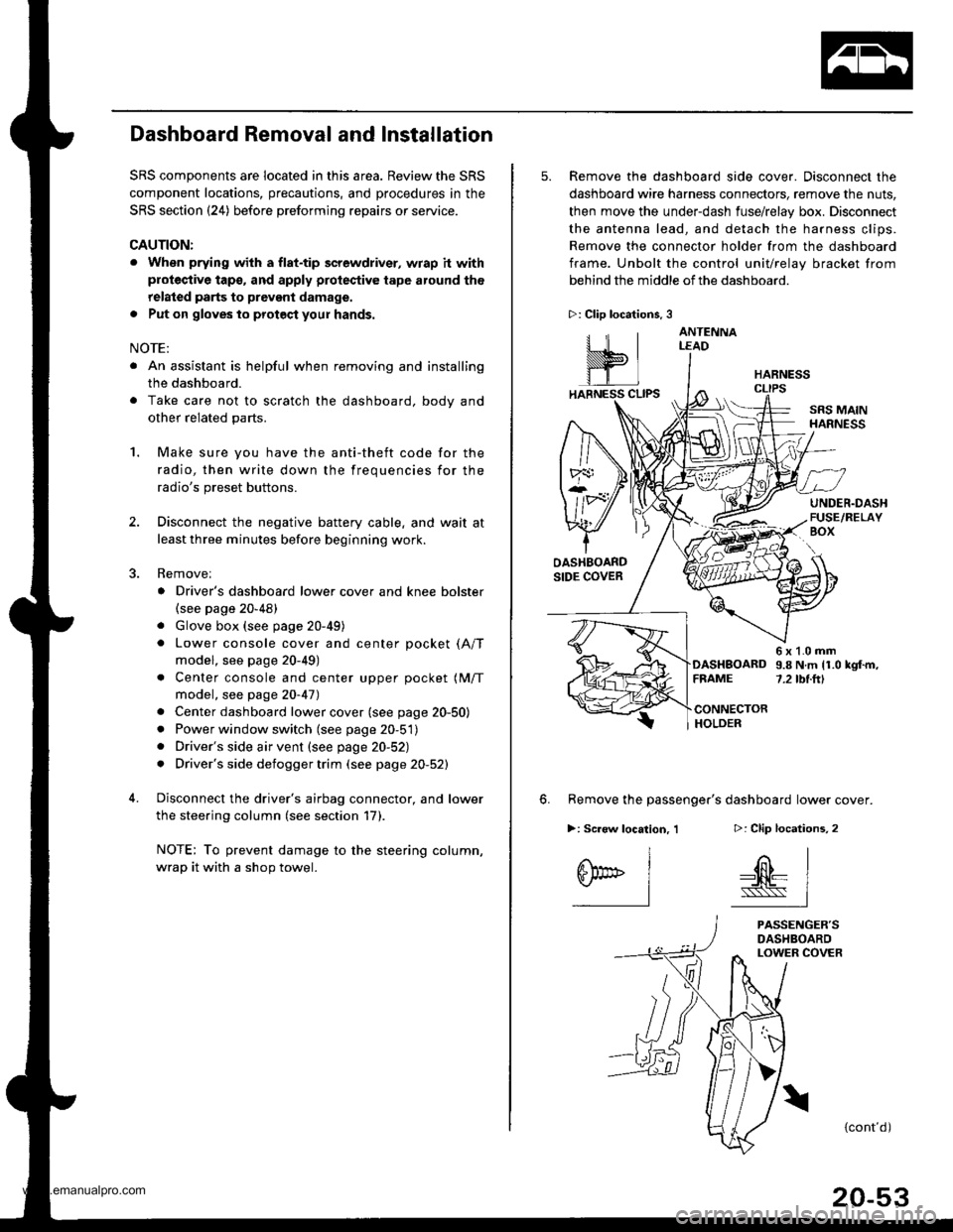
5. Remove the dashboard side cover. Disconnect the
dashboard wire harness connectors, remove the nuts,
then move the under-dash fuse/relay box. Disconnect
the antenna lead, and detach the harness clips.
Remove the connector holder from the dashboard
frame. Unbolt the control unit/relay bracket from
behind the middle of the dashboard.
HARNESS
6. Remove the passenger's dashboard lower cover.
D: Clip locations,
nl
-$t- Issj
I
ANTENNALEAD
>: Clip locations.
rttl
slllll
>: Scr€w location, 1
I
SF:oo I-l
SRS MAINHARNESS
UNDER.DASHFUSE/RELAYBOX
OASHBOARDSIDE COVER
6x1.0mm9.8Nm11.0kgf.m,7.2tbt.ftlDASHBOARDFFAME
CONNECTORHOLDER
PASSENGER'SDASHBOARDLOWER COVER
{cont'd)
www.emanualpro.com
Page 1038 of 1395
Front Seat Removal and Installation
CAUTION: When prying whh a tlat-tip screwdrivor, wrap
it with proteqtive tape to prevent damage.
NOTE: Take care not to scratch the bodv or tear the seat
covers.
1. Remove the seat track end cover, and remove the
bolts.
>: Bolt loc.tionsA>.3B>, 1
I x 1.25 mm22 N.mi'2.2 kgl.m,16 rbf.ftl
10 x 1.25 mm37 N.m13.8 kgt.m,27 tbt.ftl
2. Lift up the driver's front seat, then disconnect the
seat belt switch connector and harness clips.
>: Hrrnoss clip loc.lions
SEAT BELT SW]TCHCONNECTOR
Carefully remove the front seat through the door
opening.
NOTE: An assistant is helpful when removing the
front seat.
Installation is the reverse of the removal procedure.
NOTE: Make sure the seat belt switch connector is
connected properly (driver's front seat).
20-57
www.emanualpro.com
Page 1090 of 1395

a
Heater and Air Conditioning
Heater ...........21
NOTE: Section 21 ("Heater") is included in section 22.
Air Conditioning ......'..'.. '.'22'1
SUPPLEMENTAL RESTRAINT SYSTEM (SRS}
This model has an SRS which includes a driver's airbag in the steering wheel hub, a passenger's airbag in the dashboard
above the glove box ('97,00 models). and seat belt tensioners in the seat belt retractors ('98 - 00 models). Information
necessary to safely service the SRS is included in this Service Manual. ltems marked with an asterisk (*) on the contents
page include. or are located near, SRS components. Servicing, disassembling or replacing these items will require special
precautions and tools, and should only be done by an authorized Honda dealer.
@. To avoid rendering the SRS inoperative, which could lead to personal iniury or death in the event of 8 severe frontal
collision, all SRS service work must be performed by an authotized Honda dealer.
lmproper service procedures, including incorrect removal and installation of the SRS, could lead to personal iniury
caused by unintentional deployment of the airbags ('97 - 00 models), and seat belt tensioners 138 - 00 models).
Do not bump the SRS unit. Otherwise, the system may fail in case of a collision, or the airbags may deploy when the
ignition switch is ON {lll.
SRS eleqtrical wiring harnesses are identified by yellow color coding. Related components are located in the steering
column, front console, dashboard, dashboard lower panel, and in the dashboard above the glove box. Do not use elec-
tricaltest equipment on thes€ cilcuils.
www.emanualpro.com
Page 1093 of 1395
Component Location
lndex
EVAPORATORReplacement, page 22-48Overhaul, page 22-49
SERVICE VALVEILOW-PRESSURE SIDE}
CONDENSERReplacement, page 22-70
A/C PRESSURE SWTTCHWhen the refrigorant pressure is below 200 kPa 12.0 kglc.r|r,28 psi) or abov€ 3,200 kPa (32 kgflcmr, 455 psi), the AJC pressureswitch opens the circuit to the Ay'C switch and stops the airconditioning to protect the compressor.
Replacement, page 22-62Clutch Inspection, page 22-65Clutch Overhaul, pago 22-66Thermal Protector Replacement, page 22-68Relief Valve Replacem€nt. page 22-68
SERVICE VALVEIHIGH-PRESSURE SIDEI
,
[\,
-il
(cont'd)
www.emanualpro.com
Page 1094 of 1395
Component Location
lndex (cont'dl
SRS components are located in this area. Review the SRS component locations, precautions, and procedures in the SRS
section (24) before performing repairs or service.
BLOWER UNITReplacement, page 22-46Ovethaul, page 22 47
/alowen ruoronl
\Test, page 22-16 /
EVAPORATORFeplacement, page 22-48Overhaul, page 22,49
RECIRCULATIONCONTROL MOTORReplacement, page 22 42
HEATER UNITReplacement, page 22 50Overhaul, page 22 52
lest, pag.e 22 42
A/C FILIERReplacement. page 22-50VALVE CABLEAdjustment, page 22-53
RECIRCULATIONCONTROL SWITCH
a/c swtTcH
MODEMOTOR
REAR WINDOWDEFOGGERSwlTCHSee section 23Replacement, page 22-41Test, page 22-41MODE CONTROLDIAL
HEATER CONTROLPANELReplacement, page 22 46
swtTcH
22-4
CONTROL
www.emanualpro.com
Page 1095 of 1395
SLOWER MOTOR RELAY,RADIATOR FAN RELAY.CONDENSER FAN REI-AY,COMPRESSOR CLUTCH RELAY(Located in the undeFhood fuse/relay box)Test. page 22-45
CONDENSER FAN 2P CONNECTOB
RADIATOR FAN2P CONNECTORA/C PRESSURE SWITCH2P CONNECTOR
COMPARTMENTWIRE HARNESS
{cont'd)
1P CONNECTOR
22-5
www.emanualpro.com
Page 1104 of 1395

Troubleshooting
Blower Motor Speed
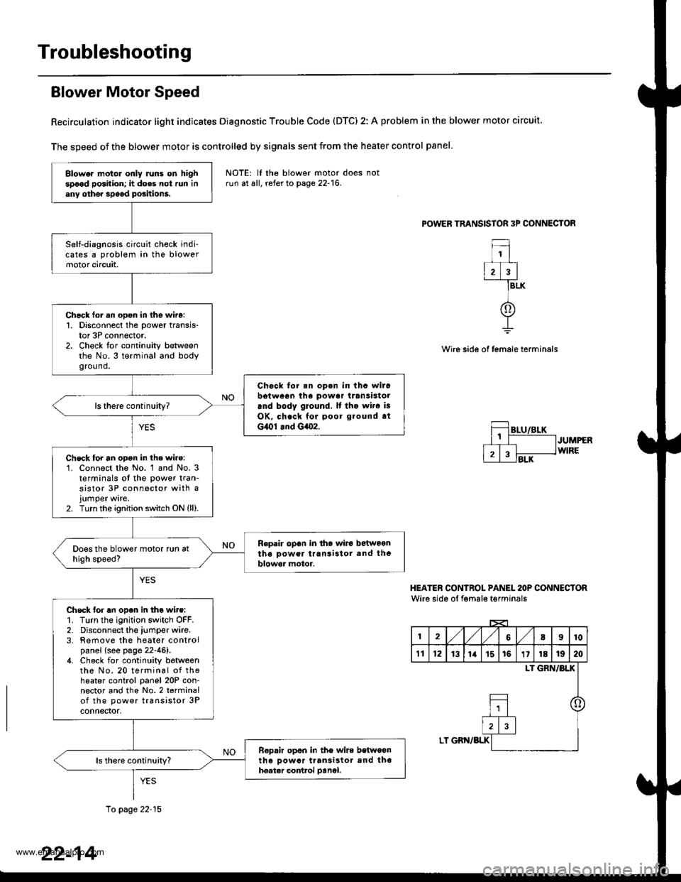
Recirculation indicator light indicates Diagnostic Trouble Code (DTC) 2: A problem in the blower motor circuit
The speed of the blower motor is controlled by signals sent from the heater control panel
POWER TRANSISTOR 3P CONNECTOR
1
2)3
f
BLK
Wire side of female terminals
JUMPERWIRE
HEATER CONIROL PANEL 2OP CONNECTORWire side oI fgmale t€rminals
12,/1,/68I10
't112131ia't51611181920
LI GRN/BLK
o
LT GBN/BLK
Blower motol only runs on highspood position; h does not run inany othe. speod positions.
Self-diagnosis circuit check indi-cates a problem in the blowermotor circuit,
Chack lor.n open in the wire:1. Disconnect the power transis-tor 3P connector.2. Check for continuity betweenthe No.3 terminal and bodygro(1nd.
Chock for.n op.n in thc wirobotween ihe powa. transistorrnd body ground, It tho wir. is
OK, check for poor ground atG,O1 .nd G4o2.
ls there continuity?
Chsck for an opon in the wire:'1. Connect the No. 1 and No. 3t€rminals of the power tran-sistor 3P connector with ajumper ware.2. Turn the ignition switch ON {ll).
Repair op6n in the wiro betwoontho Dower transi3tol and theblowor motor.
Check tor an open in tho wire:1. Turn the ignition switch OFF.2. Disconnect the iumper wire.3. Remove the heater controlpanel (see page 22-46).4. Check for continuity botweenthe No. 20 terminal of theheater control panel 20P con-nector and the No.2 terminalof the power transistor 3Pconnectof,
R€pair opon in tho wire betwoenth6 oowor ttan3i3tor and th6hoatar control oanel.
NOTE: lf the blower motor doesrun at all, refer to page 22-16.
10 page 22-15
22-14
www.emanualpro.com
Page 1105 of 1395

From page 22-14
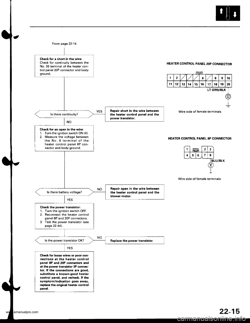
Chock for a short in the wire:Check tor continuity between theNo. 20 terminal of the heater con'trol panel 20P connector and bodyground,
R.p.ir short in the wire betwoenth. herter control Denel snd theoowor tranSastor.
Check to. an open in the wire:1. Turn the ignition swilch ON (ll).
2. Measure the voltage betweenthe No. I terminal of theheater control panel 8P con-nector and body ground.
Repair opan in the wire betwaentho heatsr cont.ol o.nel and theblower motor.ls there battery voltage?
Chock th6 power iransistor:1. Turn the ignition switch OFF.2. Reconnect the heater controlpanel 8P and 20P connectors.3. Test the power transistor (seepage 22 44).
ls the power transistor OK?
Chec* for loo3e wires or Door oon-neclions at the heater controlpanel 8P and 20P connoctors andat lhe power tran3istor 3P connec-tor. lf lhe connectiorc are good,substituta , known-good hoatercontrcl pan6l, and r€check. ll thesymptom/indication goes away.replecg th6 original heater controloanel.
HEATER CONTROL PANEL 2OP CONNECTOR
2,/1,/l/68910
1112131a151617181920
LT GRN/BLK
o
Wire side of female terminals
HEATER CONTROL PANEL 8P CONNECTOR
BLU/8LK
Wire side of female terminals
1
4678
22-15
www.emanualpro.com