1999 HONDA CR-V steering rack
[x] Cancel search: steering rackPage 859 of 1395
Inspection and Adjustment
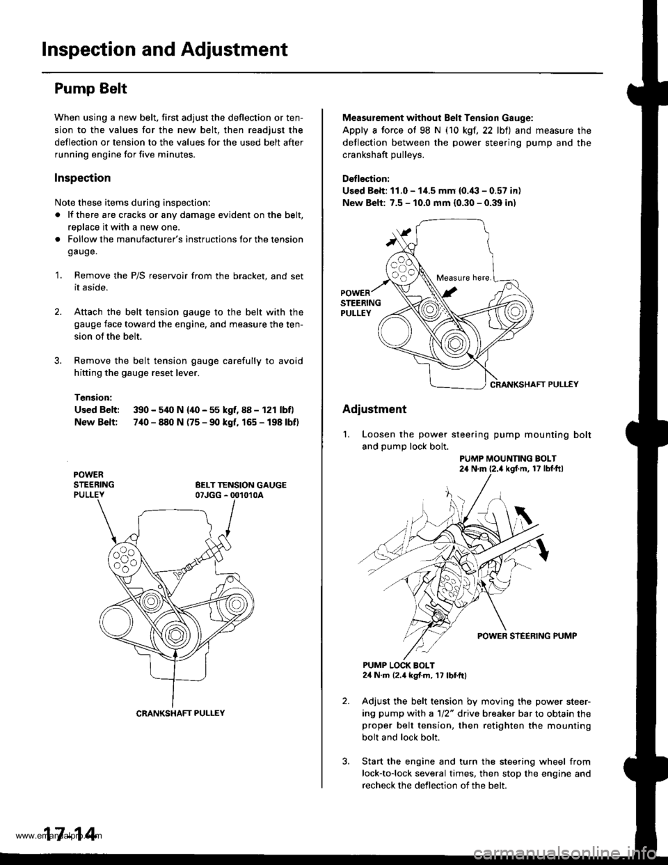
Pump Belt
When using a new belt. first adjust the deflection or ten-
sion to the values for the new belt, then readjust the
deflection or tension to the values for the used belt after
running engine for five minutes.
Inspection
Note these items during inspection:
a lf there are cracks or any damage evident on the belt,
replace it with a new one.
. Follow the manufacturer's instructions lor the tension
gauge.
'1. Remove the P/S reservoir from the bracket, and set
it aside.
2. Attach the belt tension gauge to the belt with the
gauge face toward the engine, and measure the ten-
sion of the belt.
Remove the belt tension gauge carefully to avoid
hitting the gauge reset lever.
Tension:
Used Belt: 390 - 540 N {40 - 55 kgf, 88 - 121 lbf)
New Belt: 7,[0 - 840 N (75 - 90 kgf, 165 - 198 lbf)
CRANKSHAFT PULLEY
17-14
Measurement without Belt Tension Gauge:
Apply a force ot 98 N (10 kgf,22 lbt) and measure the
deflection between the power steering pump and the
crankshaft oullevs.
Deflection:
Used Belt: 11.0 - 1i1.5 mm {0.'(l - 0.57 in)
New Belt: 7.5 - 10.0 mm {0.30 - 0.39 in)
CRANKSHAFT PULLEY
Adiustment
'1. Loosen the power steering pump mounting bolt
and pump lock bolt.
PUMP MOUNNNG BOLT24 N'm (2.4 kgf'm, 17 lbf ftl
PUMP LOCK BOLT24 N.m 12.4 kgf.m, 17 lbf.ftl
Adjust the belt tension by moving the power steer-
ing pump with a 1/2" drive breaker bar to obtain theproper belt tension, then retighten the mounting
bolt and lock bolt.
Start the engine and turn the steering wheel from
lock-to-lock several times, then stop the engine and
recheck the deflection of the belt.
Measure here.
www.emanualpro.com
Page 860 of 1395
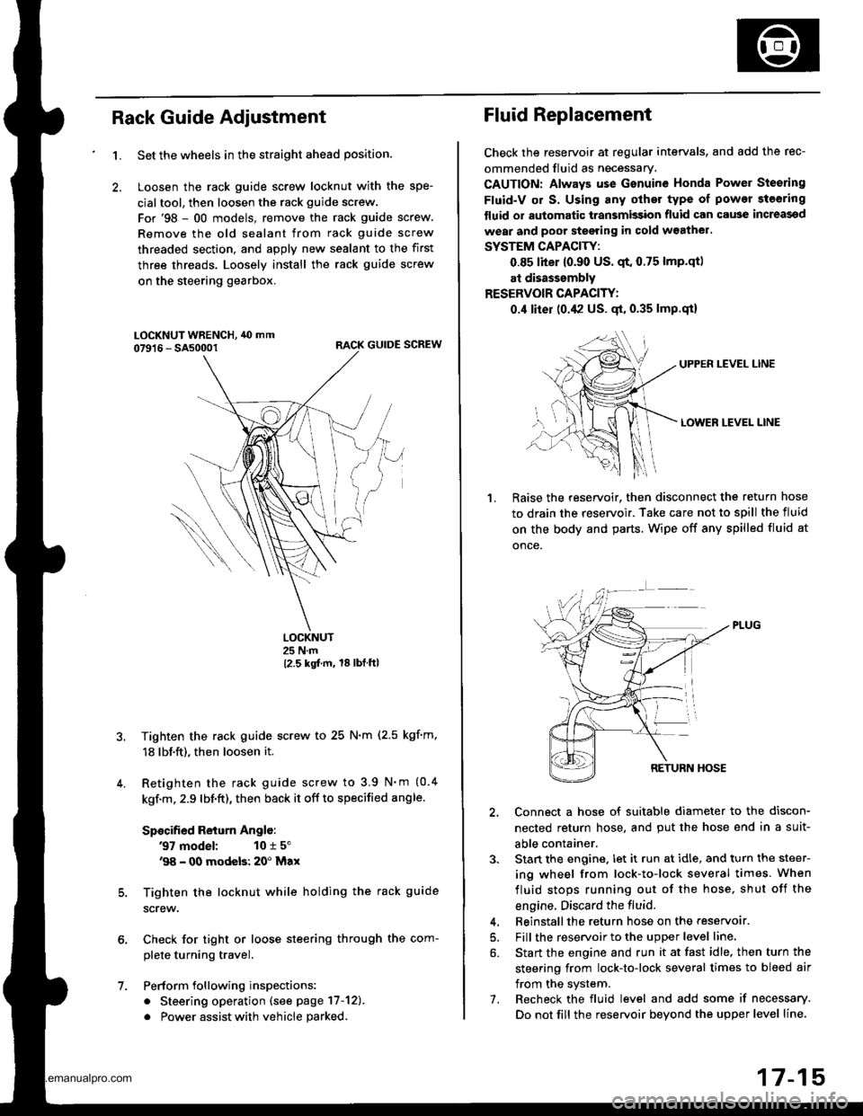
Rack Guide Adjustment
1.
6.
7.
5.
4.
Set the wheels in the straight ahead position.
Loosen the rack guide screw locknut with the spe-
cialtool, then loosen the rack guide screw.
For'98 - 00 models, remove the rack guide screw.
Remove the old sealant from rack guide screw
threaded section, and apply new sealant to the first
three threads. Loosely install the rack guide screw
on the steering gearbox.
RACK GUIDE SCREW
LOCKNUT25 N.m
12.5 kgt m, 18lbtftl
Tighten the rack guide screw to 25 N.m (2.5 kgf'm,
18 lbf.ft), then loosen it.
Retighten the rack guide screw to 3.9 N'm (0.4
kgf.m, 2.9 lbf.ft), then back it off to specified angle.
Specified Return Anglo:
37 model: 10 r 5"'98 - 00 modeb: 20' Max
Tighten the locknut while holding the rack guide
screw.
Check for tight or loose steering through the com-
plete turning travel.
Perform following inspections:
. Steering operation (see page 17-12).
. Power assist with vehicle parked
Fluid Replacement
Check the reseryoir at regular intervals, and add the rec-
ommended fluid as necessary.
CAUTION: Always use Gsnuine Honda Power Steering
Fluid-V or S. Using any other type of power steering
tluid or automatic transmission fluid can cause increassd
wear and poor steering in cold w3athel.
SYSTEM CAPACITY:
0.85 liter {0.90 US. qt. 0.75 lmp.qtl
at disasssmbly
RESERVOIR CAPACITY:
0.,1 liter (0.42 US. gt, 0.35 lmp.qi)
UPPEN LEVEL LINE
LOWER LEVEL LINE
1.Raise the reservoir. then disconnect the return hose
to drain the reservoir. Take care not to spill the fluid
on the body and parts. Wipe off any spilled fluid at
once.
2, Connect a hose of suitable diameter to the discon-
nected return hose, and put the hose end in a suit-
able container.
3. Stan the engine. let it run at idle, and turn the steer-
ing wheel from lock-to-lock several times. When
fluid stops running out of the hose, shut off the
engine. Discard the fluid.
4. Beinstallthe return hose on the reservoar.
5. Fill the reservoir to the upper level line,
6. Start the engine and run it at fast idle. then turn the
steering from lock-to-lock several times to bleed air
from the system.
7. Recheck the fluid level and add some if necessary.
Do not fill the reservoir beyond the upper level line.
www.emanualpro.com
Page 866 of 1395

8. Installation is the reverse ofthe removal procedure.
Note these items during installation:
. Be sure the wires are not caught or pinched by
any parts when installing the column.
a Make sure the wire harness is routed and fas-
tened properly.
. Make sure the connectors are properly connected.
. Make sure the steering joint is connected as fol-
lows:
a. lnsert the uDper end of the steering joint onto
the steering shaft (line up the bolt hole with
the flat ot the shaft).
b. Slip the lower end of the steering ioint onto
the Dinion shaft (lins up the bolt hole with the
groove around the shaft). and installthe lower
ioint bolt. Be sure that the lower joint bolt is
securely in the groove in the pinion shaft'
c. Pull on the steering joint to make sure that the
steering joint is JullY seated.
Then install the upper joint bolt and tighten it.
22 N.m (2.2 kgf.m, 16lbt.ftl
UPPER JOINT BOLT
Bolt must Iine uPwith fl6t on shaft.
Flat ponion.
SIEERING JOIMT
STECRING JOINT
LOWER JOINT BOLTBolt must line up withgroove around on shaft,
Inspection
Check the steering column ball bearing and the steer-
ing joint bearings for play and proper movement. lf
there is noisy or if there is excessive play, replace the
steering column as an assemblY
Check the retaining collar for damage. lf it is dam-
aged, replace the retaining collar.
PLASl'tCINJECTIONS
ABSOBBINGPLATE
SHIFT I.EVER
. Check the absorbing plates, absorbing plate guides
and sliding capsules Jor distortion and breakage.
ReDlace the column as an assembly if they are dis-
torted or broken.
SLIDING CAPSUIIThis part is attachedto the column bracketwith the plastic injections.
FETAINING COLLAR
ABSORBINGPLATE GUIDE
|GNMON SWTTCHSee section 23.(cont'd)
17-21
See section 14.
www.emanualpro.com
Page 869 of 1395

Power Steering Pump
Replacement
1.Place a suitable container under the vehicle.
Drain the power steering fluid from the reservoir.
Remove the belt by loosening the pump mountingbolt and pump lock bolt.
PUMP MOUNNNG BOI.T24 N.m 12.4 kgt m, 17 lbl.ftl
PUMP LOCK BOLT24 N.m (2.4 kg{.m, 1, tbfttl
Cover the IVC compressor with several shop towelsto protect it from spilled power steering fluid.Disconnect the pump inlet hose and pump outlethose from the pump, and plug them. Take care notto spill the lluid on the body or parts. Wipe off anyspilled fluid at once.
Remove the pump mounting bolt and pump lockbolt, then remove the pump. Do not turn the steer-ing wheelwith the pump removed.
Cover the opening of the pump with a piece of tapeto prevent foreign materialfrom entering the pump.
PUMP OU'I.TT HOSE
11 N.m (1.1 kgf.m,E rbf.ti)
17-24
7.Connect the pump inlet hose and pump outlet hose.Tighten the pump fittings securely.
Loosely install the pump in the pump bracket withthe mounting bolt and lock bolt.
Install the pump belt.
Note these items du.ing belt instsllation:. Make sure that the power steering belt is proper-
ly positioned on the pulleys.
. Do not get power steering fluid or grease on thepower steering belt or pulley faces, Clean off anyfluid or grease before installation
FOWER STEER G EELT
PUTrlY
Adiust the pump belt (see page 17-141.
Fill the reservoir to the upper level line (see page't7 -151..
10.
'l l.
www.emanualpro.com
Page 876 of 1395
Power Steering Gearbox
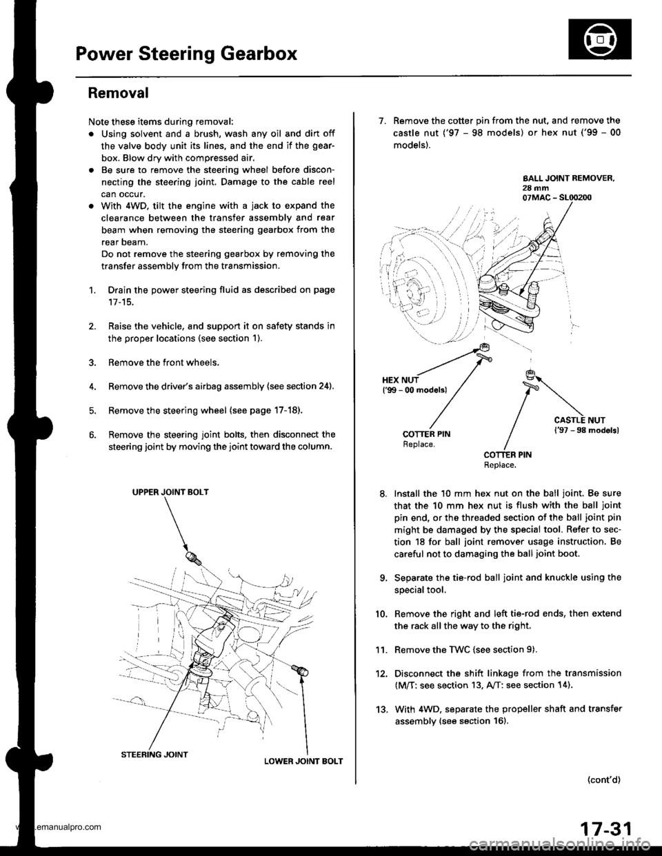
Removal
Note these items during removal:
. Using solvent and a brush, wash any oil and dirt off
the valve body unit its lines, and the end if the gear-
box. Blow dry with compressed air.
. Be sure to remove the steering wheel before discon-
necting the steering joint. Damage to the cable reel
can occur.
. With 4WD. tilt the engine with a jack to expand the
clearance between the transfer assembly and rear
beam when removing the steering gearbox from the
rear oeam.
Do not remove the steering gearbox by removing the
transfer assembly from the transmission.
1. Drain the power steering fluid as described on page'17-15.
Raise the vehicle, and suppon it on safety stands in
the proper locations (see section 1).
Remove the front wheels,
Remove the drive/s airbag assembly {see section 24).
Remove the steering wheel {see page 17-18).
Remove the steering joint bolts, then disconnect the
steering joint by moving the joint toward the column.
UPPER JOINT BOLT
LOWER JOINT BOLT
13.
7. Remove the cotter pin from the nut, and remove the
castle nut {'97 - 98 models) or hex nut ('99 - 00
models).
COTTER PINReplace.
Install the 10 mm hex nut on the ball joint. Be sure
that the 10 mm hex nut is flush with the ball joint
pin end, or the threaded section of the ball joint pin
might be damaged by the special tool. Refer to sec-
tion 18 for ball joint remover usage instruction, Be
careful not to damaging the ball joint boot.
Separate the tie-rod ball joint and knuckle using the
special tool.
Remove the right and left tie-rod ends, then extend
the rack all the way to the right.
Remove the TWC (see section 9).
Disconnect the shift linkage from the transmission
(M/T: see section 13, A/T: see section 14).
With 4WD. separate the propeller shaft and transfer
assembly (see section 161.
10.
11.
(cont'd)
17-31
www.emanualpro.com
Page 879 of 1395
Power Steering Gearbox
Removal (cont'dl
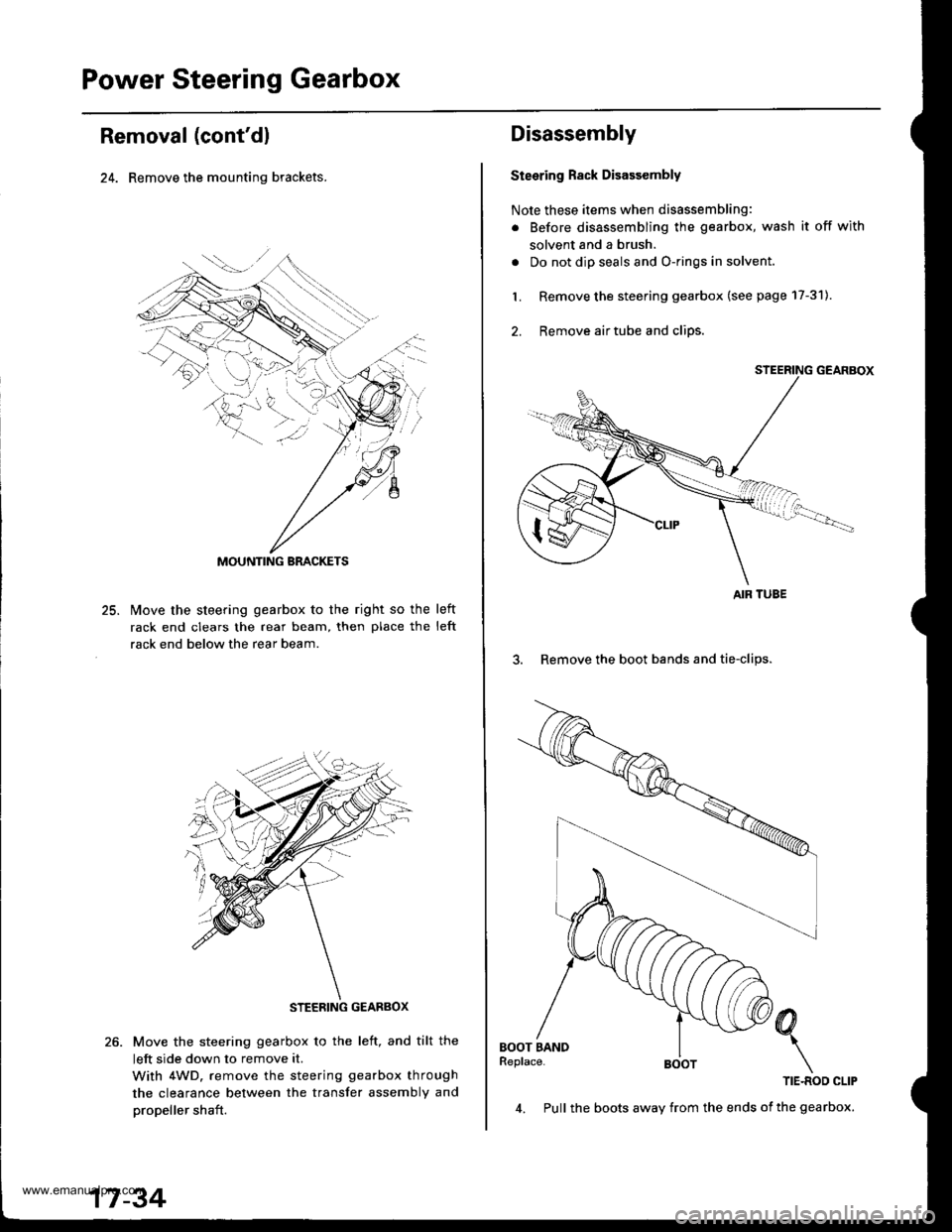
24. Remove the mounting brackets.
25.lvlove the steering gearbox to the right so the
rack end clears the rear beam, then place the
rack end below the rear beam.
left
left
Move the steering gearbox to the left, and tilt the
left side down to remove it.
With 4WD. remove the steering gearbox through
the clearance between the transfer assembly and
propeller shaft.
MOUNTING BRACKETS
STEEBING GEARBOX
17 -34
4. Pull the boots away from the ends of the gearbox.
Disassembly
Steering Rack Disassembly
Note these items when disassembling:
. Before disassembling the gearbox, wash it off with
solvent and a brush.
. Do not dip seals and O-rings in solvent.
1. Remove the steering gearbox (see page 17-31).
2. Remove airtube and clips.
3. Remove the boot bands and tie-clips.
AIR TUBE
www.emanualpro.com
Page 880 of 1395
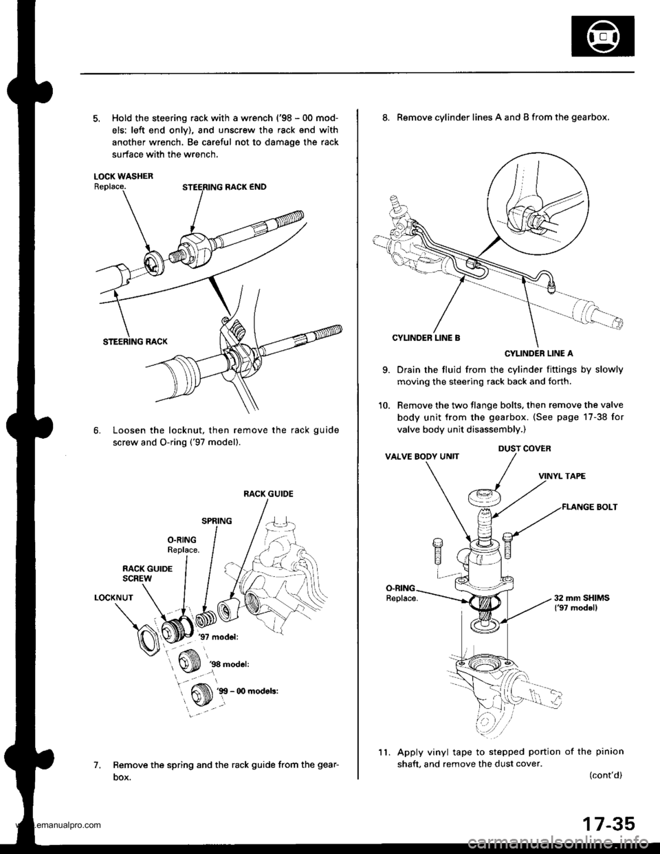
5. Hold the steering rack with a wrench {'98 - 00 mod-
els: left end onlv), and unscrew the rack end with
another wrench, Be careful not to damage the rack
surface with the wrench,
LOCK WASHER
Loosen the locknut, then remove the rack guide
screw and O-ring ('97 model).
6.
1.
LOCKNUT
Remove the spring and the rack guide from the gear-
DOX.
RACK GUIDE
9.
8. Remove cylinder lines A and B from the gearbox,
CYLINDER LINE A
Drain the fluid from the cylinder fittings by slowly
moving the steering rack back and {orth.
Remove the two tlange bolts, then remove the valve
body unit from the gearbox. (See page 17-38 for
valve body unit disassembly.)
VINYL TAPE
FLANGE BOLT
Apply vinyl tape to stepped portion of the pinion
shaft, and remove the dust cover.(cont'd)
DUST COVER
11.
17-35
www.emanualpro.com
Page 881 of 1395
Power Steering Gearbox
Disassembly {cont'd}
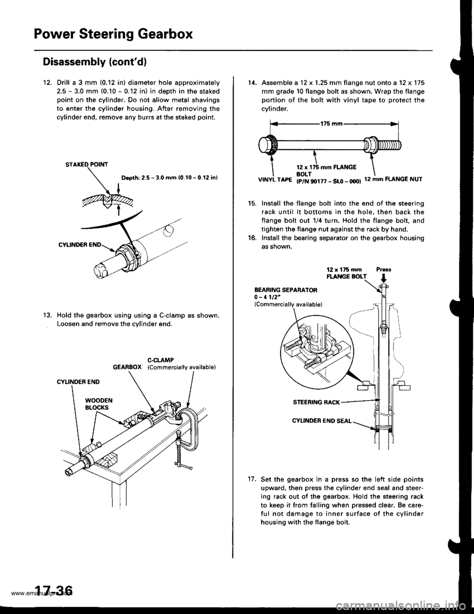
12. Drill a 3 mm (0.12 in) diameter hole approximately
2.5 - 3.0 mm (0.10 - 0.12 in) in depth in the staked
point on the cylinder. Do not allow metal shavings
to enter the cylinder housing. After removing the
cylinder end, remove any burrs at the staked point.
D.oth: 2.5 - 3.0 mm 10.10 - 0.12 inl
CYUNOER
Hold the gearbox using using a C-clamp as shown,
Loosen and remove the cvlinder end.
13.
17-36
14, Assemble a 12 x 1.25 mm flange nut onto a '12 x 175
mm grade 10 flange bolt as shown, Wrap the flange
portion of the bolt with vinyl tape to protect the
cvlinder,
VINYL TAP€ tp/N 90177 - SLO - OOOI 12mmFLANGENUT
Install the flange bolt into the end of the steering
rack until it bottoms in the hole. then back the
flange bolt out 1/4 turn. Hold the flange bolt, and
tighten the flange nut against the rack by hand.
Install the bearing separator on the gearbox housing
as snown.
15.
BEARING SEPARATOR0 - 1112'(Commercially available)
17.
STEERING RACK
CYLINDER €ND
Set the gearbox in a press so the lelt side points
upward, then press the cylinder end seal and steer-
ing rack out of the gearbox. Hold the steering rack
to keep it from falling when pressed clear. Be care-
ful not damage to inner surface of the cylinder
housing with the flange bolt.
www.emanualpro.com