1999 HONDA CR-V ball joint
[x] Cancel search: ball jointPage 895 of 1395
Power Steering Gearbox
Reassembly (cont'd)
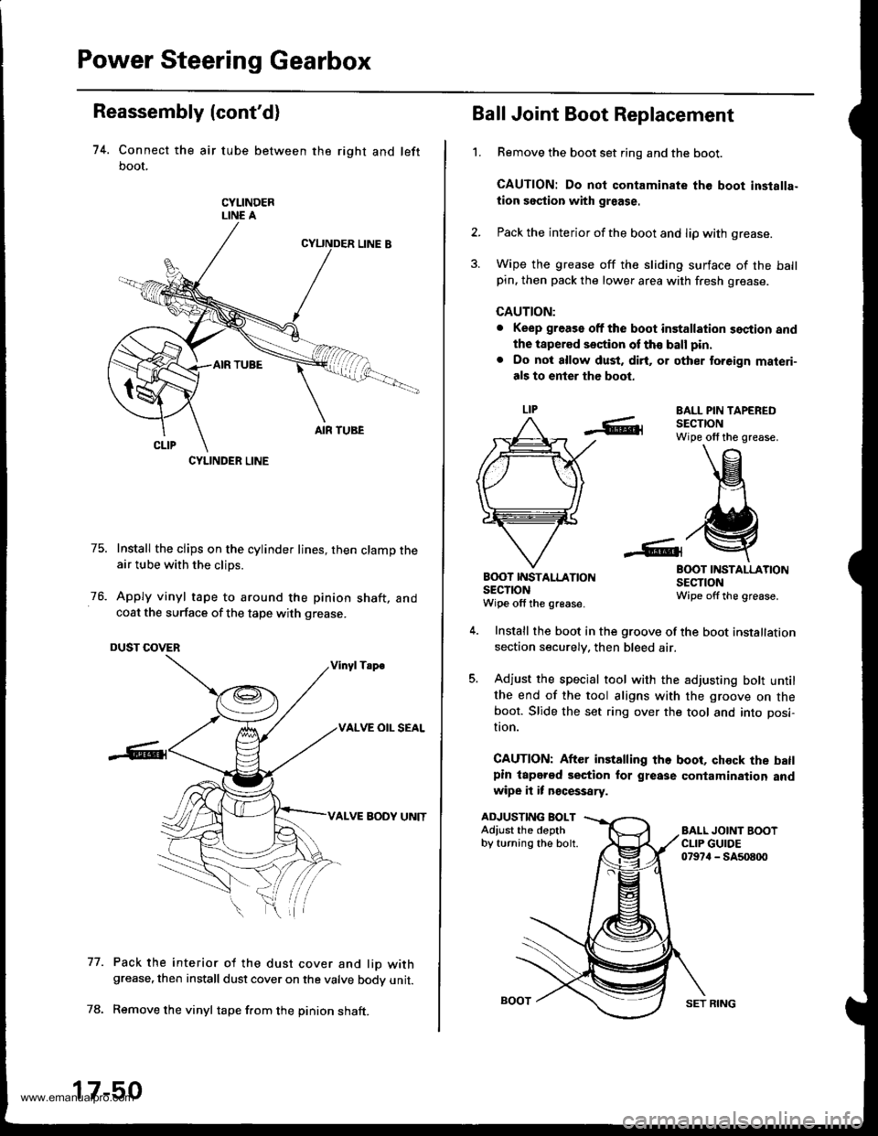
74. Connect the air tube between the right and left
boot,
CYLINDERLINE A
75. Install the clips on the cylinder lines, then clamp theair tube with the clips.
76. Apply vinyl tape to around the pinion shaft, andcoat the surface of the tape with grease.
DUST COVER
Vinyl Tsp€
VALVE OIL SEAL
VALVE BODY UNIT
Pack the interior of the dust cover and lio withgrease, then install dust cover on the valve bodv unit.
Remove the vinyl tape f.om the pinion shaft.
77.
CYLINDER LINE
17-50
SET RING
't.
Ball Joint Boot Replacement
Remove the boot set ring and the boot.
CAUTION: Do not contaminate the boot inslalla-
tion section with graase.
Pack the interior of the boot and lip with grease.
Wipe the grease off the sliding surface of the ballpin. then pack the lower area with fresh grease.
CAUTION:
. Keep grease off the boot installation section and
the tapered section of th€ ball pin.
. Do not allow dust, dirt, or other to.eign materi-
als to enter the boot.
EALL PIN TAPEREDSECTIONWipe olf the grease.
BOOT INSTALLATIONSECTIONWipe offthe grease.
B(X)T IT{STALLATIONsEclroNWipe off the grease.
ADJUSTING BOLTAdiust the depthby turning the bolt.
Install the boot in the groove of the boot installation
section securely. then bleed air.
Adjust the special tool with the adjusting bott untilthe end of the tool aligns with the groove on theboot. Slide the set ring over the tool and into posi-
I|on.
CAUTION: After installing the boot, chock the batlpin lapered section for grease contamination andwipe it it n€cessary.
www.emanualpro.com
Page 898 of 1395
't 4.
15.
Center the steering rack within its stroke.
Install the steering joint, and reconnect the steering
shaft and pinion shaft.
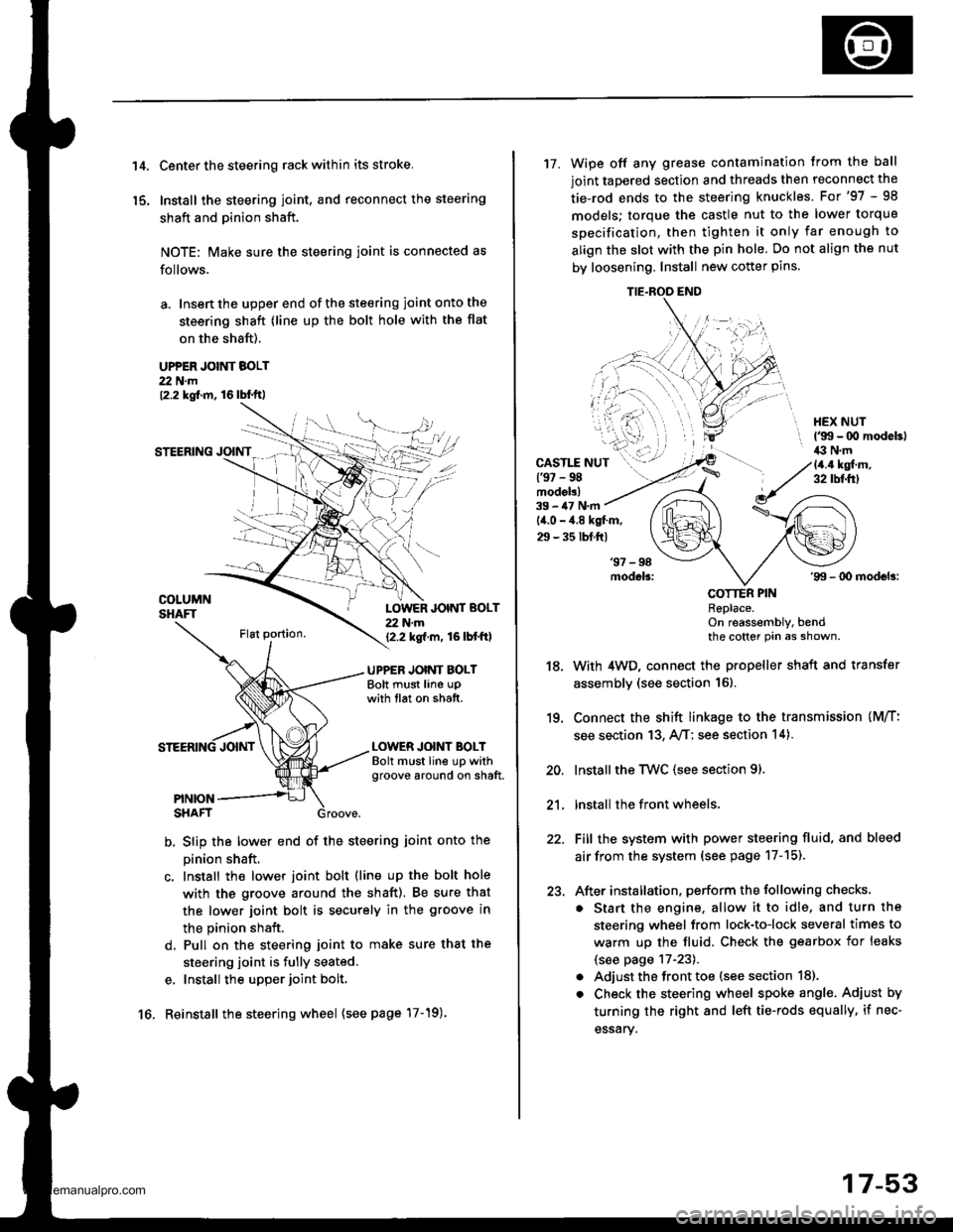
NOTE: Make sure the steering joint is connected as
follows.
a. Insen the upper end of the steering joint onto the
steering shaft (line up the bolt hole with the flat
on the shaft).
UPPER JOINT BOLT22 N.m12.2 kgf.m, 16lbl.ft,
STEERING JOINT
COLUMNSHAFTLOWER JOINT BOLT22 N.m12.2 kgf.m, 16lbtftl
UPPER JOINT BOLTBolt must line upwith tlat on shatt.
LOWER JOINT BOLTBolt must line up withgroove around on shaft.
PINIONSHAFT
b, Slip the lower end of the steering ioint onto the
pinion shaft.
c. Install the lower joint bolt (line up the bolt hole
with ths groove around the shaft). Be sure that
the lower joint bolt is securely in the groove in
the pinion shaft.
d. Pull on the steering joint to make sure that the
steering joint is fully seated.
e, Install the upper joint bolt,
Reinstall the steering wheel {see page'17-19).16.
17-53
17. Wipe off any grease contamination trom the ball
joint tapered section and threads then reconnect the
tie-rod ends to the steering knuckles. For'97 - 98
models; torque the castle nut to the lower torque
specification, then tighten it only far enough to
align the slot with the pin hole. Do not align the nut
by loosening. Install new cotter pins.
CAST1T NUT(9t - 98modol!)
HEX NUTl'g!t - 00 modeb)il:l N.m14.4 ksl.m,32 tbf.f0
39 - iU N'm
lil.o - 4.8 kgl.m,
29 - 35 tbf.ftl
18.
19.
20.
21.
22.
23.
'99 - lD modeb:
COTTER PINRePlace.on reassembly, bendthe cotter Pin as shown.
With 4WD, connect the propeller shaft and transfer
assembly (see section 16).
Connect the shift linkage to the transmission (M/T:
see section 13, A,/T; see section 14).
Installthe Twc (see section 91.
lnstall the front wheels,
Fill the system with power steering fluid, and bleed
air from the system (see page 17-15).
After installation. perform the following checks.
. Start the engine, allow it to idle, and turn the
steering wheel from lock-to-lock several times to
warm up the fluid. Check the gearbox for leaks
(see page 17-23).
. Adjust the front toe (s€e section 18).
. Check the steering wheel spoke angl€. Adjust by
turning the right and left tie-rods equally, if nec-
essary.
TIE.ROO END
www.emanualpro.com
Page 899 of 1395
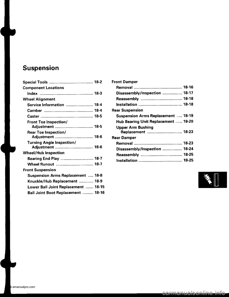
Suspension
Special Tools ............. 18-2
Component Locations
lndex ................ ...... 18-3
Wheel Alignment
Service lnformation ......................,.. 18-4
Camber .................. 18-4
Caster ............... ...... 18-5
Front Toe Inspection/
Adiustment ........ 18-5
Rear Toe Inspection/
Adiustment ........ 18-6
Turning Angle Inspection/
Adiustment ........ 18-6
Wheel/Hub Inspection
Bearing End Play .......................,...... 18-7
Wheel Runout ....... 18-7
Front Suspension
Suspension Arms Replacement ..... 18-8
Knuckle/Hub Replacement ............. 18-9
Lower Ball Joint Replacement ....... 18-15
Ball Joint Boot Replacement .......... 18-16
Front Damper
Removal ................. 18-16
Disassembly/lnspection .................. 18-1 7
Reassembly ........... 18-18
lnstallation ............. 18-18
Rear Suspension
Suspension Arms Replacement ..... 18-19
Hub Bearing Unit Replacement ...... 18-20
Upper Arm Bushing
Replacement ..... 18-23
Rear Damper
Removal ................. 18-23
Disassembly/1nspection .................. 18-24
Reassembly ........... 18-25
lnstallation ............. 18-25
www.emanualpro.com
Page 900 of 1395
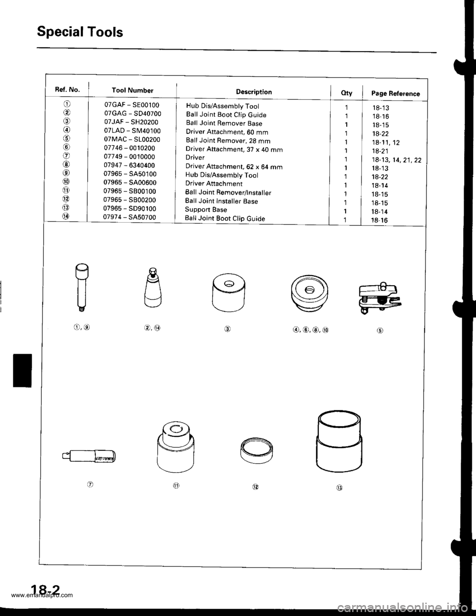
SpecialTools
Ref. No. I Tool Number
o
/a
@/6
lol
o
@6r
@
o
@
@
@
07GAF - SE00l00
07GAG - SD40700
07JAF - SH20200
07LAD - SM40100
07MAC - S100200
07746 - 0010200
07749 - 0010000
07947 - 6340400
07965 - SA50100
07965 - 5400600
07965 - S800100
07965 - S800200
07965 - SD90100
07974 - SA50700
Hub Dis/Assembly Tool
Ball Joint Boot Clip GuideBall Joint Remover Base
Driver Attachment, 60 mm
Ball Joint Remover,23 mmDriver Attachment,3T x 40 mmDriver
Driver Attachment, 62 x 64 mmHub Dis/Assembly Tool
Driver Attachment
Ball Joint Remover/lnstaller
Ball Joint Installer Base
Support Base
Ball Joint Boot Clip Guide
1
1
1
1
1
1
1
1'l
I
1
1
I
1
r 8-'13'18 16
18-15
1A-22
1a-1't,12
1a-21
18-13, 14,21,22
18-13
1a-22
18- 14
18- 15
18-15
l8-14
18-16
c
f1
U
o,o.4.@@,@,@,@
oo@c0
18-2
www.emanualpro.com
Page 902 of 1395
Wheel Alignment
Caster
For proper inspection/adjustment of the wheel align-ment, check and adjust these items before checkinq thealignment:
. Check that the suspension is not modified.. Check the tire size and tire pressure.
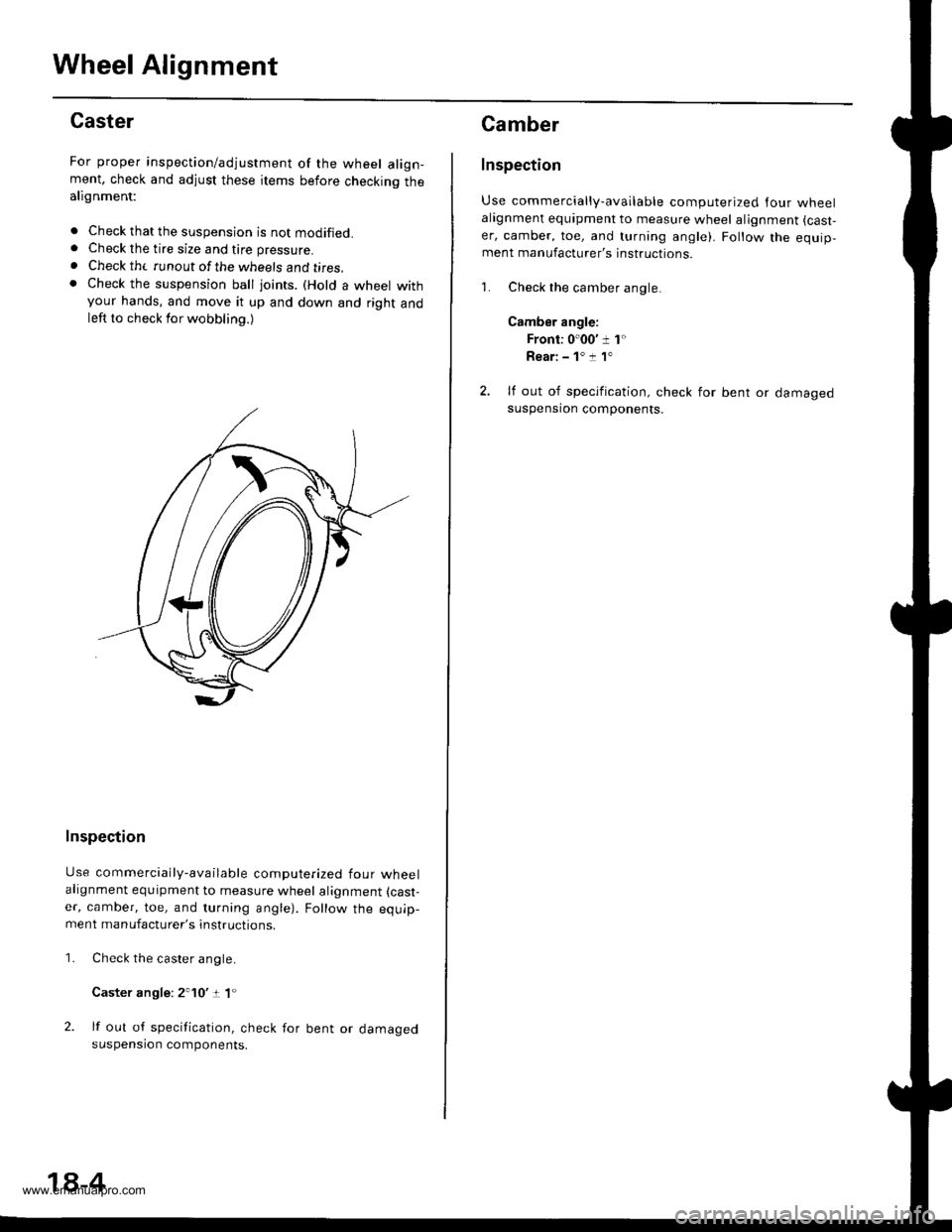
. Check th( runout of the wheels and t;res,. Check the suspension ball joints. (Hold a wheel withyour hands, and move it up and down and right andleft to check for wobbling.)
Inspection
Use commercially-available computerized four wheelalignment equipment to measure wheel alignment (cast-
er, camber, toe, and turning angle). Follow the equip-ment manufacturer's instructions.
Check the caster angle.
Caster angle: 2'10':t 1"
lf out of specification, check for bent or damagedsuspension components.
1.
18-4
Camber
Inspection
Use commercially-available computerized lour wheelalagnment equipment to measure wheel alignment (cast,
er, camber, toe, and turning angle). Follow the equip,ment manufacturer's instructions.
1. Check the camber angle.
Camber angle:
Front: 0'00' 1 1"
Rear: - 1' :! 1"
2. lf out of specification, check for bent or damagedsuspensron components.
www.emanualpro.com
Page 906 of 1395
Front Suspension
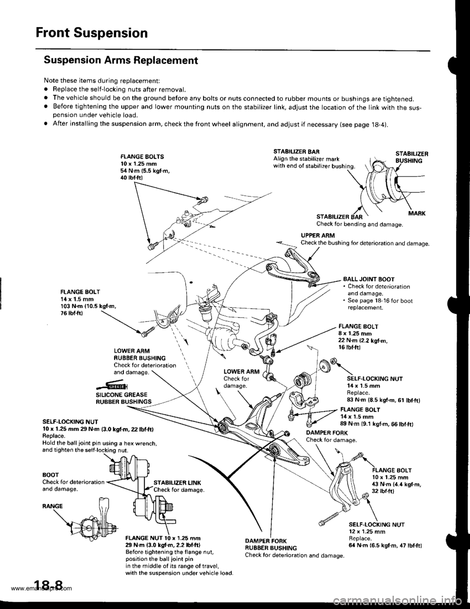
Suspension Arms Replacement
Note these items during replacement:
. Replace the self-locking nuts after removal.
. The vehicle should be on the ground before any bolts or nuts connected to rubber mounts or bushings are tightened.. Before tightening the upper and lower mounting nuts on the stabilizer link, adjusr the location of the link with the sus-pension under vehicle load.
. After insta lling the suspension arm, check the front wheel alignment, and adjust if necessary (see page 18-4|.
FLANGE EOLTS10 x 1.25 mm54 N.m (5.5 kgf.m,40 tbf.ft)
STABILIZER LINKCheck for daftage.
FLANGE BOLT8 x 1.25 mm22 N.m {2.2 kg{.m,16 tbf.ftl
STAEILIZER
AOLT
STABILIZER BARAlign the stabilizer markwith end of stabilizer bushing.
STABILIZERCheck for bending and damage.
UPPER ARMCheck the bushing for deterioration and damage.
FLANGE BOLT1{ x 1.5 mm103 N.m {10.5 kgf.m,76 tbf.ft)
BALL JOINT BOOT. Check for deter'orationano oamage,See page 18 16 for bootreplacement.
LOWER ARMRUBBER BUSHINGCheck for deteriorationand damage.
..'.{l@3
SILICONE GREASERUBBER BUSHINGS
SELF-LOCKING NUT10 x 1.25 rr|m 29 N.m (3.0 kgf.m, 22 lbf.ft)Feplace.Hold the ball ioint pin using a hex wrenct
BOOTCheck for deteriorationano oamage,
29 N.m {3.0 kgl.m, 2.2 lbf.ftlBefore tightening the llange nut,position the ballioint pinin the middle of its range of travel,with the suspension under vehicle load.
DAMPER FORKRUBBER BUSHINGCheck for deterioration and damage.
o\
DAMPER FOBKCheck for damage.
SELF.LOCKING NUT14 x 1.5 mmReplace.83 N.m (8.5 kgt.m, 61 lbt.ftl
FLANGE BOLT14 x 1.5 mm89 N.m (9.'l kgl.m, 66 tbf.ft)
10 x 1.25 mm!$ N.m (4.4 kgt.m,32 rbf.ftl
SELF.LOCKING NUT12 x 1.25 mmBeplace.64 N.m (6.5 kgt.m, 47 lbf.ft)
18-8
www.emanualpro.com
Page 907 of 1395
Knuckle/Hub Replacement
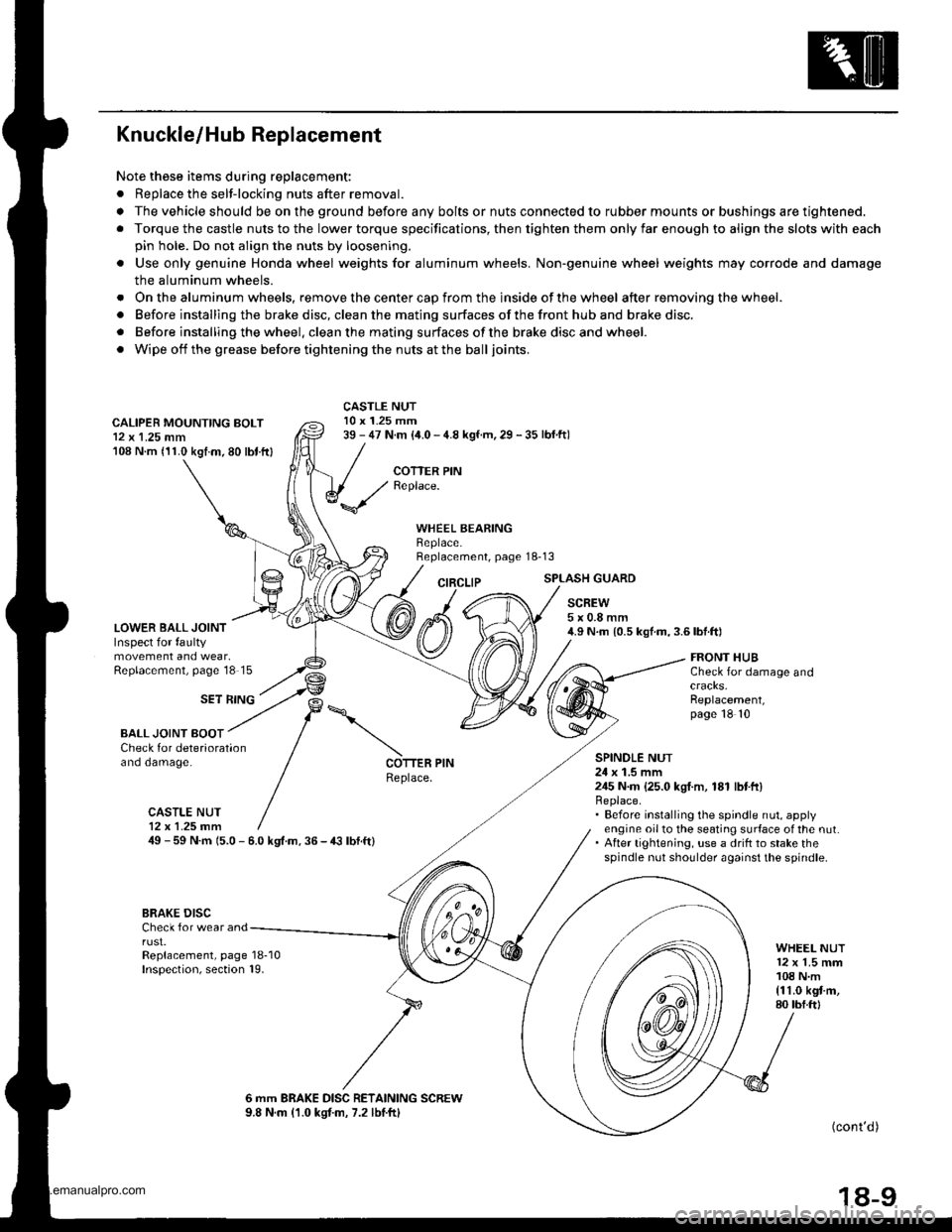
Note these items during replacement:
. Replace the selt-locking nuts after removal.
. The vehicle should be on the ground before any bolts or nuts connected to rubber mounts or bushings are tightened.
. Torque the castle nuts to the lower torque specifications, then tighten them only far enough to align the slots with each
pin hole. Do not align the nuts by loosening.
o Use only genuine Honda wheel weights for aluminum wheels. Non'genuine wheel weights may corrode and damage
the aluminum wheels.
. Onthealuminum wheels, remove the center cap from the inside of the wheel after removing the wheel.
. Before installing the brake disc, clean the mating surfaces of the front hub and brake disc.
. Before installing the wheel. clean the mating surfaces ofthe brake disc and wheel.
. Wipe off the grease before tightening the nuts at the balljoints.
CALIPER MOUNTING BOLT12 x 1.25 mm108 N.m (11.0 kgtm.80 lbt.ftl
LOWER BALL JOINTInspect for faultymovement and wear,Replacement, page'18 15
CASTLE NUT10 x 1.25 mm39 - 47 N.m (i1.0 - 4.8 kgf.m, 29 - 35 lbf.ftl
COTTER PINReplace.
WHEEL BEARINGBeplace.Replacement, page 18-13
CIRCLIPSPLASH GUARD
SCREW5x0.8mm4.9 N.m {0.5 kgf.m,3.6lbf.ft)
SET RING
FRONT HUBCheck for damage and
Replacement,page 18 10
BALL JOINT BOOTCheck for deteriorationano oamage.SPINOLE NUT24 x 1.5 mm245 N.m {25.0 kgI.m, 181 lbtft}Replace.. Before installing the spindle nut, applyengine oil to the seating surface of the nut.. After tightening, use a drift to stake thespindle nut shoulder against the spindle.
COTTER PINReplace.
CASTLE NUT12x 1.25 fim49 - 59 N.m 15.0 - 6.0 kgt.m. 36 - € lbf.ft)
BRAKE DISCCheck for wear andrust.Replacement, page 18-10Inspection, section 19.
WHEEL NUT12 x 1.5 mm108 N.m{11.0 kgt m,80 tbf.ftl
6 mm BRAKE DISC RETAINING SCREW9.8 N.m (1.0 kgtm, 7.2 lbtftl(cont'd )
18-9
www.emanualpro.com
Page 909 of 1395

12.
13.
14.
Clean any dirt or grease off the ball joint.
Remove the cotter pin from the steering arm, and
remove the nut.
Apply grease to the special tool on the areas shown.
This will ease installation of the tool and prevent
damage to the pressure bolt threads.
PRESSURE BOLT
lnstall a 10 mm hex nut on the ball joint. Make sure
the hex nut is flush with the ball joint pin end to
prevent damage to the threaded end of the ball
joint.
BALL JOINT REMOVER, 28 mm07MAC - SL(x)2(x)HEX NUT
HEX NUT10 x 1.25 mm('99 modcll43 N.mlit.a kgl.m.32 tbtft)
37 -98 models:
tc.
6:)
CASTLE NUT10 x '1.25 mm
l'97 - 98 modcls)39 - 47 N.m{4.0 - 4.829 - 3s rbtftt
COTTERReplace.On re6ss€mbly,bend the cofter pin
16. Install the special tool as shown. Insert the jaws
carefully, making sure you do not damage the balljoint boot. Adiust the jaw spacing by turning the
pressure bolt. lf necessary, apply penetrating type
lubricant to loosen the ball ioint.
'99 -00 modol:
18.
17. Once the special tool is in place, turn the adjusting
bolt as necessary to make the jaws parallel. Then
hand-tighten the pressure bolt, and recheck thejaws to make sure they are still parallel.
ADJUSTING BOLT
After making the adjustment to the adjusting bolt,
make sure the head of the adjusting bolt is in this
position to allow the jaw to pivot.
With a wrench, tighten the pressure bolt until the
ball joint shaft pops loose from the steering arm.
@ wear eye protection. The balt iointcan break loose suddenly and scatter dirt or other
dsbris in your ey€s.
Remove the tool, then remove the nut from the end
of the ball joint, and pull the ball joint out of the
steering/suspension arm. Inspect the ball joint boot.
and replace it if damaged.
(cont'dl
1(|
18-1 1
www.emanualpro.com