1999 HONDA CR-V ball joint
[x] Cancel search: ball jointPage 846 of 1395

Steering
Special Toofs ............. 17-2
Component Locations
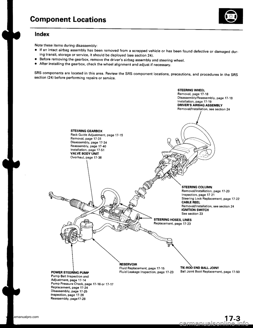
Index ................ ....... 17-3
Troubleshooting
General Troubleshooting ................ 1 7-4
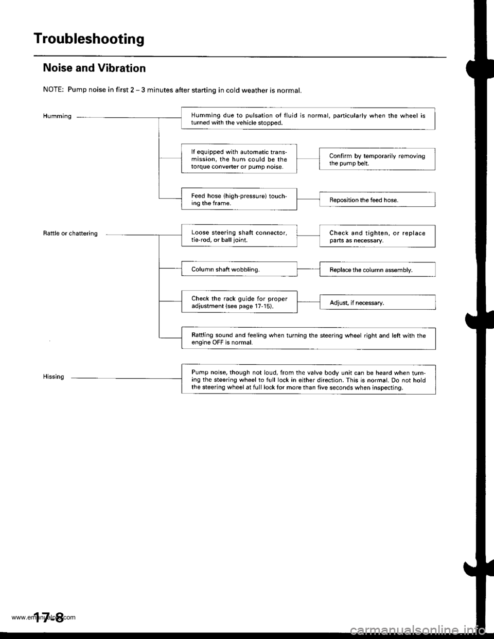
Noise and Vibration ......................... 17-8
Fluid Leaks ............. 17-10
Inspection and Adiustment
Steering Operation .......................... 17-12
Power Assist Check
With Vehicle Parked ....................
Steering Linkage and Gearbox .......
Pump Belt
Rack Guide Adjustment ...................
Fluid Rep|acement ...................,,.,....
Pump Pressure Check .................,,...
*Steering Wheel
Removal ................. 17-18
*Steering Column
Removal/lnstallation ................ ....... 17 -2O
lnspection .............. 17-21
Steering Lock Replacement ............ 17 -22
Power Steering Hoses, Lines
Ffuid Leakage Inspection ................. 17 -23
Repfacement .......... 17-23
Power Steering Pump
Repfacement .......... 17-24
Disassembly ...........17-25
fnspection .............. 17-26
Reassembly ............ 17-28
Power Steering Gearbox
Removal ................. 17-31
Disassembly ........... 17-34
Reassembly ............ 17-40
Ball Joint Boot Replacement .......... 17-50
Installation ............. 17-51
17-12
17-13
17-14
l7-15
17-15
17-16
Disassembly/Reassembly............... 17-18
4'%/b.......... -r'-7--a/
SUPPLEN\EN AL RES\RA(N SYSTES{ (SRS\
This model has an SRS which includes a driver's airbag in the steering wheel hub. a passenger's airbag in the dashboardabove the glove box ('97 - 00 models), and seat belt tensioners in the seat belt retractors ('98 - 00 models). Informationnecessary to safely service the SRS is included in this Service Manual. ltems marked with an asterisk (*) on the contentspage include, or are located near, SBS components. Servicing. disassembling or replacing these items will require specialprecautions and tools, and should only be done by an authorized Honda oearer.
To avoid rendering the SRS inoperative, which could lead to peFonal iniury or death in the event of a sevore trontalcollision. allSRS service work must be performod by an authorized Honda dealer.lmproper service procedurgs, including incorrect removal and installalion of the SRS, could lead to personal iniurycaused by unintontional deployment of th€ airbags {'97 - 00 models), and seat belt tensioners ('98 - 00 modelsl.Do not bump the SRS unit. Otherwise, the system may lail in case ot a collision, or the airbags may deploy when theignition switch is ON (lll.
SRS electrical wiring harnesses are identitied by yellow colof coding. Ralated components are located in the steeringcolumn, front console, dashboard, dashboard lower panel, and in the dashboard above the glove box. Do not use elec-trical test equipment on these cilcuits,
www.emanualpro.com
Page 847 of 1395
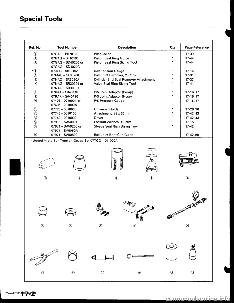
Ret. No, I Tool NumbelDescriptionfty Page Reference
o
o
-@
€r
o
@rol
@
o
@
@(}
@
@
07GAF - PH70100
07HAG - SF10100
07GAG - SD40200 or
OTGAG - SD4O2OA
07JGG - 001010A
07MAC - S100200
OTNAD _ SR3O2OA
07NAG SR30900 or
07NAG , SR3OgOA
07RAK - 50401 10
07RAK - 5040120
07406 - 0010001 or
07406 - 0010004
07725 - 0030000
07746 - 0010100
07749 - 0010000
07916 - SA50001
07974 - SA50200 or
07974 - SA5050A
07974 - SA50800
Pilot Collar
Piston Seal Ring Guide
Piston Seal Ring Sizing Tool
Belt Tension Gauge
Ball Joint Remover,23 mm
Cylinder End Seal Remover Attachment
Valve Seal Ring Sizing Tool
P/S Joint Adaptor (Pump)
P/S Joint Adaptor (Hose)
P/S Pressure Gauge
Universal Holder
Attachment, 32 x 35 mm
Driver
Locknut Wrench, 40 mm
Sleeve Seal Ring Sizing Tool
Ball Joint Boot Clip Guide
'l
1
1
1
1
1
1
1
1
1
1
1
1,l
1
1
11-39
17-44
11-44
17 -14't]-31
17 -37't7 -4'l
17-'t6, 17
17-16, 17
11-16, 17
17-26,30't]-42, 43't1-42, 43
11-15't]-42
11-42, 50
* Included in the Belt Tension Gauge Set 07TGG - 001000,4
o@
\J
,/:\
I
o
,€l-
=tt
@@
aA)
l:I/\L----.--.--------_
@o(D(9@@
17-2
www.emanualpro.com
Page 848 of 1395
Component Locations
lndex
Note these items during disassembly:' lf an intact airbag assembly has been removed from a scrapped vehicle or has been found defective or damaged dur-ing transit, storage or service. it should be deployed (see section 24),a Before removing the gearbox, remove the driver.s airbag assembly and steering wheel.. After installing the gearbox, check the wheel alignment and adjust if necessary.
SRS components are located in this area. Review the SRS component locations, precautions, and procedures an the SRssection (24) before performing repairs or servrce.
STEERING WHEELRemoval, page 17,18Disassembly/Reassembly, page 1?,18Installation, page 17-19DRIVER'S AIRBAG ASSEMBLYRemoval/lnstallation, see section 24
STEERING GEARBOXRack Guide Adjustment, page 17-15Removal, page 17-31Disassembly, page 17-34Reassembly, page 17,40Installation, page 17,51VALVE BODY UNITOverhaul, page 17-38
STEERING COLUMNRemoval/lnstallation. page 17-20Inspection, page l7 21Steering Lock Replacement, page 17 22CABLE REELRemoval/lnstallation, see section 24tcNrnoN swtTcHSee s€ction 23
STEERING HOSES, LINESReplacement. page l7-23
Pump Belt Inspection andAdjustment, pag€ t7-14Pump Pressure Check, page 17-16 ot 17-1jReplacemont, page 17-24Disassembly, pa96 17,25Inspection, page 17-26Reassembly. page17-28
RESERVOIRFluid R6placement. page 17 15Fluid Leakage lnspection, page 17-23
END BALL JOINTBallJoint Boot Replacement, page 17-50
17-3
www.emanualpro.com
Page 853 of 1395
Troubleshooting
Noise and Vibration
NOTE: Pump noise in first 2 - 3 minutes after starting in cold weather is normal.
Humming
Rattle or chattering
Humming due to pulsation of fluid is normal, particularly when the wheel isturned with the vehicle stooDed.
lf equipped with automatic trans-mission, the hum could be thetorque converter or pump noase.
Confirm by temporarily removingthe pump belt.
Feed hose (high-pressure) touch-ing the frame.Beposition the feed hose.
Loose steering shaft connector,tie-rod, or balljoint.Check and tighten, or replaceparts as necessary,
Column shaft wobbling.Roplace the column assembly.
Check the rack guide for properadjustment (see page 17-15).Adjust, if necessary.
Rattling sound and feeling when turning the steering wheel right and left with th€engine OFF is normal.
Pump noise, though not loud, from the valve body unit can be heard when turn-ing the steering wheel to full lock in either direction. This is normal. Do not holdthe steering wheel at full lock lor more than five seconds when inspecting.
17-8
www.emanualpro.com
Page 858 of 1395

Steering Linkage and Gearbox
PINION SHAFT GROMMETInspoct for damage and deterioration.
STEERING JOINTSCheck for loose joint bolts.
NE-ROD LOCKNUTCheck Ior loose locknut.
Inspect for loose mounting bolts.GEARBOX MOUNTING CUSHIONSlnsp6ct for dgterioration.BOOTlnspect for damag€ and d€terioration.
BALL JONT AOOTInspoct lor damage and deterioration.S€e page 17-50 for replacemont.
END AAtL JOINTInspect for faulty movementano oamag€.
17-13
www.emanualpro.com
Page 866 of 1395

8. Installation is the reverse ofthe removal procedure.
Note these items during installation:
. Be sure the wires are not caught or pinched by
any parts when installing the column.
a Make sure the wire harness is routed and fas-
tened properly.
. Make sure the connectors are properly connected.
. Make sure the steering joint is connected as fol-
lows:
a. lnsert the uDper end of the steering joint onto
the steering shaft (line up the bolt hole with
the flat ot the shaft).
b. Slip the lower end of the steering ioint onto
the Dinion shaft (lins up the bolt hole with the
groove around the shaft). and installthe lower
ioint bolt. Be sure that the lower joint bolt is
securely in the groove in the pinion shaft'
c. Pull on the steering joint to make sure that the
steering joint is JullY seated.
Then install the upper joint bolt and tighten it.
22 N.m (2.2 kgf.m, 16lbt.ftl
UPPER JOINT BOLT
Bolt must Iine uPwith fl6t on shaft.
Flat ponion.
SIEERING JOIMT
STECRING JOINT
LOWER JOINT BOLTBolt must line up withgroove around on shaft,
Inspection
Check the steering column ball bearing and the steer-
ing joint bearings for play and proper movement. lf
there is noisy or if there is excessive play, replace the
steering column as an assemblY
Check the retaining collar for damage. lf it is dam-
aged, replace the retaining collar.
PLASl'tCINJECTIONS
ABSOBBINGPLATE
SHIFT I.EVER
. Check the absorbing plates, absorbing plate guides
and sliding capsules Jor distortion and breakage.
ReDlace the column as an assembly if they are dis-
torted or broken.
SLIDING CAPSUIIThis part is attachedto the column bracketwith the plastic injections.
FETAINING COLLAR
ABSORBINGPLATE GUIDE
|GNMON SWTTCHSee section 23.(cont'd)
17-21
See section 14.
www.emanualpro.com
Page 876 of 1395
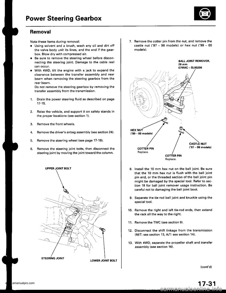
Power Steering Gearbox
Removal
Note these items during removal:
. Using solvent and a brush, wash any oil and dirt off
the valve body unit its lines, and the end if the gear-
box. Blow dry with compressed air.
. Be sure to remove the steering wheel before discon-
necting the steering joint. Damage to the cable reel
can occur.
. With 4WD. tilt the engine with a jack to expand the
clearance between the transfer assembly and rear
beam when removing the steering gearbox from the
rear oeam.
Do not remove the steering gearbox by removing the
transfer assembly from the transmission.
1. Drain the power steering fluid as described on page'17-15.
Raise the vehicle, and suppon it on safety stands in
the proper locations (see section 1).
Remove the front wheels,
Remove the drive/s airbag assembly {see section 24).
Remove the steering wheel {see page 17-18).
Remove the steering joint bolts, then disconnect the
steering joint by moving the joint toward the column.
UPPER JOINT BOLT
LOWER JOINT BOLT
13.
7. Remove the cotter pin from the nut, and remove the
castle nut {'97 - 98 models) or hex nut ('99 - 00
models).
COTTER PINReplace.
Install the 10 mm hex nut on the ball joint. Be sure
that the 10 mm hex nut is flush with the ball joint
pin end, or the threaded section of the ball joint pin
might be damaged by the special tool. Refer to sec-
tion 18 for ball joint remover usage instruction, Be
careful not to damaging the ball joint boot.
Separate the tie-rod ball joint and knuckle using the
special tool.
Remove the right and left tie-rod ends, then extend
the rack all the way to the right.
Remove the TWC (see section 9).
Disconnect the shift linkage from the transmission
(M/T: see section 13, A/T: see section 14).
With 4WD. separate the propeller shaft and transfer
assembly (see section 161.
10.
11.
(cont'd)
17-31
www.emanualpro.com
Page 887 of 1395
Power Steering Gearbox
13.
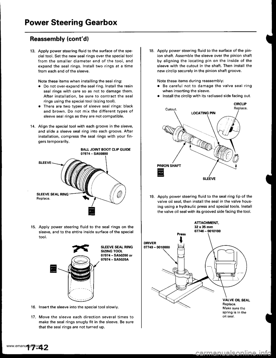
Reassembly (cont'd)
Apply power steering fluid to the surface of the spe-
cial tool. Set the new seal rings over the special tool
from the smaller diameter end of the tool. and
expand the seal rings. Install two rings at a time
Jrom each end ofthe sleeve.
Note these items when installing the seal ring:
. Do not over-expand the seal ring. Install the resin
seal rings with care so as not to damage them.
After installation, be sure to contract the seal
rings using the specialtool {sizing tool).
. There are two types of sleeve seal rings: black
and brown. Do not mix the different types of
sleeve seal rings as they are not compatible.
Align the special tool with each groove in the sleeve,
and slide a sleeve seal ring into each groove. After
installation, compress the seal rings with your fin-
gers temporarily.
BALL JOINT BOOT CLIP GUIDE07974 - SA508q)
SLEEVE
Apply power steering fluid to the seal rings on the
sleeve, and to the ehtire inside surface of the special
tool.
14.
15.
SLEEVE SEAL RINGSIZING TOOL07974 - SA502O0 or07974 - SA5020A
16.Insert the sleeve into the special tool slowly.
Move the sleeve each direction several times to
make the seal rings snugly fit in the sleeve. Be sure
that the seal rings are not turned up,
't1.
18. Apply power steering fluid to the surface of the pin-
ion shaft. Assemble the sleeve over the Dinion shaft
by aligning the locating pin on the inside of the
sleeve with the cutout in the shaft. Then install the
new circlip securely in the pinion shaft groove.
Note these items during reassembly:
. Be caretul not to damage the valve seal ring
when inserting the sleeve.
. Install the circlip with its radiused side facing out.
Apply power steering fluid to the seal ring lip of the
valve oil seal. then install the seal in the valve hous-
ing using a hydraulic press and special tools. Install
the valve oil seal with its grooved side facing the tool.
19.
ATTACHMENT,32x35mm077i16 - (x)10100
VALVE OIL SEALReplace.Make sure thespring is in theoilseal.
CIRCLIP
www.emanualpro.com