Page 1207 of 1395

BLKG401
GroundWir€ ColorComponent or Circuits Grounded
ABS indicator circuit
ABS control unit
Ashtray light
A/T gear position indicator dimming circuit
Brake fluid level switch
Clock ('98 - 00 models)
Clutch inrerlock switch (M/T)
Clutch switch (Mff)
Cruise main switch
Cruise indicator circuit
Cruise control unit
Dash lights brightness controller
Data iink connector
Daytime running rights control unit (Canada)
Front accessary socket
Gauge and indicators
Heater control panel
lgnition key light control unit ('97 model)
lgnition key switch
Integrated control unit
Interlock control unit (Ay'T)
Parking pin switch {A,/T)
Power window relay
Rear accessary socket relay
Bear window defogger relay
Rear window wiper control unit ('97 model)
Service check connector
Spotlights
SRS indicator circuit
Turn signal/hazard relay
Windshield wiper motor
Windshield wiper/washer switch- plus everything grounded through G402
ABS control unit
Blower motor relay
Blower motor high relay
ELD unit (USA)
Power transistor- plus everything grounded through G401
BLKG402
{cont'd)
23-47
www.emanualpro.com
Page 1241 of 1395

Adjustment
Bstore adiusting the headlights:
. Park the vehicle on level ground
. Make sure the fuel tank is tull
. The driver or someone who weighs the same should
sit in the driver's seat.
. Load the trunk with the items you usually carry'
. Push down on the front and rear bumpers several
times to make sure the vehicle is sitting normally'
CAUTION: Halogen headlights become very hot in use;
do not touch them or the atiaching hardware immedi-
ately after they have been turned off.
1. ODen the hood.
2. Remove the left inner fender {see section 20).
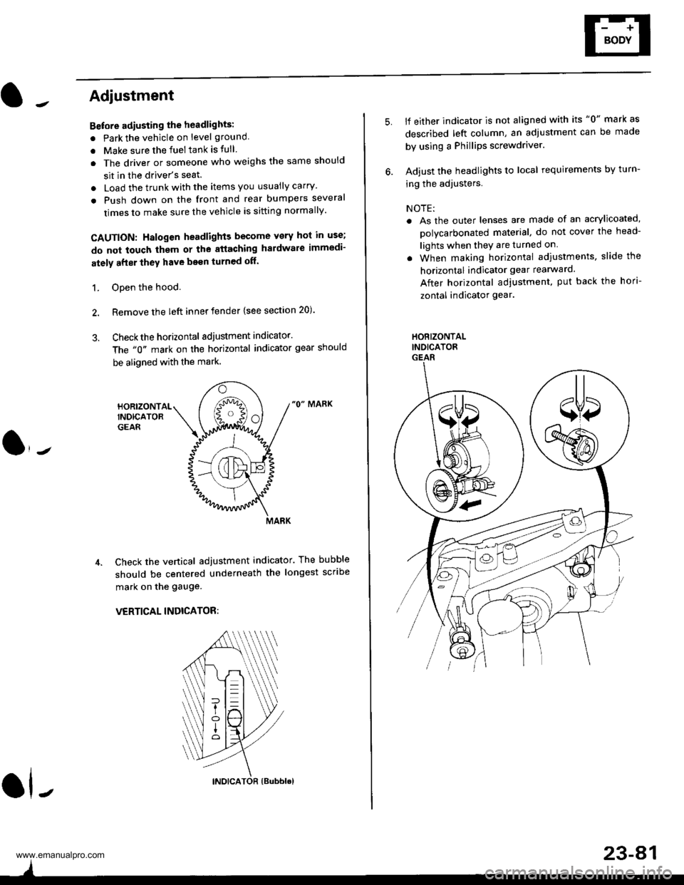
3. Checkthe horizontal adjustment indicator.
The "0" mark on the horizontal indicator gear should
be aligned with the mark.
"0" MARK
Check the vertical adjustment indicator. The bubble
should be centered underneath the longest scribe
mark on the gauge.
VERTICAL INDICATOR:
ol-
)
5.lf either indicator is not aligned with its "0" mark as
described left column, an adjustment can be made
by using a Phillips screwdriver.
Adjust the headlights to local requirements by turn-
ing the adjusters.
NOTE:
. As the outer lenses are made of an acrylicoated,
polycarbonated material, do not cover the head-
lights when they are turned on
. When making horizontal adiustments, slide the
horizontal indicator gear rearward.
After horizontal adjustment, put back the hori-
zontal indicator gear.
HORIZONTALINDICATORGEAR
23-A1
www.emanualpro.com
Page 1242 of 1395
Rear Side Marker Lights/
License Plate LightTaillights
Replacement
Rear Side Marke. Light:
1. Remove the retaining spring, and remove the rearside marker light from the rear bumper.
2. Disconnect the 2P connector from the light.
RETAINING
HOUSING
Licens€ Plate Light:
1. Remove the two screws from the license plate light,and pull the light out part of the way.
2. Disconnect the 2P connector from the light,
23-A2
LIGHT (8 WI
Replacement
1. Open the hatch glass.
2. Disconnect the 6P connector from the taillight.
3. Remove the three screws, then pull out the outertaillight.
Brak€/Plrking light 2115 W
Back-up light: 21CP (18 W)
Turn signll light 21 W
Inspect the gasket; replace it if it is distorted or$ays compressed.
Install the taillight, and run water over it to makesure it does not leak.
www.emanualpro.com
Page 1252 of 1395
Interior Lights
Component Location Index
SPOTLIGHTSTest, page
DRIVER'S DOOR SWITCH
LEFT REARoooR swtTcH
FRONT CEILING LIGHTTest, page 23-94
FRONT PASSENGER'SDOOR SWITCH
REAR CCILING LIGI{TTest, page 23-94
RIGHT REARswtTcH
HATCH GLASSLATCH SWITCH
TAILGATELATCH SwlTCH
23-92
www.emanualpro.com
Page 1262 of 1395

Stereo Sound System
Audio Unit Removal
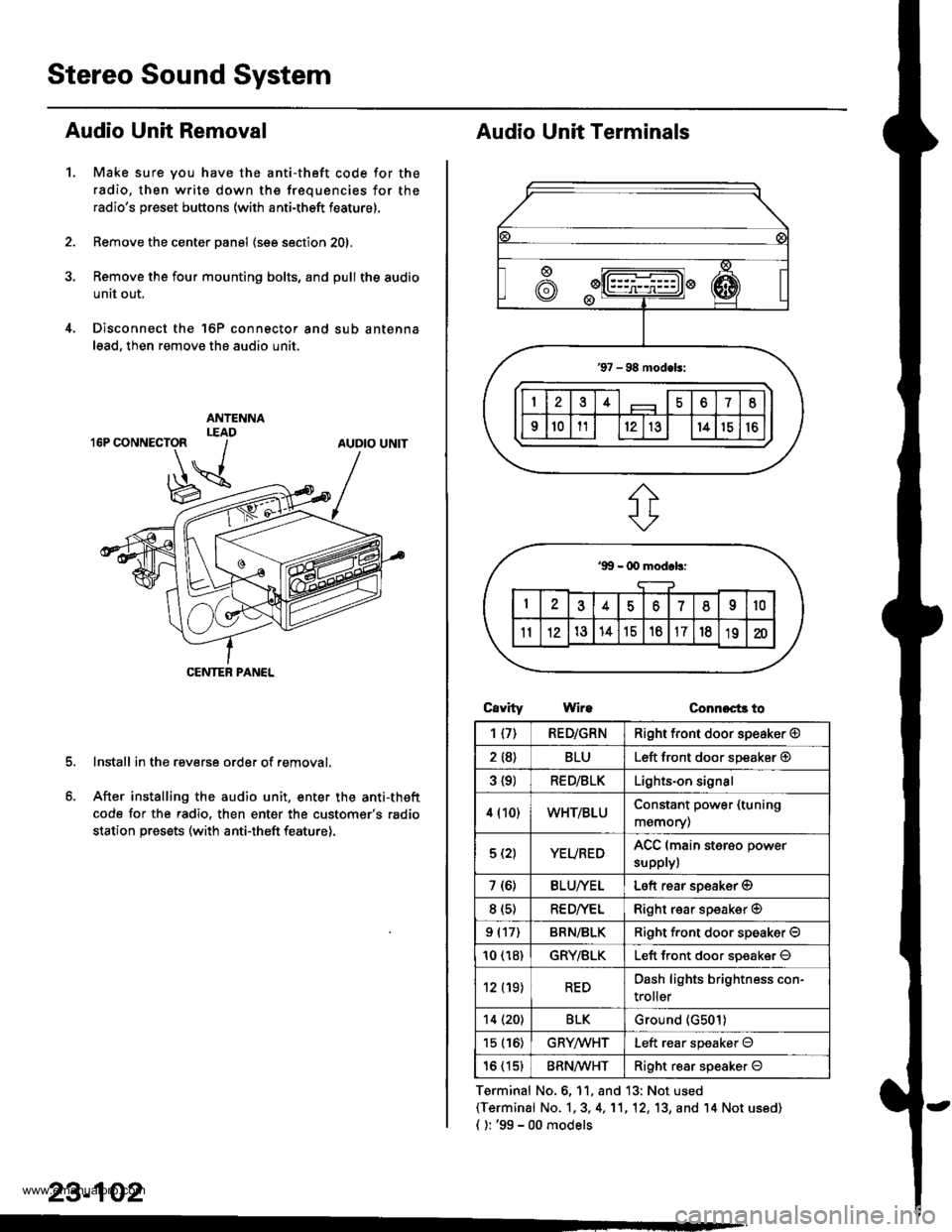
Make sure you have the anti-theft code for the
radio, then write down the frequencies for the
radio's preset buttons (with anti-theft feature).
Remove the center panel (see section 201,
Remove the four mounting bolts, and pull the audio
unit out.
Disconnect the 'l6P connector and sub antenna
lead, then remove the audio unit.
Install in the reverse order of removal.
After installing the audio unit, enter the anti-theft
code for the radio. then enter the customer's radio
station presets (with anti-theft feature).
1.
AUDIO UNIT
CENTEB PANEL
23-102
Audio Unit Terminals
CavrtyWireConnoct3 to
Terminal No.6, 11, and 13: Not used(Terminal No. 1,3, 4,'11,12, 13, and '14 Not us6d)
{ ): '99 - 00 models
1{7)RED/GRNRight front door speaker @
2 {8}BLULeft front door speaker @
3 {9)RED/BLKLights-on signal
4 (10)WHT/BLUConstant power (tuning
memory)
5 (2)YEUREDACC (main sterso power
supplyl
7 (6)BLU/YELLeft rear soeaker @
8 (s)RE D/VELRight rear speaker @
9 (17)BRN/BLKRiqht f.ont door speaker O
10 (18)GRY/BLKLeft front door soeaker O
12 (19)REDDash lights brightness con-
troller
14 (20)BLKGround (G501)
15 (16)GRYMHTLeft rear speaker O
16 (15)BRN^ll/HTRight resr speaker O
www.emanualpro.com
Page 1295 of 1395

-
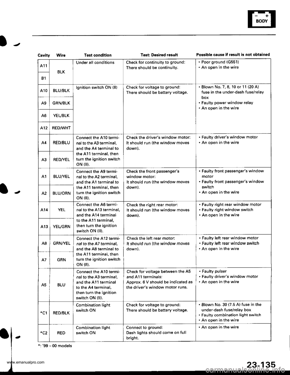
CavityWi1€Test conditionTesi: Dssired rosultPo$ible cause if 183uh is not obtained
A11
BLK
Under all conditionsCheck for continuity to ground:
There should be continuity.
. Poor ground (G551)
. An open in the wire
B1
A10BLU/BLKlgnition switch ON (ll)Check for voltage to ground:
There should be battery voltage.
Blown No. 7, 8, 10 or l1 (20 A)
fuse in the under-dash fuse/relay
box
Faulty power window relay
An open in the wire
A9GRN/BLK
A6YEUBLK
412RED/WHT
A4RE D/BLU
Connect the A10 termi-
nal to the 43 terminal,
and the A4 terminal to
the A11 terminal, then
turn the ignition switch
oN flr).
Check the driver's window motor:
It should run (the window moves
down).
. Faulty driver's window motor
. An open in the wire
A3RED/YEL
A1BLUI/EL
Connect the A9 termi-
nal to the A2 terminal,
and the Al terminal to
the 411 terminal, then
turn the ignition switch
oN flr).
Check the front Passenger'swindow motor:
It should run (the window moves
down).
Faulty front passenger's window
motor
Faulty front passenger's window
switch
An open in the wireA2BLU/ORN
A14YEL
Connect the 46 termi-
nalto the A13 terminal,
and the 414 terminal
to the A11 terminal,
then turn the ignition
switch ON (ll).
Check the right rear motor:
It should run (the window moves
oown).
Faulty right rear window motor
Faulty right window switch
An open in the wire
YEUGRN
A8GBN/YEL
Connect the A12 termi-
nal to the A7 terminat,
and the A8 terminal to
the A11 terminal. then
turn the ignition switch
oN flr).
Check the left rear motor:
,t should run {the window moves
down),
Faulty left rear window motor
Faulty ,eft rear window srrvitch
An open in the wire
GRN
A5BLU
Connect the A10 te.mi-
nal to the 43 terminal,
and the A11 terminal
to the 44 terminal.
then turn the ignition
switch ON (ll).
Check for voltage between the A5
and Al l terminals:
ADorox.6 V should be indicated as
the driver's window motor runs.
Faulty pulser
Faulty driver's window motor
An open in the wire
*clRED/BLK
Combination light
switch ON
Check fo. voltage to ground:
There should be battery voltage.
Blown No.30 (7.5 A) fuse in the
under-dash fuse/relay box
Faulty combination light switch
An open in the wire
RED
Combination light
switch ON
Connect to ground:
Dash lights should come on full
bright.
' An open in the wire
www.emanualpro.com
Page:
< prev 1-8 9-16 17-24