Page 861 of 1395

lnspection and Adjustment
Pump Pressure Gheck With T/N 07406 - 0010001
Check the fluid pressure as follows to determine whetherthe trouble is in the pump orgearbox.
1. Check the powsr steering fluid level (see page 17-15), and pump belt tension (see page 17-14).
2. Disconnect the pump outlet hose from the pump
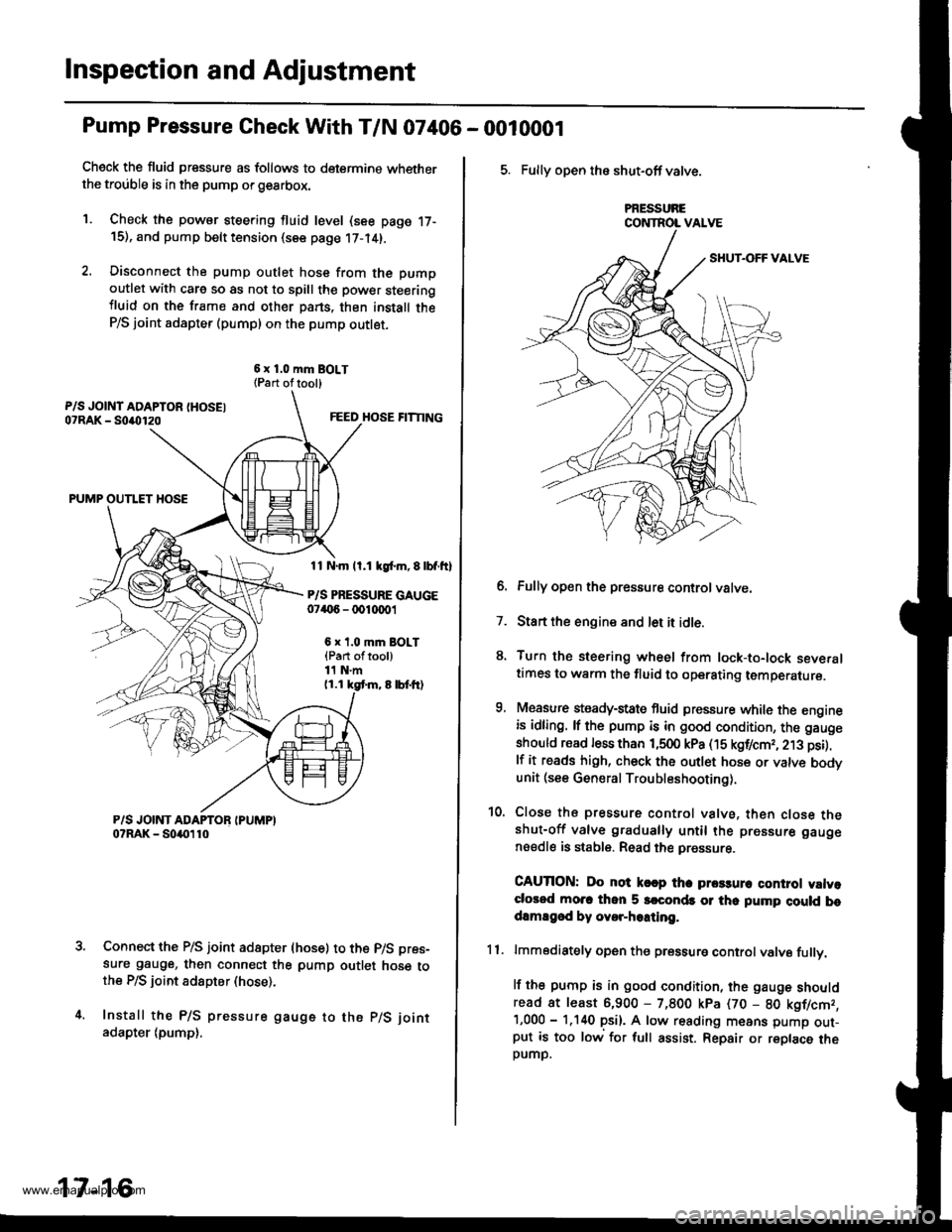
outlet with care so as not to spill the pow€r steeringiluid on the frame and other pans. thon install theP/S joint adapter (pumpl on the pump outlet.
6 x 1.0 mm BOLT{Part oftool)
FEED HOSE FITTING
PUMP OUTLET HOSE
11 N.m ll.1 kgl.m, E lbf.ftl
P/S PRESSURE GAUGE07('6 - 0010001
6 x t.0 mm BOLT{Part oftool)11 N.m(1.1 kgt m, 8 lbf.tr)
Connect the P/S joint adapter (hose) to the p/S pres-
sure gauge, then connect the pump outlet hose tothe P/S ioint adspter (hose).
Install the P/S pressure gauge to the p/S joint
adapter (pump),
17-16
5. Fully open the shut-off valve.
PRESSURECONTROL VALVE
6. Fully open the pressure controlvatve.
7. Start the engine and let it idle.
8. Turn the steering wheel from lock-to-lock severaltimes to warm the fluid to operating temperature.
9, Measure steady-state fluid pressure while the engineis idling. lf the pump is in good condition, the gauge
should read less than 1,500 kPa (15 kgf/cmr, 213 psi).
lf it reads high, check the outlet hose or valve bodvunit (see General Troubleshooting).
10. Close the pressure control valve, then close theshut-off valve gradually until the pressure gauge
nsedle is stable. Read the pressure.
CAUTION: Do not k€ap tha prca3un control valvoclorod mo.c thon 5 srconds or thc pump cluld bodamEgod by ovor-hoating.
11. lmmodiately open the pressure controlvalve fullv.
lf the pump is in good condition, the gauge shouldread at least 6,900 - 7,800 kpa (70 - 80 kgflcmr,'1,000 - 1.140 psi). A low reading means pump out-put is too low for full assist. Repair or replace theDUMD.
www.emanualpro.com
Page 903 of 1395

Front Toe Inspection/Adjustment
Use commercially-available computerized four wheel
alignment equipment to measure wheel alignment (caster,
camber, toe, and turning angle). Follow the equipment
manufacturer's instructions,
3.
1.Check the tire pressure.
Center the steering wheel spokes.
Check the toe with the wheels pointed straight
ahead.
Front toe-in: 0 i 3 mm {0 t 1/8 inl
- lf adjustment is required, go on to step 4.
- lf no adjustment is required, remove alignment
equipment.
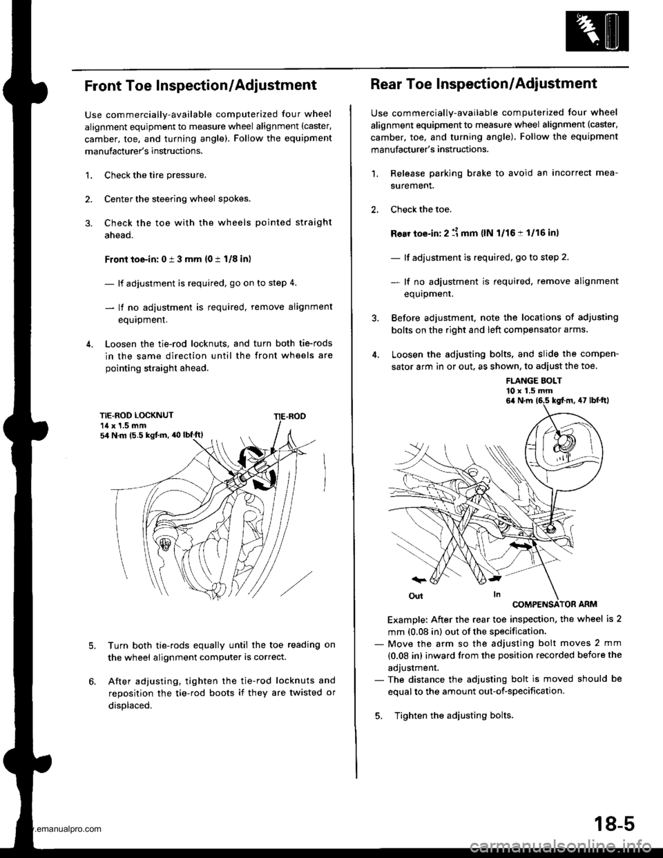
Loosen the tie-rod locknuts, and turn both tie-rods
in the same direction until the front wheels are
pointing straight ahead.
5.Turn both tie-rods equally until the toe reading on
the wheel alignment computer is correct.
After adjusting, tighten the tie-rod locknuts and
reposition the tie-rod boots if they are twisted or
displaced.
sir N m (5.5 kgJ.m, 'O lbf.ft)
Rear Toe Inspection/Adjustment
Use commercially-available computerized four wheel
alignment equipment to measure wheel alignment (caster,
camber. toe, and turning angle). Follow the equipment
manufacturer's instructions.
Release parking brake to avoid an incorrect mea-
surement.
Check the toe.
Ro8r toe-in: 2 :1 mm {lN l/16:t 1/16 in,
- lf adjustment is required, go to step 2.
- lf no adiustment is required. remove alignment
equrpmenr.
Before adjustment, note the locations of adjusting
bolts on the right and left compensator arms.
Loosen the adjusting bolts, and slide the compen-
sator arm in or out. as shown, to adiust the toe.
1.
FLANGE BOLT'10 x 1.5 mm
COMPENSATOR ARM
Example: After the rear toe inspection, the wheel is 2
mm (0.08 in) out of the specification.- Move the arm so the adjusting bolt moves 2 mm
{0.08 in) inward from the position recorded before the
adjustment.- The distance the adjusting bolt is moved should be
equal to the amount out-of-specification.
5. Tighten the adjusting bolts.
6a N.m 16.5 kgf.m, 47 lbf'ftl
18-5
www.emanualpro.com
Page 1221 of 1395
Removal
'1. Remove the two screws from the instrument panel.
2. Remove the instrument panel carefully to avoid damaging the clips.
3. Tilt the steering wheel down with the tilt adjustment lever.
4, Spread a protective cloth over the steering column.
5. Remove the four mounting screws from the gauge assembly.
6. Pullthe gauge assembly out, and disconnect all connectors from it.
7, Remove the gauge assembly.
GAUGE ASSEMELY
INSTRUMENT PANEL
23-61
www.emanualpro.com
Page 1322 of 1395

)Steering-related Precautions
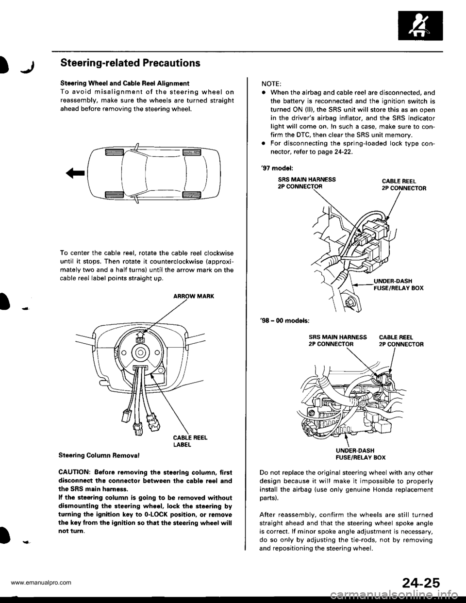
Stooring Wh€el and Csble Re6l Alignm€nt
To avoid misalignment of the steering wheel on
reassembly, make sure the wheels are turned straight
ahead beJore removing the steering wheel.
To center the cable reel, rotate the cable reel clockwise
until it stops, Then rotate it counterclockwise (approxi-
mately two and a half turns) until the arrow mark on the
cable reel label points straight up.
Steering Column Bemoval
CAUTION: Before removing the stosring column, tirsi
disconneqt tha connsctor between tho cabls roel and
the SRS main harness.
lf the steering column is going to be removed without
dismounting the steering wheel, lock the sieering by
turning the ignition key to o-LOCK position, or remove
the key trom the ignition so that the steering wheel will
not turn.
LABEL
NOTE:
. When the airbag and cable r6el are disconnected, and
the battery is reconnected and the ignition switch is
turned ON (ll), the SRS unit will store this as an open
in the driver's airbag inflator, and the SRS indicator
light will come on, In such a case, make sure to con-
firm the DTC, then clear the SRS unit memory.
. For disconnecting the spring-loaded lock type con-
nector, refer to page 24-22.
'97 model:
SRS MAIN HARNESS2P CONNECTORCABLE REEL2P CONNECTOR
'98 - 00 models:
UNDER-DASHFUSE/RELAY BOX
Do not replace the original steering wheel with any other
design because it will make it impossible to properly
install the airbag (use only genuine Honda replacement
partsl.
After reassemblv, confirm the wheels are still turned
straight ahead and that the steering wheel spoke angle
is correct. lf minor spoke angle adjustment is necessary,
do so only by adjusting the tie-rods, not by removing
and repositioning the steering whee .
24-25
www.emanualpro.com
Page 1390 of 1395

)o
NOTE:
. Before installing the steering wheel, the front
wheels should be aligned straight ahead.
. Be sure to install the harness wires so that they
are not pinched or interfering with other parts.
. After reassemblv, confirm that the wheels are
still turned straight ahead and that the steering
wheel spoke angle is correct (road test). lf minor
spoke angle adjustment is necessary, do so only
by adjusting the tie-rods, not by removing and
repositioning the steering wheel,
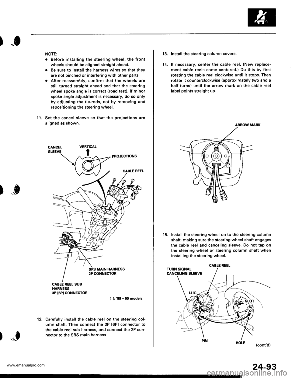
11. Set the cancel sleeve so that the projections are
aligned as shown.
PR(NECNONS
I l: 38 - 00 models
Carefully install the cable reel on the steering col-
umn shaft. Then connect the 3P t6Pl connector to
the cable reel sub harness, and connect the 2P con-
nector to the SRS main harness.
RIC
t
VEAL
)...0
't2.
24-93
13.
14.
Install the steering column covers.
lf necessary, center the cable reel. {New replace-
ment cable reels come centered,l Do this by first
rotating the csble reel clockwise until it stops, Then
rotate it counterclockwise (approximately two and a
half turns) until the arrow mark on the cable reel
label points straight up.
Install the steering wheel on to the steering column
shaft, making sure the steering wheel shaft engages
the cable reel and canceling sl€eve. Do not tap on
the steering wheel or steering column shaft when
installing the steering wheel.
(cont'd)
t5.
CABLE REEL
www.emanualpro.com