Page 943 of 1395

10.
11,
Connect the parking brake cable to the parking
brake lever,
Clean the threaded portions of clevises A and B.
Coat the threads of the clevises with grease. To
shorten the clevises, turn the adiuster bolt.
Hook the self-adjuster spring to the self-adjuster
lever first, then to the brake shoe,
Install the clevises and upper return spring noting
the installation direction. Be careful not to damage
the wheel cylinder dust covers.
Installthe lower return spring.
12.
14.
UPPER RETURN SPRING
Apply rubber greaseto sliding surface.
15. Apply grease on each sliding surface. Keep grease
or oil off the brake linings. Wipe any excess grease
off the parts.
. Apply brake cylinder grease (P/N: 08733 - 8020E)
or equivalent rubber grease to the sliding sur-
faces as shown.
..4 Slrdrng surface
Apply Molykote 44MA to the brake shoe ends
and opposite edges of the shoes as shown.
.. a Opposite edge of the shoe.: a) Brake shoe ends(Shoe side ends and backingplate contact surface)
(cont'd)
www.emanualpro.com
Page 1012 of 1395
7.
8.
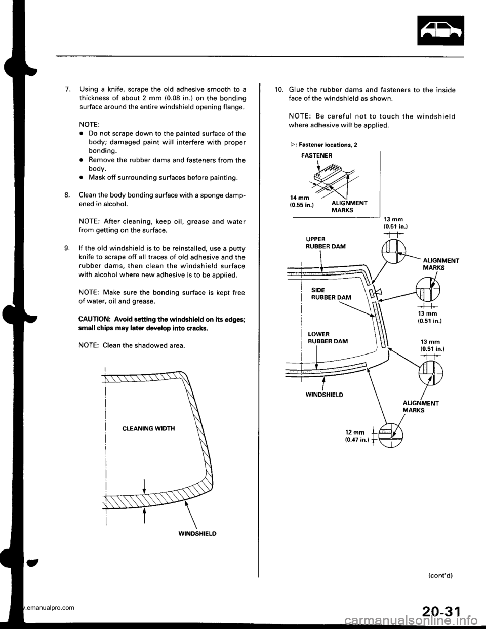
Using a knife, scrape the old adhesive smooth to a
thickness of about 2 mm (0.08 in.) on the bonding
surface around the entire windshield opening flange.
NOTE:
a Do not scrape down to the painted surface of the
body; damaged paint will interfere with proper
bonding.
. Remove the rubber dams and fasteners from the
oooy,
. Mask off surrounding surfaces before painting.
Clean the body bonding surface with a sponge damp-
ened in alcohol.
NOTE: After cleaning, keep oil, grease and water
from getting on the surface.
lf the old windshield is to be reinstalled, use a putty
knjfe to scrape off all traces of old adhesive and the
rubber dams, then clean the windshield surface
with alcohol where new adhesive is to be applied.
NOTE: Make sure the bonding surface is kept free
of water, oil and grease.
CAUTION: Avoid setting tho windshield on its edges;
small chips m8y later devolop into cracks.
NOTE: Clean the shadowed area.
9.
WINDSHIELD
10. Glue the rubber dams and fasteners to the inside
face of the windshield as shown
NOTE: Be careful not to touch the windshield
where adhesive will be applied,
13 mm(0.51 in.)--r-r
>r Fastener locrtions. 2
FASTENEB
\,@,--
w,{,.'>Yl
14 mm -'- \l0.55 in.l ALIGNMENTMARKS
ALIGNMENTMARKS
13 mm(0.51 in.l
13 mm10.51 in.)*ffi
ALIGNMENTMARKS
12 mm(0.47 in.l
(cont'd)
20-31
www.emanualpro.com
Page 1014 of 1395
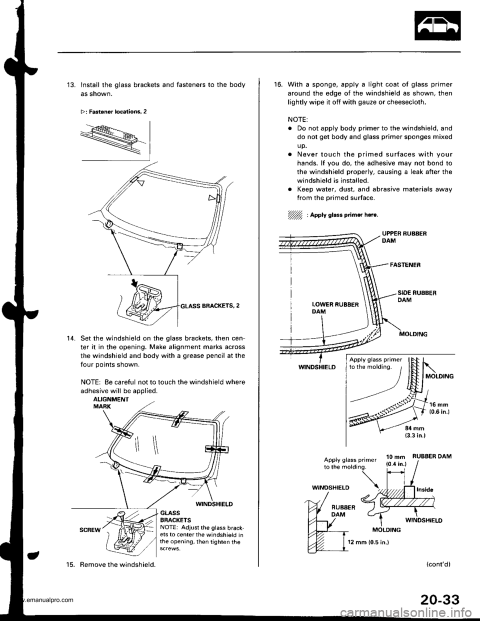
'13. Install the glass brackets and fasteners to the body
as shown.
>: Fastener locations, 2
R-
14. Set the windshield on the glass brackets. then cen
ter it in the opening. Make alignment marks across
the windshield and body with a grease pencil at the
four points shown.
NOTE| Be careful not to touch the windshield where
adhesive will be applied.
ALIGNMENTMABK
WINDSHIELD
GLASSBRACKETSNOTE: Adjust the glass brack-ets to center the windshield inthe opening, then tighten the
15. Remove the windshield.
12 mm 10.5 in.)
16. With a sponge, apply a light coat of glass primer
around the edge of the windshield as shown, then
lightly wipe it off with gauze or cheesecloth.
NOTE:
Do not apply body primer to the windshield, and
do not get body and glass primer sponges mixed
up.
Never touch the primed surfaces with your
hands. lf you do, the adhesive may not bond to
the windshield properly, causing a leak after the
windshield is installed.
. Keep water, dust, and abrasive materials away
from the primed surface.
//fu : Apply glass ptimar hea.
WINDSHIELD
10 mm{0.4 in.}RUBBER DAMApply glass primerto the molding.
(cont'd)
20-33
Apply glass primer
WINDSHIELD
MOLDING
www.emanualpro.com
Page 1163 of 1395
Troubleshooting
Tips and Precautions
Bef ore Troubleshootin g
. Check applicable fuses in the appropriate fuse/relay
box.
. Check the battery for damage, state of charge, and
clean. and tight connections.
. Check the alternator belt tension.
CAUTION:
. Do not quick-charge a battery unless the battery
ground cable has been disconnected, otherwise you
will damage the alternator diodes.
. Do not attempt to crank thc engins wilh the battery
ground cable loosely connected or you will severely
damage the wiring.
Handling Connestors
. Make sure the connectors are clean and have no loose
wire terminals,
. N4ake sure multiple cavity connectors are packed with
grease (except water-tight connectors).
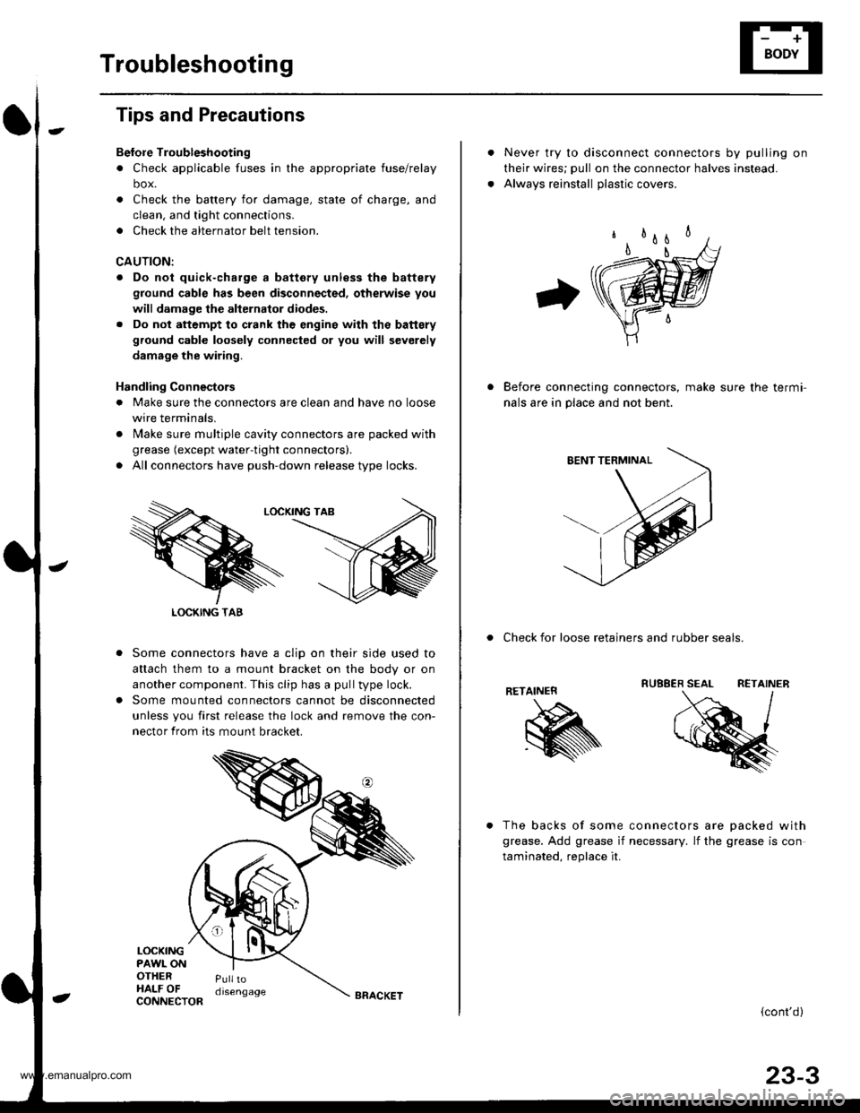
. All connectors have push-down release type locks.
Some connectors have a clip on their side used to
attach them to a mount bracket on the body or on
another component. This clip has a pull type lock.
Some mounted connectors cannot be disconnected
unless you first release the lock and remove the con-
nector from its mount bracket.
LOCKINGPAWL ONOTHERHALF OFPulltodisengage
LOCKING TAB
CONNECTORBRACKET
Never try to disconnect connectors by pulling on
their wires; pull on the connector halves instead.
Alwavs reinstall olastic covers.
Before connecting connectors, make sure the termi-
nals are in place and not bent.
. Check for loose retainers and rubber seals.
RETAINER
The backs of some connectors are oacked with
grease. Add grease if necessary. lf the grease is con
taminated. reolace it.
{cont'd}
23-3
www.emanualpro.com