Page 121 of 1395

Timing Belt
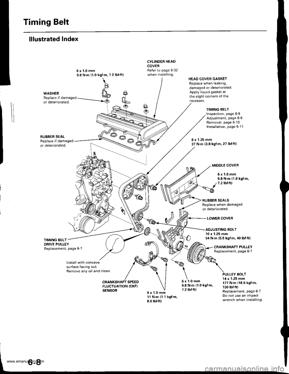
lllustrated Index
Cl
k6
CYLINDER HEADCOVERRefer to page 6-32when installing.
6x1.0mfi11 N.m {1.1 kgtm,8.0 rbtft)
HEAD COVER GASKETReplace when leaking,damaged or deteriorated.Apply liquid gasket atthe eight corners of theWASHERReplace if damagedor deteriorated,
RUEBER SEALReplace il damagedot detetiorated.
kgf.m,
\@
7.2 tbtft)
TIMING BELTInspection, page 6-9Adjustment, page 6-9Removal, page 6-10Installation, page 6-1 1
8 x 1.25 mm37 N.m (3.8 kst.m,27 lbf ftl
MIDOLE COVER
6x1.0mm9.8 N.m {1.0 kgf.m,1.2lbt.ftl
RUBBER SEALSReplace when damagedor deteriorated,
LOWER COVER
TIMING BELTORIVE PULLEYReplacement, page 6'7
ADJUSTING BOLT10 x 1.25 mm54 N.m (5.5 kgl.m, 40 lbf.ft)
CNANKSHAFT PULLEYneplacement, page 6-7
lnstall with concavesurface facing out,Remove any oal and clean,BOLT
CRANKSHAFT SPEEOFLUCTUATION ICKF}SENSOR
6x1.0mm9.8Nm(1.0kgl.m,7.2 tbl.ft)
14 x 1.25 mm177 N.m (18.0 kgf'm,130 tbf.fr)Replacement, Page 6-7Do not use an impactwrench when installing.
www.emanualpro.com
Page 122 of 1395

1.
2.
Inspection
Remove the cylinder head cover.
lnspect the timing belt for c.acks and oil or coolant
soaking. Replace the belt if it is oil or coolant
soaked. Remove any oil or solvent that gets on the
belt.
lnspect thisarea for wear.
After inspecting, retorque the crankshaft pulley bolt
to 177 N.m (18.0 kgnm, 130 lbf.ft).
Install the cylinder head cover (see page 6-32).
3.
Tension Adjustment
NOTE:
. Always adjust the timing belt tension with the engine
coto.
. Always rotate the crankshaft counterclockwise when
viewed from the pulley side. Rotating it clockwise
may result in improper adiustment of the belt ten-
sion.
'1. Remove the cylinder head cover
2. Set the No. 1 piston at TDC (see page.6-12).
3. Rotate the crankshaft five or six revolutions to set
the belt.
Set the No. 1 piston at TDC.
Loosen the adjusting bolt 1/2 turn (180') only.
4.
5.
ADJUSTING BOLT5,4 N.m (5.5 kgf.m,40 tbtftlFor adiustment only,
7.
8.
Rotate the crankshaft counterclockwise three teeth
on the camshaft pulley.
Tighten the adjusting bolt to the specified torque.
After adjusting, retorque the crankshaft pulley bolt to
177 N.m (18.0 kgf.m, 130 lbf.ft).
Installthe cylinder head cover (see page 6-32).9.
rotation,
6-9
www.emanualpro.com
Page 125 of 1395

Timing Belt
Installation (cont'd)
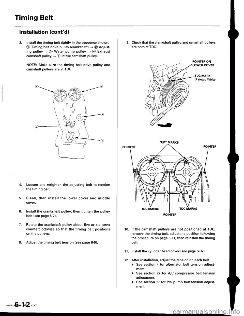
3. Install the timing belt tightly in the sequence shown.
O Timing belt drive pulley (crankshaft) J @ Adjust-
ing pulley =r @ Water pump pulley r @ Exhaust
camshaft pulley --) @ Intake camshaft pulley.
NOTE: Make sure the timing belt drive pulley and
camshaft pulleys are at TDC.
4. Loosen and retighten the adjusting bolt to tension
the timing belt.
5. Clean. then install the lower cover and middle
cover.
Install the crankshaft pulley, then tighten the pulley
bolt (see page 6-7).
Rotate the crankshaft pulley about five or six turns
counterclockwise so that the timing belt positions
on the pulleys.
Adjust the timing belt tension {see page 6-9).
1.
6-12
9. Check that the crankshaft pulley and camshaft pulleys
are both at TDC.
POINTER ON
lf the camshaft pulleys are not positioned at TDC,
remove the timing belt. adjust the position following
the procedure on page 6-11. then reinstall the timing
belt.
Installthe cylinder head cover (see page 6-32).
After installation, adjust the tension on each belt.
. See section 4 for alternator belt tension adjust-
menr.
. See section 22 for NC compressor belt tension
adjustment.
. See section 17 for P/S pump belt tension adjust-
ment.
10.
11.
12.
POINTER
www.emanualpro.com
Page 208 of 1395
DATA LINK CONNECTOR {DLC) I16P}Troubleshooting Procedures, page 1 1'60PRIMARY HEATED OXYGEN SENSOR
{PRIMARY HO2SI {SENSOR 1)Troubleshooling, page 11 110
SECONDARY HEATED OXYGENSENSOR{SECONDARY HO2S) {SENSOR 2)Troubleshooting, page 1 1-1 17
'97 - 98 models:
AIR CLEANERReplacement, page 1 1'194
Troubleshooting, page 1 'l -200
THROTTLE BODY (TB)Inspection, page 11 196Removal, page 11-197Disassembly, page 1 1-'198
POWERTRAIN CONTROL MODULE(PCM) (A/TI
Troubleshooting Procedures, page 1 1-60Troubleshooting. page 1 1'82
THROTTLE CABLEInspection/Adjustment, page 1 1-1 94Installation, page 11- 195
VENTILATION (PCV) VALVEInspection, page 1 1-201FAST IDLEVALVE (A/T}
(cont'd)
1 1-5
PGM-FIMAIN RELAYRelay Testing, page 11-l87Troubleshooting. page 1'1 188
SERVICE CHECK CONNECTOR {2PITroubleshooting Procedures, page 1 1-60
,a'=_-_
WAY CATALYTIC
Inspection, page 1 1-168
www.emanualpro.com
Page 209 of 1395
Component Locations
Index {cont'd)
39 - q, models:
THROTTLE BODY ITB)Inspection, page 1 1-196Removal, page 11- 197Disassembly, page 11 198THROTTLE CABLEInspectaon/Adjustment, page 1 1 194Installation, page I l'195
AIR CLEANERR€placomenl, page 1 1-194
CRANKCASEVENTILATION IFCVI VALVElnspection, page 11 201
FAST IDLE THERMO VALVE IA/T)Inspection, page 11'168
1 1-6
www.emanualpro.com
Page 266 of 1395

Troubleshooting
Troubleshooting Procedures (cont'dl
Symptom Chart
Listed below are symptoms and probable causes for problems that DO NOT cause the Malfunction Indicator Lamp (MlL) tocome on. lf the MIL was reported on, go to page 11-60.Troubleshoot each probable cause in the order listed (from left to right) until the symptom is eliminated,The probable cause and troubleshooting page reference can be found below.
Other Probable Causes for an engine that will not start:- Compression- Intake air leakage- Engine locked up- Timing belt- Starting system- Overheating- Battery
SYMPTOMPROBABLE CAUSE
Engine will not sta rt4, 2,3,5,20, 't5, 1
Hard starting2, 4, 12,17, 14, 't9
Cold fast idle too low7, a,9, 6, 17
Cold fast idle too high7,8,9,11,10
ldle speed fluctuates9,7,8, 't1, 10
Misfire or rough runningTroubleshoot for misfire on pages '11-126, 1|21LOl/\/ power2, 10,11, 13, '17, 18,20
Engine stalls2, 4, 12,1,20,9,5, 't6
Probable Cause List (For the DTC Ch8rt, see page ll-75.)
Probable CausePageSystem
Engine controt ruoaute (ecvtffi'I11-42
I 1-178Fuel oressure
PGM-Fl main relav
lgnition system
Crankshatt Position/Top Dead Center/Cylinder position sensor circuit
Intake Air Temperature (lAT) sensor ctrculr
ldle Air Control (lAC) Vatve
Fast idle thermo valve
ldle speed adjustment
Throttle body
Throftle cable
Manifold Absolute P."""rr"ffi
Throftle Position (TP) sensor
Barometric pressur" (gnno-
Ay'T gear position signal
Brake switch signal
Air Cleaner
Three Way Catalytic Converter (TWC)
Evaporative emission (EVAP) control
Contaminated fuel
1 1- 187
Section 4
5't1-'t31,146
6I '�t-95
711-152
81'l-168
1 1- 169
1011-196'1111-'194
12'1 'l -90
1 1- 103
1411-137
15Section 14
161 1- 166
17r 1-194
181 1,199'1911-203
20
11-64
www.emanualpro.com
Page 428 of 1395
Clutch
Speciaf Tools ....,..... ..........' 12-2
lllustrated lndex ........... .'." 12'3
Clutch Pedal
Adjustment ........."."."".12-4
Clutch Master Cylinder
RemovaUlnstallation '." 12'5
Slave Cylinder
Removal/lnstallation .'.. 12-6
Pressure Plate
RemovaUlnspection ..'." 12-7
Clutch Disc
Removal/lnspection ."'.. 12-8
Flywheel
Inspection ...................... 12-9
Replacement ....................................... 1 2-9
Clutch Disc, Pressure Plate
lnstallation ....................' 12-10
Release Bearing
Removal/lnspection ...... 12'11
lnstaflation ..................... 12-12
www.emanualpro.com
Page 430 of 1395

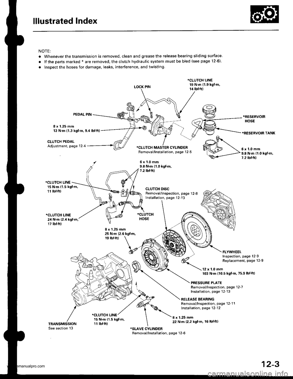
lllustrated Index
NOTE:
. Whenever the transmission is removed, clean and grease the release bearing sliding surface
.lfthepansmarked*areremoved,theclutchhydraulicsystemmustbebled(seepage1\
2-6).
. Inspect the hoses for damage. leaks. interference, and twisting.
LOCK PIN
*CLUTCH LINE19 N.m (1.9 kgj.m,14 tbtft)
8 x 1.25 mm13 N.m {1.3 kgf m,9.4lbtft)
PEDAL PIN.RESEFVOIR
HOSE
*RESERVOIR TANK
CLUTCH PEDALAdjustment, page 12-4*CI-UTCH MASTER CYLINDERFemoval/lnstallation, page 12-5
6x1.0mm9.8 N.m (1.0 kgf.m,7.2 tbf.ft)
*CLUTCH LINE15 N.m (1.5 kgt m,11 tbr.ft)
*CLUTCH LINE24 N.m {2.4 kgf.m,17 tbf.ft)
CLUTCH DISCRemoval/lnspection, page 1 2-8Installation, page 12,13
8 x 1.25 mm25 N.m {2.6 kgt m,19 rbf.ftt
I x 1.25 mm22 N.m 12.2 kgl'm, 16lbfft)
.o-.9r
WM\,".0--
ffi-P"8Nmlloks{m'
FLYWHEELInspection, page 12IRepiacement, page 12-9
12 x 1.0 mm103 N.m (10.5 kgtm,75.9 lbf ftl
PRESSURE PLATERemoval/lnspection, page'12-7
Installation, page'12 13
RELEASE BEARINGRemoval/lnspection, page 12-1'!Installation, page 12-12
*CLUTCH LINE15 N.m (1.5 kgt m,11 tbf.ft)
12-3
www.emanualpro.com