Page 95 of 1395
Actuator Disassembly
ACTUATOR ERACKET
VALVESTest, page 4-44
VACUUMTANK
)rd'
!
l
l
ACTUATOR CABLE
4-45
www.emanualpro.com
Page 100 of 1395
Engine Removal/lnstallation
Removal (cont'dl
Remove the cruise control actuator (see section 4).
Remove the mounting bolt and lock bolt, then
remove the P/S pump belt and pump.
10.
1t.
MOUNNNG BOLT8 x 1.25 mm2a N.m 12.4 kg{.m, 17 lbtftlP/S PUMPBELT
LOCK BOLTI x 1.25 mm24 N.m {2.4 kgtm, '17 lbf.ftl
12.Loosen the idler pulley bracket bolt and adjusting
bolt, then remove the air conditioning (A,/C) com-
pressor belt.
ID1TR PULI.f,Y ARACKET BOLT10 r 1.25 mma{ N.m 14.5lgtm,33 lbf.ft)
ADJUSTING BOLTLOCKNUT8 x 1.25 mm24 N.m {2.4 kgf.m, 17 lbf.ftl
5-4
13. Relieve fuel pressure {see section 11).
@ Do not 3mok6 whil€ working on th6
tugl systsm. Koep open flam€ or spark away from
the work area. Drain fuel only inlo an approved
container.
14. Remove the evaporative emission (EVAP) control
canister hose and tuel feed hose.
33 N.m (3.4 kgt.m,2s tbf.ft)
,%l
*ryft'fltr
\'t,f
EVAP CCCANISTER HOSE
www.emanualpro.com
Page 123 of 1395

Timing Belt
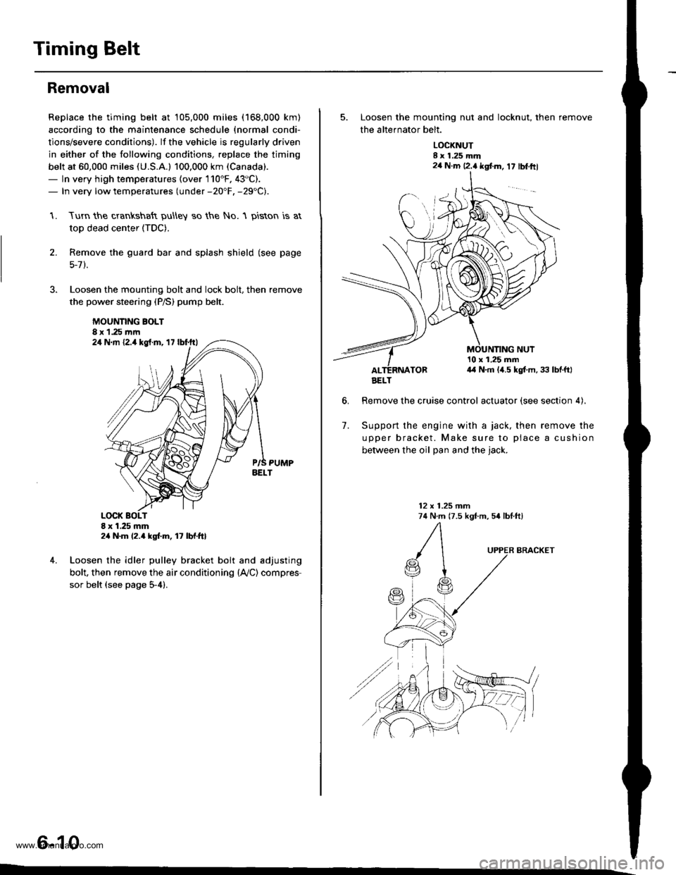
Removal
Replace the timing belt at 105,000 miles (168,000 km)
according to the maintenance schedule {normal condi-
tions/severe conditions). lf the vehicle is regularly driven
in either of the following conditions, replace the timing
belt at 60,000 miles (U.S.A.l 100.000 km (Canada).
- ln very high temperatures (over 110'F, 43"C).- In very low temperatures (under -20"F. -29"C).
Turn the crankshaft pu\ley so the No. 1 piston is at
top dead center (TDC).
Remove the guard bar and splash shield (see page
5-7 ).
Loosen the mounting bolt and lock bolt. then remove
the power steering (P/S) pump belt.
MOUNNNG BOLT8 x 1.25 rnm
1.
2.
,l
4. Loosen the idler pulley bracket bolt and adjusting
bolt, then remove the air conditioning (lVC) compres
sor belt (see page 5-4).
6-10
24 N.m {2.4 kgt.m, 17 lbf.ftl
24 N.m 12.4 kgf.m, lt lbf.ftl
5. Loosen the mounting nut and locknut, then remove
the altefnator belt.
LOCKNUTI x 1.25 mm2a N.m 12.4 kgt m, 17 lblftl
6.
10 x 1,25 mm4,1 N.m (,1.5 kgt m, 33 lbtftl
Remove the cruise control actuator (see section 4).
Support the engine with a jack, then remove the
upper bracket. Make sure to place a cushion
between the oil Dan and the iack.
12 x 1.25 mm74 N.m (7.5 kgf m, 54 lbtftl
7.
BRACKET
AELT
www.emanualpro.com
Page 132 of 1395

13. Remove the upper radiator hose, heater hose and
water bypass hose.
WATER BYPASS
UPPEBRADIATORHOSE
17
HEATERHOSE
Remove the engine wire harness connectors and
wire harness clamps from the cylinder head and the
intake manifold.
o Four fuel injector connectors
. Engine coolant temperature (ECT) sensor con-
neclor
. Radiator fan switch connector
. Coolant temperature gauge sendlng unlt connec-
tor
. Throttle position sensor connector
. Manifold absolute pressure {MAP) sensor con-
nector
Primary heated oxygen sensor (primary HO2S)
connector
ldle air control (lAC) valve connector
Distributor connector
Remove the spark plug caps and distributor from the
cylinder head.
Remove the cruise control actuator (see section 4).
Support the engine with a jack, then remove the
upper bracket. Make sure to place a cushion
between the oil pan and the iack (see page 6-10).
a
18. Remove the cylinder head cover.
19. Inspect the timing belt (see page 6-9).
CYLINDER
(cont'd)
6-19
www.emanualpro.com
Page 987 of 1395
Doors
Component
Tailgate Door:
NOTE: Refer to the
Location Index (cont'dl
1997 Series Honda CR-V Body Repair Manual {P/N 61S1030) for tailgate door removal.
LICENSE PLATETRIMReplacement, page 20-16TAILGATE OOORPosition Adjustment, page 20-23
TAILGATE DOORWEATHERSTRIP
HINGECOVER \
V
illt
REAR HATCH GLASS LATCHReplacement, page 20 18
HINGE
\
I
SUPPORT STRUT
€\A
LATCH STOPReplacement, page 20-17
Replacement,page 20'19
TAILGATE DOOR PANELRemoval and Installation, page 20-15
TAILGATE DOOR LATCHReplacement, page 20-17
TAILGATE DOORHANDLEReplacement, page 20-16
TAILGATE DOORSTRIKERAdjustment, page 20-25
k@/
%
-6
\
TAILGATE DOOR WEDGEAdiustment, page 20-25
N
REAR HATCH GLASSACTUATORReplacement, page 20-19
REAR HATCH GLASS
lVr
d+-BA^cKEr
d
d\
FLEXIBLE CARGOHOOK
20-6
www.emanualpro.com
Page 1000 of 1395

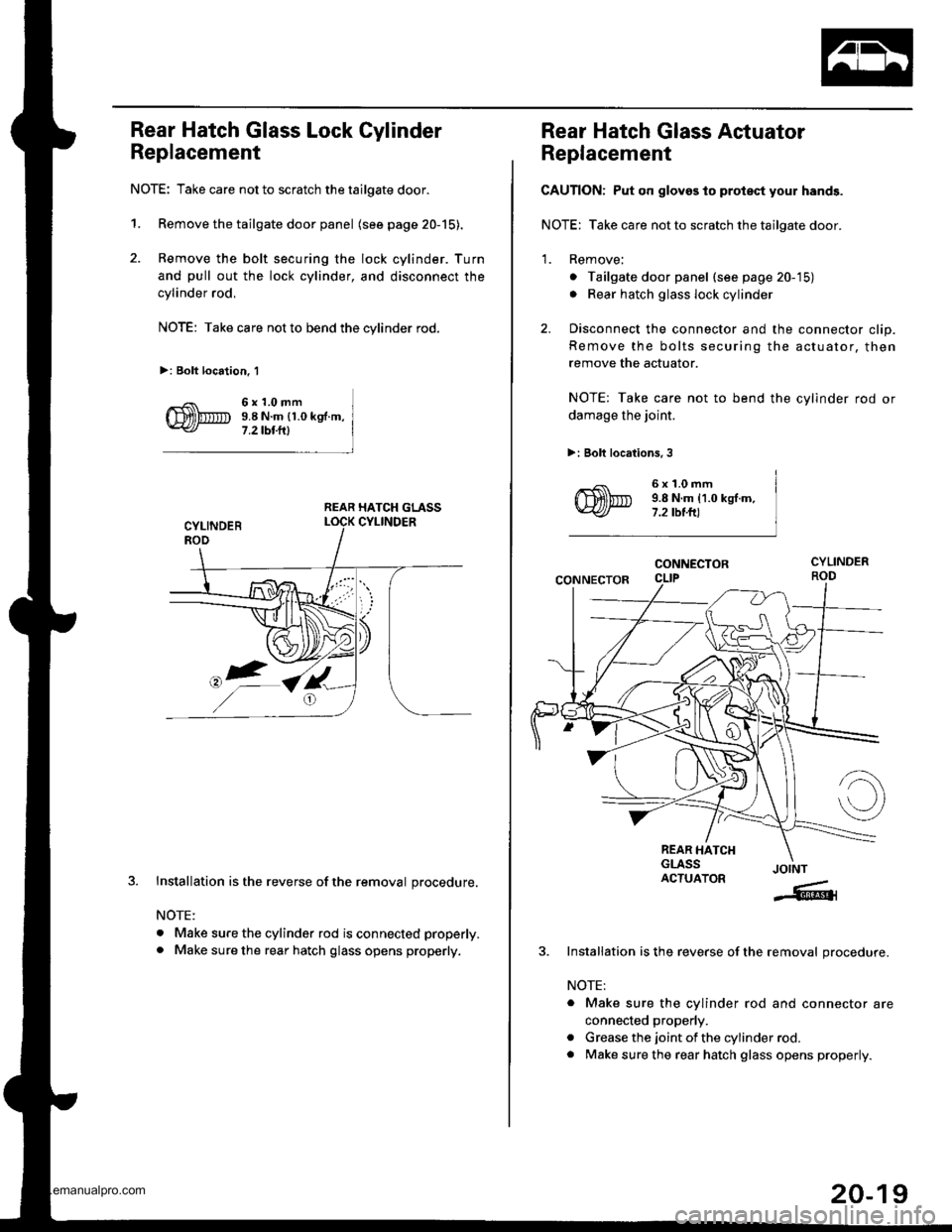
Rear Hatch Glass Lock Cylinder
Replacement
NOTE: Take care not to scratch the tailgate door.
1. Remove the tailgate door panel (see page 20-15).
2. Remove the bolt securing the lock cylinder. Turn
and pull out the lock cylinder, and disconnect the
cylinder rod,
NOTE: Take care not to bend the cylinder rod.
>: Bolt location. 1
6x1.0mm9.8 N.m {1.0 kg .m,
7 .2 tbt.lll
REAR HATCH GLASS
J.Installation is the reverse of the removal procedure.
NOTE:
. Make sure the cylinder rod is connected properly.
. Make sure the rear hatch glass opens properly.
Rear Hatch Glass Actuator
Replacement
CAUTION: Put on gloves to protsct your hands.
NOTE: Take care not to scratch the tailgate door.
1. Remove;
o Tailgate door panel (see page 20-'15)
. Rear hatch glass lock cylinder
2. Disconnect the connector and the connector clip.
Remove the bolts securing the actuator, then
remove the actuator.
NOTE: Take care not to bend the cylinder rod or
damage the joint.
>: Bolt locations, 3
6x1.0mm9.8 N.m 11.0 kgt.m,7.2 tbt.ft)
CONNECTOR
CONNECTOR
REAR HATCHGLASSACTUATORJOINT
-6{
Installation is the reverse of the removal procedure.
NOTE:
. Make sure the cylinder rod and connector are
connected properly.
. Grease the joint of the cylinder rod.
. Make sure the rear hatch glass opens properly.
20-19
www.emanualpro.com
Page 1008 of 1395
Power Mirror Replacement
NOTE: Tako care not to scratch the mirror, mirror mount
cover and door.
1. Lower the door glass fully.
2. Carefully pry out the mirror mount cover by hand,
,l
Disconnect the connector. then remove the mirror
mounting bolts while supponing the mirror,
>: Boh locations, 3
Installation is the reverse of the removal procedure,
NOTE: Make sure the connector is connected prop-
efly.
HOOK
MIRROR
Power Mirror Holder Replacement
CAUTION: Put on glovss to protest you. hands.
NOTE: Take care not to scratch the mirror.
1, Carefully pull out the bottom edge of the mirror
holder bv hand.
Separate the mirror holder from the actuator bv
slowly pulling them apart.
Reattach the hooks of the mirror holder to the actu-
ator, then Dosition the mirror holder on the actua-
tor. Carefully push the clip portions of the mirror
holder untilthe mirror holder locks into place.
Check the actuator ooeration.
ADHESIVE
20-27
www.emanualpro.com
Page 1176 of 1395

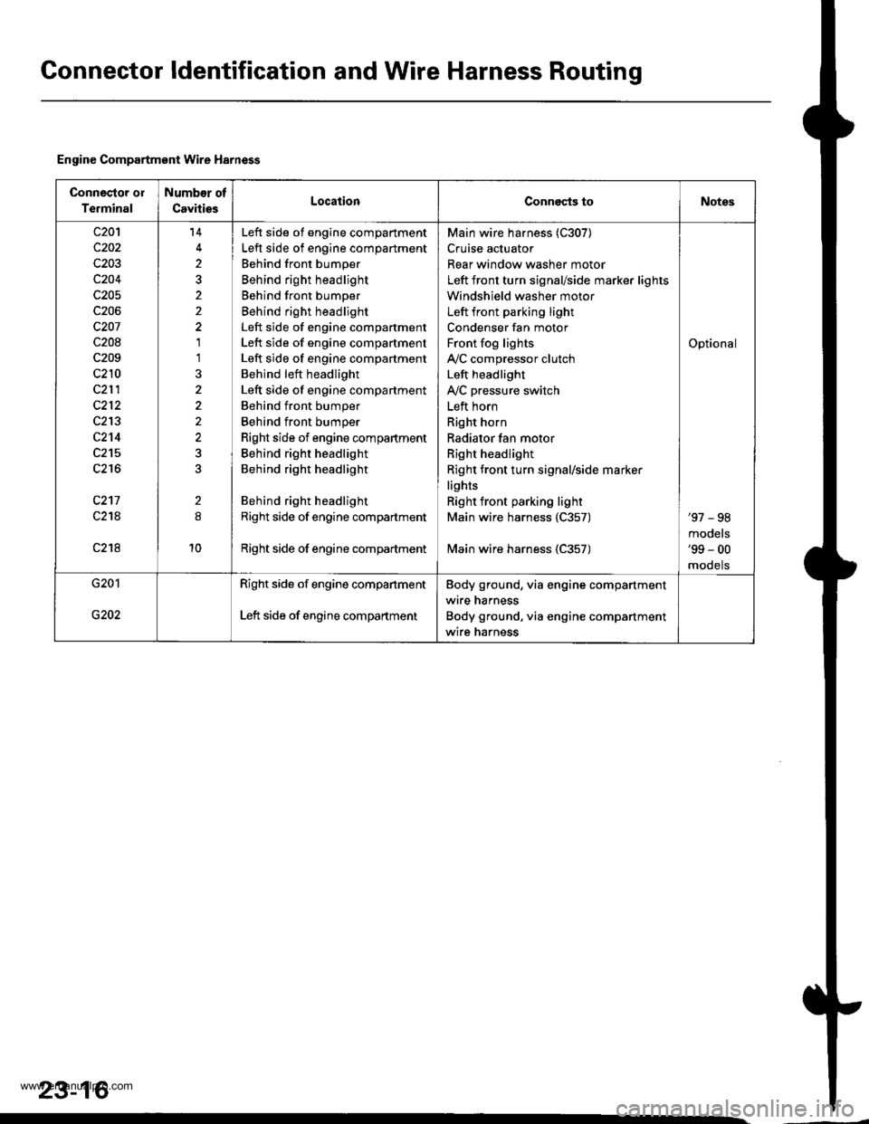
Gonnector ldentification and Wire Harness Routing
Engine Compartment Wire Harness
Connector ol
Terminal
Number of
CavitiesLocationConnects toNotes
c20'l
c202
c203
c204
c205
c206
c207
c208
c209
c210
c212
c213
c2't4
c215
c216
c217
c21A
c218
14
2
2
1'l
2
10
Left side of engine compartment
Left side of engine compartment
Behind front bumper
Behind right headlight
Behind front bumper
Behind right headlight
Left side of engine compartment
Left side of engine compartment
Left side of engine compartment
Behind left headlight
Left side of engine compartment
Behind front bumper
Behind front bumper
Right side of engine compartment
Behind right headlight
Behind right headlight
Behind right headlight
Right side of engine compartment
Right side of engine compadment
Main wire harness (C307)
Cruise actuator
Rear window washer motor
Left front turn signal/side marker lights
Windshield washer motor
Left front parking light
Condenser fan motor
Front fog lights
IVC compressor clutch
Left headlight
IVC pressure switch
Left horn
Right horn
Radiator fan motor
Right headlight
Right front turn signal/side marker
lights
Right front parking light
Main wire harness 1C357)
Main wire harness (C357)
Optional
'97 - 98
models'99 - 00
mooets
G201
G202
Right side of engine companment
Left side of engine compartment
Body ground, via engine compartment
wire harness
Body ground, via engine compartment
wire harness
23-16
www.emanualpro.com