1999 HONDA CR-V Starter
[x] Cancel search: StarterPage 62 of 1395

Starting System
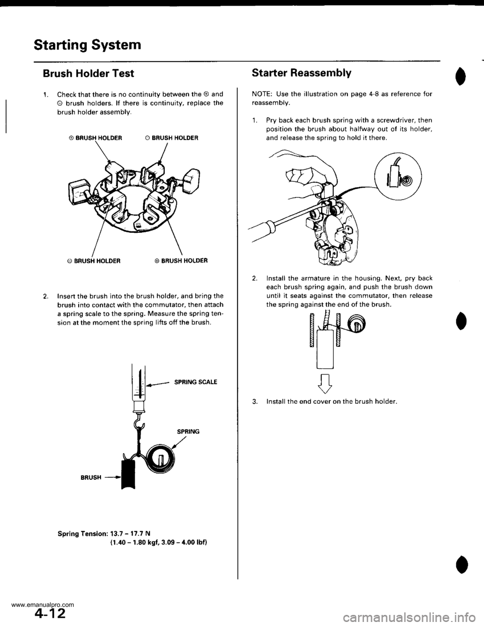
Brush Holder Test
1. Check that there is no continuity between the O and
O brush holders. lf there is continuitv, replace the
brush holder assembly.
O BRUSH HOLDER@ BRUSH HOLDER
Insert the brush into the brush holder, and bring the
brush into contact with the commutator, then attach
a spring scale to the spring. Measure the spring ten-
sion at the moment the spring lifts off the brush.
SPRING SCALE
Spring Tension: 13.7 - 17.7 N
(1.40 - 1.80 kgf, 3.09 - 4.00 lbf)
4-12
Starter Reassembly
NOTE: Use the illustration on page 4I as reference for
reassemDty.
1. Pry back each brush spring with a screwdriver, then
position the brush about halfway out ol its holder,
and release the spring to hold it there.
2. Install the armature in the housing. Next, pry back
each brush spring again, and push the brush down
until it seats against the commutator, then release
the spring against the end of the brush.
- E^
F*4#-@
6t taal la
tlll
3. Install the endon the brush holder.
ft
cover
www.emanualpro.com
Page 63 of 1395

,r1.?
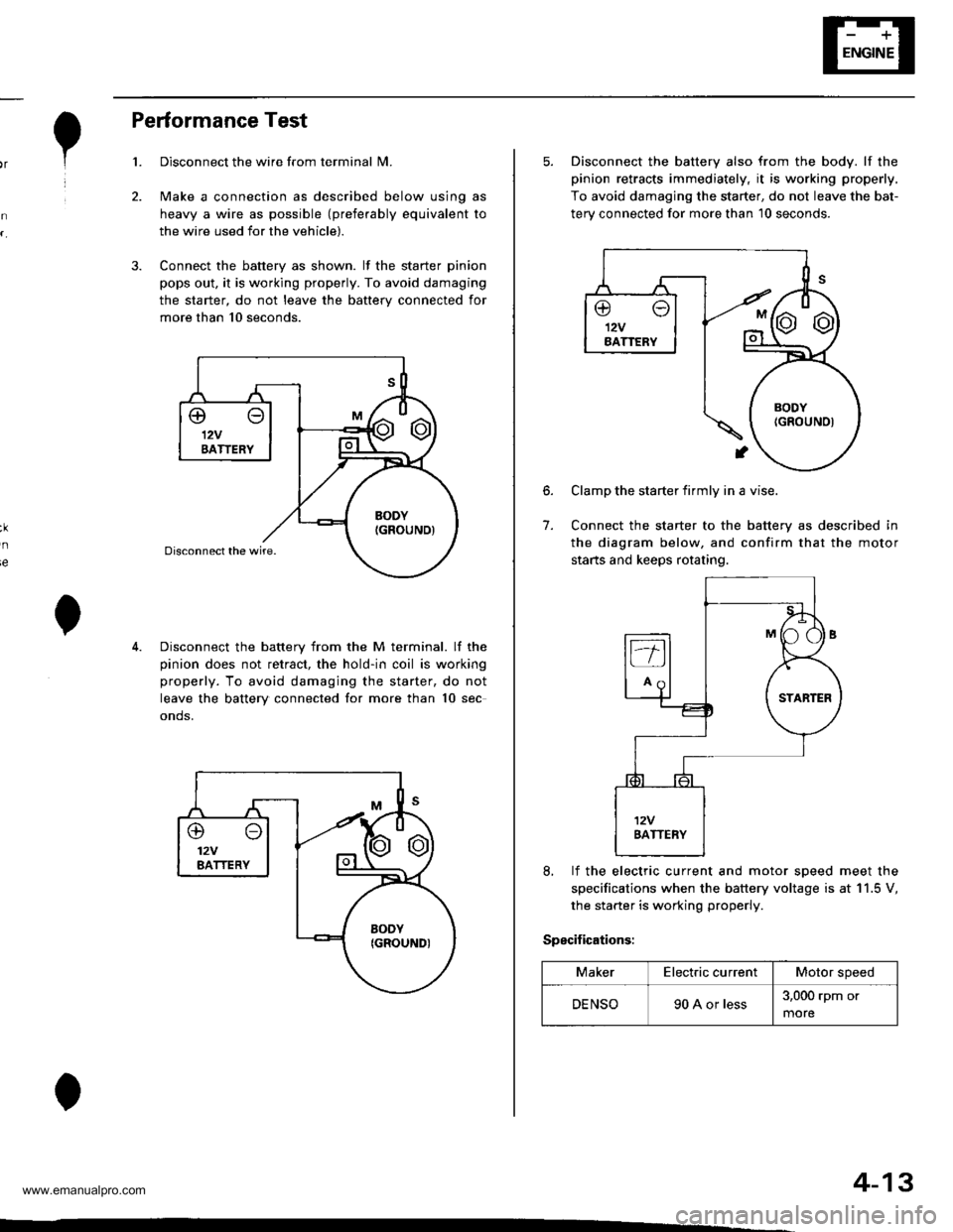
Performance Test
Disconnect the wire from terminal N4.
Make a connection as described below using as
heavy a wire as possible (preferably equivalent to
the wire used for the vehicle).
Connect the battery as shown. lf the starter pinion
pops out. it is working properly. To avoid damaging
the starter, do not leave the battery connected for
more than 10 seconds.
3.
ie
Disconnect the battery from the M terminal. lf the
pinion does not retract, the hold-in coil is working
properly. To avoid damaging the starter, do not
leave the battery connected for more than 10 sec
onds.
@o12VBATTERY
4-13
5. Disconnect the battery also from the body. lf the
pinion retracts immediately, it is working properly,
To avoid damaging the starter, do not leave the bat-
terv connected for more than 10 seconds.
6.
7.
Clamp the starter firmly in a vise.
Connect the starter to the battery as described in
the diagram below, and confirm that the motor
starts and keeps rotating.
8, lf the electric current and motor soeed meet the
specifications when the battery voltage is at 11.5 V,
the starter is working properly.
Specifications:
MakerElectric currentMotor speed
DENSO90 A or less3,000 rpm or
more
www.emanualpro.com
Page 112 of 1395

Engine Removal/lnstallo cton
Installation (cont'd)
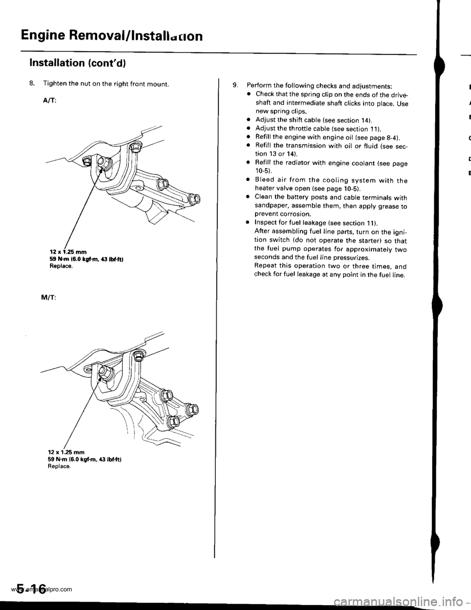
8. Tighten the nut on the right front mount.
AlTi
59 .m 16.0 tgt m, (l lbfftlReplace.
MlTi
12 x'1.25 mm59 N.m 16,0 kgt m, /(} lbt ttlReolace.
5-16
9. Perform the following checks and adjustments:. Check that the spring clip on the ends of the drive-shaft and intermediate shaft clicks into place. Usenew spring clips.. Adjust the shift cable (see section l4).. Adjust the throttle cable (see section 11).. Refill the engine with engine oil (see page g-4).
. Refill the transmission with oil or fluid (see sec-tion 13 or 14).
. Refill the radiator with engine coolant (see page
10_5).
. Bleed air from the cooling system with theheater valve open (see page l0-5).. Clean the battery posts and cable terminals withsandpaper, assemble them, then apply grease toDrevent corrosron.. Inspect for fuel leakage (see section 1l).After assembling fuel line pans, turn on the igni-tion switch (do not operate the starter) so thatthe fuel pump operates for approximately twoseconds and the fuel Iine pressurizes.
Repeat this operation two or three times, andcheck for fuel leakage at any point in the fuel line.
www.emanualpro.com
Page 204 of 1395

Fuel and Emissions
Special Tools ...................... 11-2
Component Locations
lndex ...................... ....,.... 11-3
Svstem Description
Vacuum Connections ...........,....,.,................. 1 1-9
Electrical Connections ................................... 1 1-15
System Connectors .,.,,.,............................,.,. 1 1-36
Troubleshooting
Troubleshooting Procedures,.,..................... 11-60
Engine Control Module/Powertrain ConttolModule Terminal Arrangement .............., 11-67
Diagnostic Trouble Code Chart .................... 1 t-75
How to Read Flowcharts .......,.....,.,............... I 1-79
PGM-Fl System
System Description .................,.,.,,,............... 1 1-80
Troubleshooting Flowcharts
Engine Control Module/PowertrainControl Module ........11-52
Manifold Absolute Pressure Sensor ............. 11-90
Intake Air Temperature Sensor .................... 1 1-95
Engine Coolant Temperature Sensor .,..,.,.... 1 1-99
Throttle Position Sensor ...........,.....,.,.,..,...... I 1'103
Primary Heated Orygen Sensor (Sensor 1) ... 11-110
Secondary Heated Oxygen Sensor{Sensor 2l .................. 1 1-117
Heated Oxygen Sensor Heater ..................... 11-121
Fuef Supply System ......11-124
Random Misfire ,....,.,..... 11-126
Mistire Detected in One Cylinder .....-........... 11-128
Knock Sensor ................ 11-130
CKP/TDC/CYP Sensor .................................... 1 1-131
Vehicle Speed Sensor ...............................,.... 1 1-135
Barometric Pressure Sensor .....,...,...,.,,........ 1 1-137
Electrical Load Detector ...,.,.......................... 1 1-138
CKF Sensor ................,.,, '11-112
ECM/PCM lnternaf Circuit ............................. 11'117
HO2S Replacement .,.,.,. 11-148
ldle Control System
System Description ............ 11-149
Troubleshooting Flowcharts
ldle Control System ...... 11-150
fdle Air Control Valve ......................,............. 11-152
Air Conditioning Signal ................................. I 1-155
Alternator FR Signal ...................................... 1 1-159
Starter Switch Si9na1 .................................... t l-161
Power Steering Pressure Switch Signal ...... 11-162
Brake Switch Si9na1 ...................................... 11-166
Fast ldle Thermo Valve .,.,.............................,.,.,. 11-168
ldle speed setting .............. 11-169
Fuel Supply System
Fuel Lines ............................ 11-171
Fuef Tube/Ouick-Conneci Fittings ..................... 11 -175
System Description ............ 11-178
Fuel Pressurg ...................... 11-178
Fuel Iniectors ................,..... 11-179
Fuel Pressure Re9u1ator .............................,.,...., f 1-181
Fuef Fifter ....,.,.,.,,,,.,............11-142
Fuel Pump ........................... 11-183
Fuel Gauge .......................... 11-184
Fuel Gauge Sending Unit ................................... I 1-185
Low Fuel Indicator System ...........,.,..,............... 1 1-185
PGM-FI Main Relay ............. 11-187
Fue|Tank................ ............. 11-191
Intake Air System
System Description ............ 11-193
Air Cleanel ,.,.,..................... 11-194
Throttle Cable ..................... 11-194
Throttle Body........ .............. 11-196
Emission Control System
System D$cription ...,....,.,. 11-199
Tailpipe Emission ............... 11-199
Three Way Catalytic Converter ..................,.,...,, 11-199
Positive Crankcase Ventilation System .,.,,,,.,.., 11-2O1
Evaporative Emission Controls .........,.,.,............ 11-203
www.emanualpro.com
Page 271 of 1395

PCM CONNECTOR C (31PI
ferminalnumberWirecolorTerminalnameDoscriptionSignal
'tBLUiREDCKFP (CKF SENSOR PSIDE)Detects CKF sensor.With engine running: pulses
2BLUCKPP (CKP SENSOR PSIDE)Detects CKP sensor.With engine running: pulses
3GRNTDCP (TDC SENSOR PSIDE)Detects TDC sensor.With engine running: pulses
4YELCYPP (CYP SENSOR PSIDE)Detects cYP sensor.With engine running: pulses
5BLU,frEDACS (A/C SWTTCHSIGNAL)Detects A,/C switch signal.With AJC switch ON: 0 VWith A,/C switch OFF: battery voltage
BLU/ORNSTS (STARTER SWITCHSIGNAL)
Detects starter switch signal.With starter switch ON (lll): bafteryvoltageWith staner switch OFF: 0 V
7BRNSCS (SERVICE CHECKSIGNAL)
Detects service check connectorsignal (the signal causing a DTCindication)
With the connector connected: 0 V
With the connector disconnected: about
5 V or battery voltage
8LT BLUK-LINESends and receives scan toolsrgnal.With ignition switch ON (ll): pulses
10WHT/BLUVBUUP)
(VOLTAGE BACKPower source tor the PCMcontrol circuit. Power source for
the DTC memory
Battery voltage at all times
11WHT/REDCKFM (CKF SENSOR MSIDE)Ground for CKF sensor signal.
12WHTCKPM (CKP SENSOR I\4SIDE)Ground lor CKP sensor signal.
13REDTDCM (TDC SENSOR MSIDE}Ground for TDC sensor signal.
14BLKCYPM (CKP SENSOR MSIDE}Ground for CYP sensor signal.
16GRN
PSPSW (P/S PRESSUREswtTcH)Detects PSP switch signal.At idle with steering wheel in straightahead position:0 VAt idle with steering wheel at full lock:
battery voltage
17WHT/REDALTF (ALTERNATOR FRSIGNAL)
Detects alternator FR signal.With fully warmed up engine running:
0 V-battery voltage {depending onelectrical load)
18BLUA/VHTVSS (VEHICLE SPEEDSENSOR)Detects VSS signal.Wirh ignition switch ON (ll) and frontwheels rotating: cycles 0 V - 5 V or bat-tery voltage
Wire side of femaie terminalsPCM CONNECTOR C {31PINOTE: Standard battery voltage is 12 V.
(cont'd)
www.emanualpro.com
Page 273 of 1395

Engine/Powertrain Control Module Terminal Arrangement - 38 - 00 Models
ECM/PCM CONNECTOR A (32P}
,/./5aIsca
,/ l,/t5ItsTs
n2ls!uCI
Wire side ot female terminalsECM/FCM CONNECTOR A {32P)NOTE: Standard baftery voltage is '12 V.
D93criptionSignal
3BLU2WBS {EVAP BYPASSSOLENOID VALVE)Drives EVAP bvoass solonoid valve.With ignirion switch ON {ll)r battery voltage
LT GRNMHTVSV {EVAP CONTROL CANISTEB VENT SHUT VALVE)D.ives EVAP controlcanisler vent shutWith ig^ition switch ON (ll): battery voltage
5',BLUCRS (CRUISE CONTROL SIG'NAL)Shift Oown signalinputfrcm cruise conWhen cruise control is used: pulses
6RED/YEL
PCS (EVAP PURGE CONTROLSOLENOID VALVE)Drives EVAP purge controlsolonoid valve.With engins running, engine coolant, below 154'F(68'C)r battery voltageWith engine running, engine coolant, above 154"F{6a'C}r duty conl.olled
8ELIOWHTSO2SHTC (SECONDARVHEATED OXYGEN SENSORHEATER CONTROL)
Drives sacondary heated oxygen sensorWith ignition switch ON (ll): banery voltageWith fully warmed up engine running: duty
10BRNSCS (SERVICE CHECX SIGNAL)Detects seNics check conneclor signal(he signalcausing a DTC indicatjon)with rhe lerminal connected:0 vWith the rerminaldisconnectedrabout 5 v or
l4'rGRN/8LKD4IND (D4INDICATOR)+3DIND (D INDICATORTIDrives D4*3. Dr'indicaior light.W,rh 04' , O" indrcator light turned O batter,
With D4*3, D*. indicator light turned OFFr0 V
16GRNI/ELFLR (FUEL PUMP RELAY)Drivss fusl pump relay.0 V for iwo seconds after ru'nin9 ign'lion swilchON lll), then banery voltage
17AL|(/REDACC (I/C CLUTCH RELAY}Drives l,/C clurch rclay.With compressor ONr0 VWith compressor OFF: battery voltage
18GRN/ORNMIL (MALFUNCTION INDICA.TOR LIGHT)Driv€s MlL.With MlLturned ON:0 VWith MIL turned OFF: battery voltage
19BLUNEP (ENGINE SPEED PULSE)Outputs engine spsed pulse.With sngine runnin9: pulses
20GRNFANC {RADIATOR FAN CONTROL)Drives r6diator fan rslay.With radaator fan running:0 VWith radaatorfan stopped: battery vollage
218LU/t/ELK-LINESends and receiv€s scan toolsignal.With ignition switch ON (ll): p'rlses
23WHT/REDSHO2S (SECONDARY HEATEDOXYGEN SENSOR. SENSOR 2iDetects secondary h€at€d oxygen sensorWith throttle fully opened from idle wilh fullywalmed up engine: above 0.6 Vwith rhrottle quickly closed: below 0-4 V
21BLU/WHTSTS (STARTER SWITCH SIG,NAL}Dotocts srarter switch signal.Whh staner switch ON (lll): batlery voltageWith srarter switch OFF: 0 V
26GBNPSPSW {P/S PsESSUFESWITCH SIGNAL)Detecrs PSP switch signal.At idle with steeing wh€el in stBighl ahead position: 0 VAt idls with nee ng wheel al full lockr banory voltage
2fBLU/BEOACS (Ir'C SWTCH SIGNAL}D€tects ly'C switch signal.With Ay'C switch ON:0 VWith l/C swil€h OFF: about 5 V
2A'\WHT/NEDSLU {INTERLOCK CONTROLUNIT)Orives interlock control unil.With ignilion switch ON (ll)and brake pedaldepressed: battery vohage
29LT GRNPTANK (FUEL TANK PRES'SURE SENSOR)Detocts fueltank pressure sensor signal.With agnition switch ON (ll) and fuel fill capopensd; about 2.5 v
GBN/FEDEL (ELD}Detects ELD signal.Wirh paaing rightstumed on at idle:about 2.5 - 3.5 VWith low beam headlights tumed on at idle:about 1.5-2.5V
GRN/WHTBKSW (BRAKE SWTTCH)Dst€cts brake switch signal.Wirh brake pedal released:0 VWith brake pedal depressed: battery vollage
13: '98 modsl
15: USA(cont'd)
11-71
www.emanualpro.com
Page 282 of 1395

PGM-FI System
System Description
INPUTS
CKP/TDC/CYP Sensor
CKF Sensor
MAP Sensor
ECT Sensor
IAT Sensor
TP Sensor
Primary HO2S
Secondary H02S
vss
KS*5
BARO Sensor
ELD*6
Starter Signal
ALT FR Signal
Air Conditioning Signal
Ay'T Gear Position Signal*1
Baftery Voltage (lGN.1)
Brake Switch Signal
PSP Switch Signal
Fuel Tank Pressuae Sensor*4. *5
Countershaft Speed Sensor*1
Mainshaft Speed Sensor*r
OVER-DRIVE Switch Signal*s
ENGINE CONTROL MODULE (ECM)/
POWERTRAIN CONTROL MODULE (PCM) OUTPUTS
|iuel 1"j""- Th,rhg ""d Drrafr";-l
Et*-.nt"tdt"cont.orl
to,r*,c;;trffi;]
l.----.---:. .Lrgnrnon |lmrng Lonrror I
Ecir/PcM B*k',p Fr""il]
m;"t-ll-r*'io*l
Fuel Injectors
PGM-Fl Main Relay (Fuel Pump)
MIL
IAC Valve
Ay'C Compressor Clutch Relay
Radiator Fan Relay
Condenser Fan Relay
ALT
tcM
EVAP Purge Control Solenoid
Valve
Primary HO2S Heater
Secondary H02S HeaterEVAP Bypass Solenoid Valve*a *5
EVAP Control Canister Vent Shut
DLC
Lock-up Control Solenoid Valve*l
Shift Control Solenoid Valve*1
Ay'T Clutch Pressure Control
Solenoid Valve*1
D4 Indicator Light'1 *3, *a
D Indicator Light,l *5
OVER-DRIVE OFF Indicator
Lighl*t *:
*1: A/T {3:'97 model'2: M/f +4:'98 model*5: '99 - 00 models"6: USA
PGM-Fl System
The PGM-Fl system on this model is a sequential multiport fuel injection system.
Fuel iniecior Timing and Duration
The ECM/PCM contains memories for the basic discharge durations at various engine speeds and manifold pressure. The
basic discharge duration, after being read out from the memory, is further modified by signals sent from various sensors
to obtain the final discharge duration.
ldle Air Control
ldle Air Control Valve (lAC Valve)
When the engine is cold, the Ay'C compressor is on, the transmission is in gear, the brake pedal is depressed, the P/S load
is high, or the alternator is charging, the ECM/PCM controls current to the IAC Valve to maintain the correct idle speed.
lgnition Timing Control
o The ECM/PCM contains memories for basic ionition timing at various engine speeds and manifold air flow rates.
lgnition timing is also adjusted for engine coolant temperature.
. A knock control system was adopted which sets the ideal ig nition timing for the octane rating of the gasoline used.*s
Other Control Funstions
1. Starting Control
When the engine is started. the ECM/PCM provides a rich mixture by increasing fuel injector duration.
2. Fuel Pump Control
. When the ignition switch is initially turned on (ll). the ECMiPCM suppli€s ground to the PGM-FI main relay that
supplies current to the fuel pump for two seconds to pressurize the fuel system.
. When the engine is running, the ECM/PCM supplies ground to the PGM-FI main relay that supplies current to the
fuel oumo.
. When the engine is not running and the ignition is on, the ECM/PCM cuts ground to the PGM-FI main relay which
cuts current to the fuel pump.
1 1-80
www.emanualpro.com
Page 351 of 1395

ldle Control System
System Description
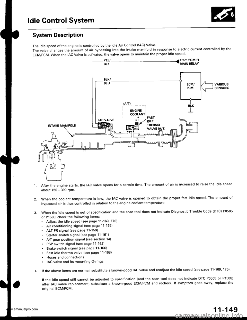
The idle speed of the engjne is controlled by the ldle Air Control (lAC) Valve'
The valve changes the amount of air bypassing into the intake manifold in response to electric current controlled by the
ECM/PCM. When the lAc valve is activated, the valve opens to maintain the proper idle speed.
YEL/ From PGM'FI
BLK TMAIN RELAY
VARIOUSSENSORS
4.
IAC VALVE
INTAKE MANIFOLD
After the engine starts, the IAC valve opens for a certain time. The amount of air is increased to raise the idle speed
about 150 - 300 rpm.
when the cootant temperature ts row, the lAc valve is opened to obtain the proper fast idle speed The amount o{
bvoassed air is thus controlled in relation to the engine coolant temperature
When the idle speed is out o{ specification and the scan tool does not indicate Diagnostic Trouble Code (DTC) P0505
or P1508, check the following items:
. Adjust the idle speed (see page 11-169, 170)
. Air conditioning signal (seepagell-1551
. ALT FR signal (see page 1l-159)
. Starter switch signal (see page 11-16'1)
. A,/T gear position signal (see section 14)
. PSP switch signal (seepagell-162)
. Brake switch signal (see page 11-165)
. Fast idlethermovalve (see page'11 168)
. Hoses and connecttons. IAC valve and its mounting O-rings
lf the above items are normat, suDslitute a known-good IAC valve and readjust the idle speed {see page 11-169, 170)
lf the idle speed still cannot be adjusted to specification (and the scan tool does not indicate DTC P0505 or Pl508)
after IAC valve reolacement, substitute a known-good ECM/PCM and recheck lf symptom goes away' replace the
original ECM/PCM.
11-149
www.emanualpro.com