1999 HONDA CR-V Set idle
[x] Cancel search: Set idlePage 343 of 1395

38 - 00 modeb:
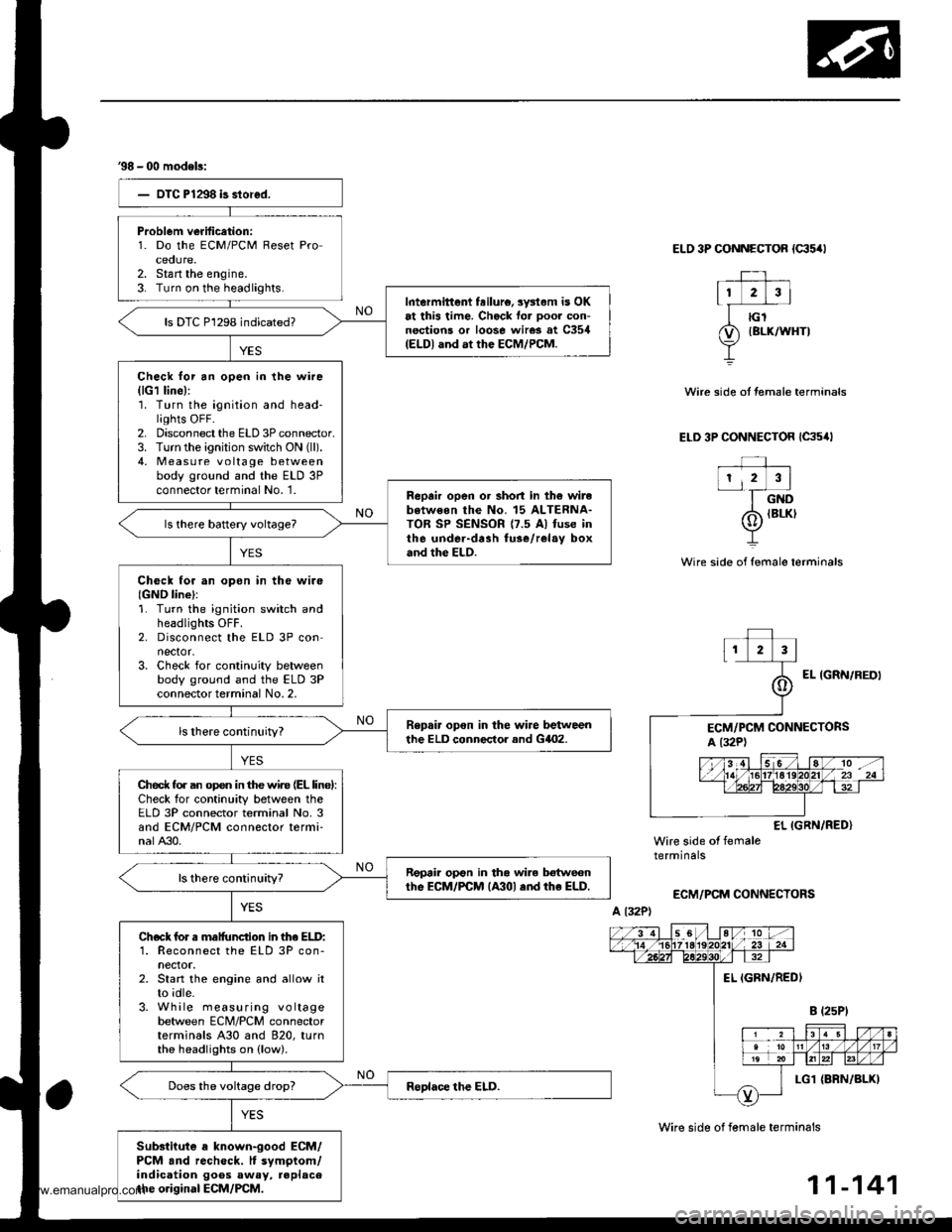
Problem verification:1. Do the ECM/PCM Reset Proceoure.2. Stan the engine.3- Turn on the headlights.Intermittent feilure, sysl.m is OKat this time. Check for ooor con-nections or loose wires at C354(ELDI and at the ECM/PCM.
ls DTC P1298 indicated?
Check lor an open in the wire(lG1 line):'1. Turn the ignition and head-lights OFF.2. Disconnect the ELD 3P connector.3. Turn the ignition switch ON (ll).
4, Measu re voltage betweenbody ground and the ELD 3Pconnector terminal No. '1.Reprir open or short in th6 wirebotweon the No. 15 ALTERNA-TOR SP SENSOR {7.5 Al fuse inthe under-drah fuse/relay boxand the ELD.
Check tor an opon in tho wire{GND line}:1. Turn the ignition switch andheadlights OFF.2. Disconnect the ELD 3P connector.3. Check for continuity betweenbody ground and the ELD 3Pconnector terminal No. 2,
Repair opon in the wire betweenthe ELD conneclor and GilO2.
Ched( fo. an op€n in the wir€ (EL linel:Check for continuity between theELD 3P connector terminal No. 3and ECM/PCM connector termi-nalA30.
Repair op€n in tha wile botwecnthe EcM/PCM lA30l .nd rhe ELD.
Check for s malfunction in lhe ELD:1. Reconnect the ELD 3P con-nector.2. Start the engine and allow itto idle.3. While measuring voltagebetween ECM/PCM connectorterminals A30 and 820, turnthe headlights on (low).
Substiiute a known-good ECM/PCM and recheck. It symptom/indication goos away, replacethe original ECM/PCM.
ELO 3P CONNECTOR {c35/rl
Wire side of female terminals
Wire side of female terminals
Wire side ot temale terminals
ELD 3P CONNECTOR {C35,lt
EL IGRN/RED}Wire side of femaletermrnars
ECM/PCM CONNECTORS
A l32P)
11-141
www.emanualpro.com
Page 354 of 1395

ldle Control System
ldle Air Control llAC) Valve
The scan tool indicates Diagnostic Trouble Code (DTC) Pl508: A probtem in the ldle Air Controt flAC) varvecircuit.
The IAC Valve changes the amount of air bypassing the throttle body in response to a current signal from the ECM/PCM inorder to maintain the proper idle speed.
37 model;
IAC VALVE 2P CONNECTOR {C132}
,f rcp'# IYEL/BI.(II2f-1-d)
Y
Wir€ side of female terminals
PCM CONNECTOR A I32PI
tacvIBLK/BLU)
From AIR To INTAKECLEANER MANIFOLD
Wire side of female terminals
The MIL has beon .eport€d on.OIC Pl508 is sto.ed.
Problem veiification:1. Do the PCM Reset Procedure.2. Start the engine, and warm itup to normal operating tem-perature.
Inte.mittent failure, systcm b OKat thi3 time. Check tor poo. con-nections or loose wircs at C132(lAC v.lvel and at the PCM.
ls DTC Pl508 indicated?
Check lor an open in the wir6{lGPl lins}:1. Turn the ignition switch OFF.2. Disconnect the IAC valve 2Pconnector.3. Turn the ignition switch ON {ll).4. Measure voltage between bodyground and the IAC valve 2Pconnector term inal No.2.
Repair open in the wire trctwoontha IAC v!lv6 and the PGM-Flmain relly.
Chock for an opan o. short in thowi.e (lACv linel:1. Turn the ignition switch OFFand reconnect the IAC valve2P connector.2. Disconnect the PCM conneclorA (32P).
3. Turn the ignition switch ON {ll).4, Measure voltage betweenbody ground and PCM con-nector terminal A12.
{To page 1l-153)
www.emanualpro.com
Page 371 of 1395

ldle Speed Setting
Inspoction/Adiustmont
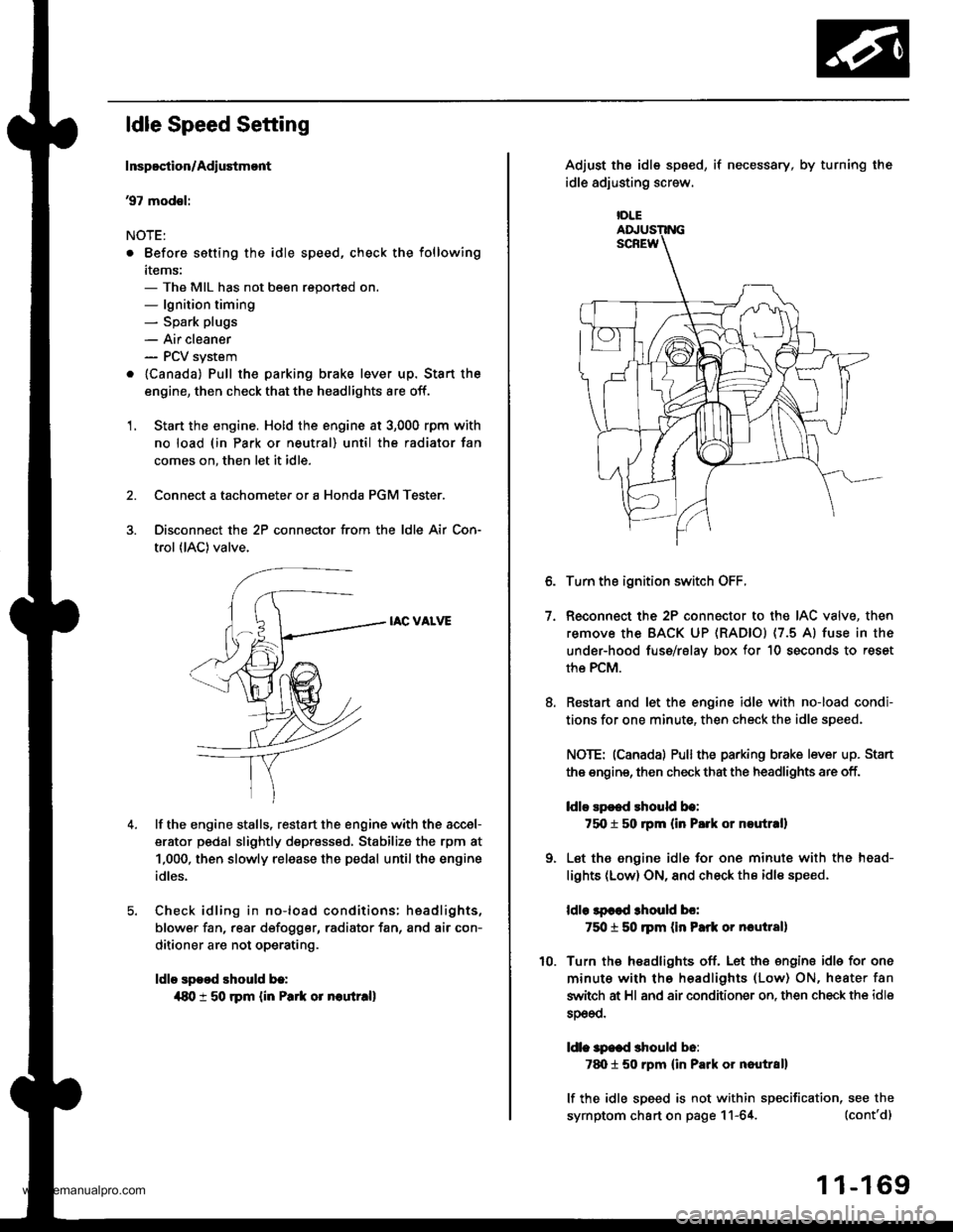
37 modsl:
NOTE:
. Before setting the idle speed, check the following
items:- The MIL has not been reportsd on.- lgnition timing- Spark plugs
- Air cleaner- PCV system
. lcanada) Pull the parking brake lever up. Stan the
engine, then check that the headlights are off.
1. Start the engine. Hold the engine at 3,000 rpm with
no load (in Park or neutral) until the radiator fan
comes on, then let it idle.
Connect a tachometer or a Honda PGM Tester.
Disconnect the 2P connector from the ldle Air Con-
trol (lAC) valve.
IAC VALVE
lf the engine stalls, restart the engine with the accel-
erator pedal slightly depr6ss6d, Stabilize the rpm at
1,000, then slowly release the pedal until the engine
idles.
Check idling in no-load conditions: hsadlights,
blower fan, rear d€fogger, radiator fan, and air con-
ditioner are not operating.
ldle spood should b.:
{80 t 50 rpm {in Park or noutr.ll
IDLE
7.
Adjust the idle sp6ed,
idle adjusting screw.
if necessary, by turning the
Turn the ignition switch OFF.
Reconnect the 2P connector to the IAC valve, then
remove the BACK UP (RAD|Ol (7.5 Al fuse in the
under-hood fuse/rslav box for 10 seconds to reset
the PCM.
Restart and let the engine idle with no-load condi-
tions for one minute, then check the idle speed.
NOTE: (Canadal Pullthe parking brake lever up. Stan
the engine, then check that the headlights are off.
ldlo Ep€ed rhould be:
75O t 50 rpm (in P.rk or noutr.ll
Let the engine idl6 for one minute with the head-
lights (Low) ON, and check th€ idl€ speed.
ldle lpcod 3hould bo:
750 t 50 ]pm (in Park or nautlal)
Turn the headlights off. Let th€ engine idle for one
minute with the headlights (Low) ON, heater fan
switch at Hl and air conditioner on. then check the idle
sDeeo.
ldl. specd should b6:
7d) 1 50 rpm {in Park or nautral}
lf the idle speed is not within specification, see the
symptom chart on page 11-64. (cont'd)
1 1-169
www.emanualpro.com
Page 372 of 1395

ldle Control System
ldle Speed Setting (cont'd)
38 - 0O mod6l3:
NOTE: Before setting the idle speed, check the follow-
ing items:- The MIL has not been reported on.- lgnition timing- Spark plugs
- Air cleaner- PCV system
1. Start the engine. Hold the engine at 3.000 rpm with
no load (in Park or neutral) until the radiator fan
comes on, then let it idle.
Connect a tachometer.
Disconnect the IAC valve 2P connector and the EVAP
purge control solenoid valve 2P connector.
CONTROLSOLENOID VALVE
SOLENOID VALVE
lf the engine stalls, restart the engine with the accel-
erato. pedal slightly depressed. Stabilize the rpm at
1,000, then slowly release the pedal until the engine
idles.
Che€k the idle in no-load conditions: headlights, blow-
er fan, rear defogger, radiator fan, and air conditioner
are not operating,
ldle speed should bo:
480 t 50 rpm {in PErk or noutrall
11-170
lf necessary, adjust the idle speed, by turning the
idle adjusting screw.
After adjusting the idle speed, recheck the ignition
timing (see section 4). lf it is out of spec, go back to
steo 4.tDt.E
6. Turn the ignition switch OFF.
7. Reconnect the 2P connectors to the IAC valve and
the EVAP purge control solenoid valve, then do the
ECM/PCM reset procedure.
8. Restart and idle the engine with no-load conditions
for one minute, then check the idle speed.
ldle speod should be:,98 model:
750 t 50 rpm tin Park or neutral)'9!l - 00 modsls:
730 i 50 lpm lin Psrk or neutral)
NOTE: lf the idle speed increases to 780 t 50 rpm(770 1 50 rpml*, this means the EVAP system is
purging the canister. To stop the purging temporari-
ly, raise the engine speed above 1,000 rpm with the
accelerator pedal, then slowly release the pedal.*: '99 - 00 models
9. Let the engine idle for one minute with the head-
lights (Low) ON, and check the idle speed.
ldle speed should be:
38 mod6l:
750 f 50 rpm (in Palk or neutrall'99 - 00 modols:
730 t 50 rpm (in Palk or neutral)
10. Turn the headlights off. Let the engine idle for one
minute with the heater fan switch at Hl and air con-
ditioner on, then check the idle speed.
ldls spqed should be:'98 model:
780 t 50 rpm (in Park or neutrall'99 - 00 mod€ls:
7701 50 rpm lin Park or neutral)
lf the idle speed is not within specification. see the
Symptom Chart on page 11-64.
ADJUSTING
www.emanualpro.com
Page 397 of 1395

lnstellation
1. Open the throttle valve fully, then install the throttle
cable in the throttle linkage, and install the cable
housing in the cable bracket.
97 - 98 modols:
THRoTTLE LINKAGE CABLE
INNER CABLE
- (Xl modols:
LOCKNUT
'99
2.Sta.t the engine. Hold the engine at 3.000 rpm with
no load (in Park or neutral) until the radiator fan
comes on, then let it idle.
Hold the cable sheath, removing all slack from the
cable.
Set the locknut on the cable bracket.
Adiust the adjusting nut so that its free play is 0 mm.
Rimove the cable sheath from the throttle bracket,
reset the adjusting nut and tighten the locknut.
ADJUSTING
BRACKET
'97 - 98 modals:
lhere should beno clearance.
AD.'USTING NUT
'99 - 00 modeb:
CABLEBRACKET
9.8 N.ml'1.0 kgt'm,7.2 tbr.ft)
9.8 N.m(1.0 kg{.m,7.2lbllrl
www.emanualpro.com
Page 451 of 1395

Transmission Assembly
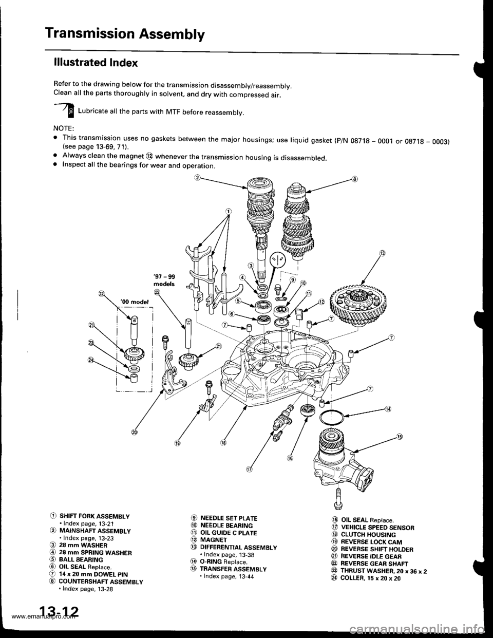
lllustrated Index
Refer to the drawing below for the transmission disassembly/reassembly.Clean all the pans thoroughly in solvent, and drv with comoressed air.
I LuUri""r" utt the parts with MTF before reassembly.
NOTE:
t This transmission uses no gaskets between the major housings; use liquid gasket (p/N 0g718 - 0001 or oE7l8 - 0003)(see page 13-69, 71).. Always clean the magnet @ whenever the transmissjon housing is disassembled.. Inspect all the bearings for wear and operation.
C) sHrFr FoRK ASSEMBLY.Index page, l3-21(a MAINSHAFT ASSEMBLY.Index page, 13-23(9 28 mm WASHER€) 28 mm SPRTNG WASHERO BALL BEARINGa6) OIL SEAL ReDlace.(D 14 x 20 mm DOWEL ptN
G) couNTERSHAFT ASSEMBLY.lndex page, 13-28
NEEDLE SET PLATENEEDLE BEARINGOIL GUIOE C PLATEMAGNETDIFFERENTIAL ASSEMBLY.lndex page, 13-38O-nlNG Beplace.TRANSFER ASSEMBLY.Index page, '13,44
OIL SEAL Replace.VEHICLE SPEED SENSORCLUTCH HOUSINGREVERSE LOCK CAMREVEESE SHIFT HOLDERREVERSE IDLE GEARREVERSE GEAR SHAFTTHRUST WASHER,20 x 36 x 2COLLER, 15 x 20 x 20
aol
@o@@
(D
i9
@@@(9
@@@e3@
13-12
www.emanualpro.com
Page 672 of 1395

Symptom-to-Com ponent Chart
Hydraulic System (cont'd)
NOTES
See flushing procedure, page l4-264 and 265,
BSet idle rpm in gear to specified idle speed. lf still no good, adjust motor mounts as outlined in enginesection of this manual.
clf the large clutch piston O-ring is broken, inspect the piston groove for rough machining.
Dlf the clutch pack is seized or is excessively worn. inspect the other clutches fot wear, and check the orificecontrol valves, CPC valve, and linear solenoid for free movement.
lf the linear solenoid is stuck, inspect the clutches for wear.
lf the 1-2 shift valve is stuck closed. the transmission will not upshift. lf stuck open, the transmission hasno lst gear.
Hlf the 2nd orifice control valve is stuck, inspect the 2nd and 3rd clutch Dacks for wear.
lf the 3-4 orifice control valve is stuck, inspect the 3rd and 4th clutch packs for wear.
Jlf the clutch pressure control valve is stuck closed. the transmission will not shift out of lst gear.
Klmproper alignment of main valve body and torque converter housing may cause ATF pump seizure. Thesymptoms are mostly an rpm-related ticking noise or a high-pitched squeak.
Llf the ATF strainer is clogged with particles of steel or aluminum, inspect the ATF pump and differentialpinion shaft. lf both are OK and no cause for the contamination is found, replace the torque converter.
Mlf the lst clutch feed pipe guide in the end cover is scored by the mainshaft. inspect the ball bearing forexcessive movement in the transmission housing. lf oK, replace the end cover as it is dented. The o-rinounder the guide is probably worn.
N' Replace the mainshaft if the bushing for the 4th feed pipe is loose or damaged, lf the 4th feed pipe is darrFaged or out of round. replace the end cover.' Replace the mainshaft if the bushing for the l st feed pipe is loose or damaged. lf the 1st feed pipe is dam-aged or out of round, replace it.
oA worn or damaged sprag clutch is mostly a result of shifting the transmission in E!. E, or E positionwhile the wheels rotate in reverse. such as rocking the vehicle in snow.
PInspect the frame for collision damage.
lnspect for damage and wear:
l. Reverse selector gear teeth chamfers.
2. Engagement teeth chamfers of countershaft 4th and reverse gear.
3. Shift fork for scuff marks in center.
4. Differential pinion shaft for wear under pinion gears.
5. Bottom of 3rd clutch for swirl marks.
Replace items 1, 2, 3. and 4 if worn or damaged. lf transmission makes a clicking, grinding, or whirring noise,also replace mainshaft 4th gear, reverse idler gear, and countershaft 4th gear in addition to 1,2, 3, or 4.lf differential pinion shaft is worn, overhaul differential assembly, replace ATF strainer, and thoroughly cjeantransmission, flush torque converter. cooler, and lines,lf bottom of 3rd clutch is swirled and transmission makes gear noise. replace the countershaft and final drivenoear,
Be very careful not to damage the torque converter housing when replacing the main ball bearing. you
may also damage the ATF pump when you torque down the main valve body. This will result in ATF pumpseizure if not detected. Use the Drooer tools.
SInstall the main seal flush with the torque converter housing. lf you push it into the torque converterhousing until it bottoms out, it will block the fluid return passage and result in damage.
www.emanualpro.com
Page 680 of 1395

Transfer
4.
Inspection
@E Mako suro lifts, jacks, and safety standsare placod properly lsoe section t).
1. Raise the front of the vehicle, and make sure it issupported securely.
2. Set the parking brake, and block both rear wheelssecurely.
Shift to E position.
Make a reference mark across the propeller shaftand the transfer assembly flanges.
Separate the propeller shaft from the transferassembly.
8 x 1.25 mm32 N.m 13.3 kgl,m,24 lbf.ftlReplace.
14-164
\
6. Set a dial indicator on the transfer assembly flange.then measure the transfer gear backlash.
STANDARD: 0.06 - 0.16 mm (0.002 - 0.006 inl
7. lf the measurement is out of standard, remove thetransfer assembly and adjust transfer gear backlash{see page '14-232 thru 14-2491.
8. Check for fluid leaks between the mating faces oftransfer cover A and cover B.
9. lf there is a fluid leak, remove the cover, and reDlacethe O-ring.
'10. Check for fluid leaks between the mating face of thetransfer assembly and transmission.
11. lf there is a fluid l€ak, remove the transf€r assem-bly, and replace the O-ring,
12. Check the transfer oil seal for damage and fluidle8ks.
13, lf oil seal replacement is required. remove the trans-fer assembly, replace the oil seal, and adjust thetotal starting torque (see page 1+232 thtu ]'4-249||.
NOTE: Do not replace the oil seal with the transferassembly on the transmission.
COMPANION FLANGE
www.emanualpro.com