Page 723 of 1395
3. Install the reverse selector hub on the countershaft
sub-assembly, and press the hub using the special
tool and a press as shown.
DRIVER to mm l.D.07746 - 0030100
REVERSE SEI.ICTORHUB
COUNTERSHAFTSU&ASSEMBLY
Inspection
Clearance Measurement
NOTE: Lubricate all parts with ATF during assembly.
1. Remove the countershaft bearing from the trans-
mission housing lsee page 14-227).
2. Assemble the countershaft parts using the special
tool and a press as described on this page. Do not
install the O-rings during inspection.
R€VERS€ SELECTORHUB
GEAR
NEEDLE BEARING
DISTANCE COLLAR, 28 mmSelective part
2NO GEAR
THRUST NEEDLE BEARING
GEAR
NEEOLE BEARING
GEAR COLIAR
THRUST NEEDLE BEARING
WASHER
CLUTCH ASSEMBLY
(cont'd)
14-207
www.emanualpro.com
Page 724 of 1395

Countershaft
Inspection (cont'd)
3.
4.
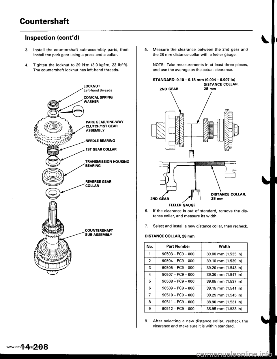
Install the countershaft sub-assembly parts, then
installthe park gear using a press and a collar.
Tighten the locknut to 29 N.m (3.0 kgf.m, 22 lbf.ft).
The countershaft locknut has left-hand threads.
LOCKNUTLe{t-hand threads
CONICAL SPRINGWASHER
PABK GEAR/ONE.WAYCLUTCH/1ST GEARASSEMBLY
NEEDLE BEANING
lST GEAR COLLAR
TRANSMISSION HOUSINGAEARING
REVERSE GEARCOLLAR
COUNTERSHAFTSUB.ASSEMBLY
14-208
5. Measure the clearance between the 2nd gear and
the 28 mm distance collar with a feeler gauge.
NOTE: Take measurements in at least three places,
and use the average as the actual clearance.
STANDARD: 0.10 - 0.18 mm (0.004 - 0.007 in)
OISTANCE COLLAR,28 mm
FEELER GAUGE
6. lf the clearance is out ot standard, remove the dis-
tance collar, and measure its width.
7. Select and install a new distance collar, then recheck.
DISTANCE COLLAR,28 mm
8. After selecting a new distance collar. recheck the
clearance and make sure it is within standard.
2NO GEAR
No.Part Numberwidrh
190503-PCg-00039.00 mm ('1.535 in)
290504-PCg-00039.'10 mm (1.539 in)
?90505-PCg-00039.20 mm {1.543 in)
90507-PCg-00039.30 mm (l.547 in)
90508*PCg-00039.05 mm (l.537 in)
90509-PCg-00039.15 mm (l.541 in)
790510-PCg-00039.25 mm {1.545 in)
890511-PCg-00038.90 mm { L531 in)
990512-PCg-00038.95 mm ( 1.533 in)
www.emanualpro.com
Page 725 of 1395
One-way Glutch
Disassembly/lnspection/Reassem bly
1. Separate countershaft 1st gear from the park gear
by turning the park gear in the direction shown.
PARK GEAR
2. Remove the one-way clutch by prying it up with the
tip of a screwdriver.
COUNTERSHAFT IST GEARONE.WAY CLUTCHInstall in this direction.
ONE.WAY CLUTCH
lST GEAR
COUNTERSHAFT lST GEAR
SCREWDRIVER
14-209
3. Inspect the oarts as follows;
PARK GEARInspect Ior wearand sconng.
ONE.WAY CLUTCHInspect for damageand taulty movement,
4.
lST GEARInspect for wearand scortng.
After the parts are assembled, hold countershaft lstgear. and turn the park gear in the direction shown
to be sure it turns freely. Also make sure the park
gear does not turn in the opposite direction.
COUNTERSHAFT ,IST GEAR
www.emanualpro.com
Page 738 of 1395
Differential
lllustrated Index
'lWD:
SET RING, 80 mmSelective part
10 x 1.0 mm103 N.m (10.5 kgt.m,?5.9 tbtftl
FINAL ORIVEN GEARlnspect for excessive wear,Install in this direction.
BALL BEARINGInspect for rough
DIFFERENTIAI.CARRIERlnspect for cracks.
TRANSFER SHAETDNlvE GEARInspect for excessive
SPEEDOMETERDRIVE GEARInstall in thisdirection.
SNAP RINGInstall in thisdirection.
BALL BEARINGInspect for rough movement,
14-222
2WDl
SET nlNG, 80 mmSel6ctive part
A,U
,gBc
10 x 1.0 mm103 N.m {10.5 kg[.m,75.9 tbt.ftlLeft-hand threads
FINAL ORIVEN GEARInspect for excessive wear,Install in thls direction.
BALL BEABINGInspect for rough
DIFFERENTIAI.CARRIERInspect for cracks.
ROLLER,5 x 10 mm
SPEEDOMETERDRIVE GEARInstall in thisdirection.
SNAP RINGInstall in thisdirection.
BALL BEARING
www.emanualpro.com
Page 739 of 1395
Backlash Inspection
Place the differential assembly on V-blocks.
lnstall the driveshaft and intermediate shaft on the
differential assemblY.
Check the backlash of both pinion gears.
STANDARD: 0.05 - 0.15 mm (0.002 - 0.006 in)
OIFFEBENNAL ASSEMBLY
It the backlash is out of standard, replace the difter-
ential carrier.
1.
DIAL INDICATOR
Bearing Replacement
NOTE: Check bearings for wear and rough movement.
lf bearings are OK, removal is not required.
1. Remove the bearings using a bearing puller.
BEARING PULLER(Commercially available)
lnstall new
snown.
bearings using the sPecial tool
PRESS
14-223
www.emanualpro.com
Page 740 of 1395

Differential
Differential Carrier Replacement
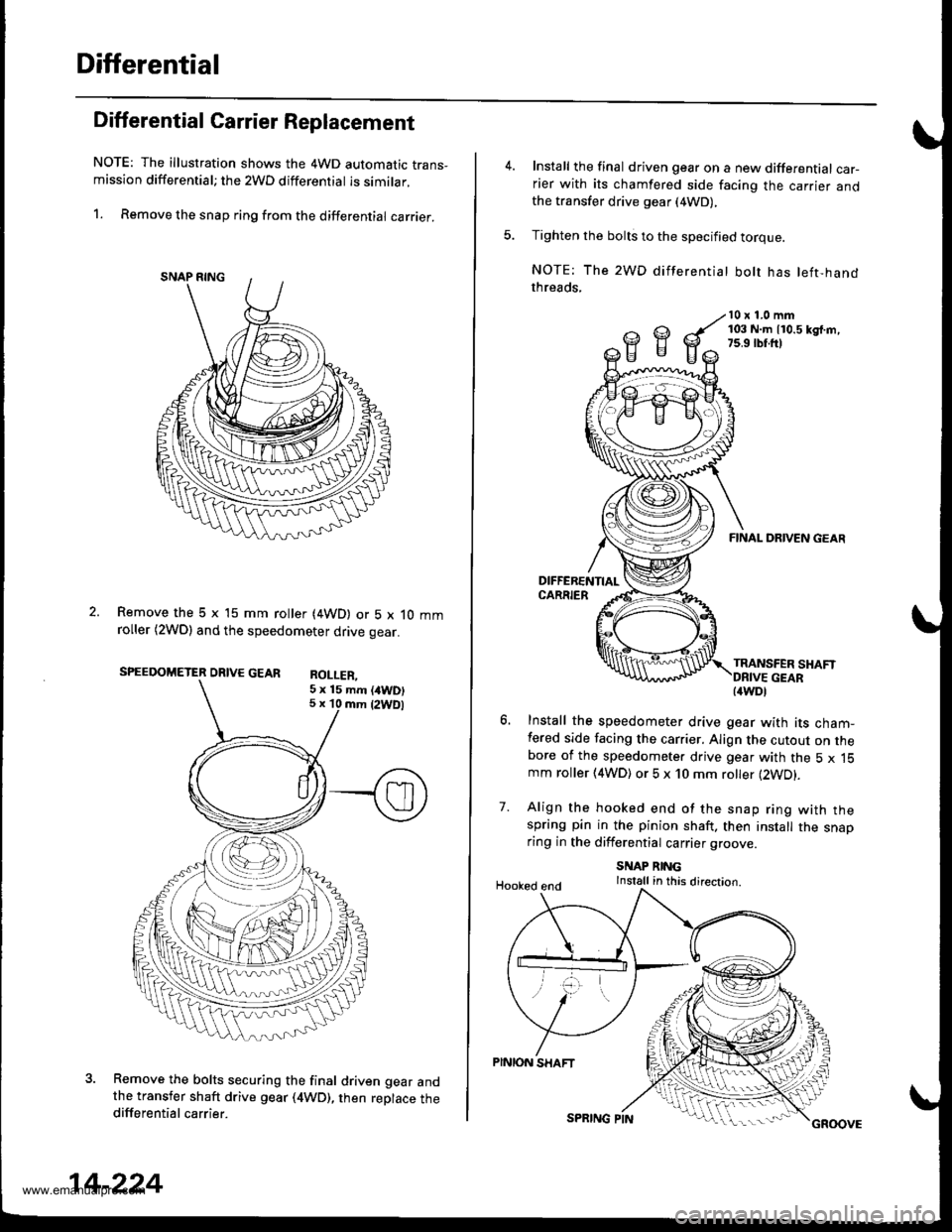
NOTE: The illustration shows the 4WD automatic trans-mission differential; the 2WD differential is similar.
1. Remove the snap ring from the differential carrier.
Remove the 5 x 15 mm roller (4WD) or 5 x 10 mmroller (2WDl and the speedometer drive gear.
SPEEDOMETER DRIVE GEAR RoI I FP
Remove the bolts securing the final driven gear andthe transfer shaft drive gear (4WD), then replace thedifferential carrier.
5 x 15 mm (/tWD)5 x 10 mm {2WDl
14-224
SPRING PINGROOVE
Install the final driven gear on a new differential car-rier with its chamfered side facing the carrier andthe transfer drive gear (4WD),
Tighten the bolts to the specified torque.
NOTE: The 2WD differentiat bolt has left-handthreads,
10 x 1.0 mm103 N.m 110.5 kd.m,7s.9 rbr.ft)
7.
FINAL DRIVEN GEAR
TRANSFER SHAFT
Install the speedometer drive gear with its cham-fered side facing the carrier. Align the cutout on thebore of the speedometer drive gear with the 5 x 15mm roller (4WD) or 5 x 10 mm roller (2WD).
Align the hooked end of the snap ring with thespring pin in the pinion shaft. then install the snaoring in the differential carrier groove
SNAP RINGInstall in this direction.Hooked end
PINION SHAFT
{4WDl
www.emanualpro.com
Page 747 of 1395
Reverse ldler GearPark Stop
lnstallation
1. lnstall the reverse idler gear'
lnstallthe reverse idler gear shaft holder and needle
bearing into the transmission housing, then tighten
the bolts.
6 x 1.0 mm12 N.ft ll.2 kgl']n,a.7 rbl.frl
't.
Inspection/Adi ustment
Set the park lever in the E position.
Measure the distance between the park pawl shaft
and the park lever roller pin as shown.
STANDARD: 72.9 - 73.9 mm {2.87 - 2.91 in)
PARK STOP
PARK PAWL SHAFT
lf the measurement is out of standard, select and
install the appropriate park stop from the table
below.
PARK STOP
PARK STOP
After replacing the park stop. make sure the dis-
tance is within standard.
',.�A\
Measuring /
MarkPart NumberLtL2
124537-PAg-00311.00 mm
(0.433 in)
11.00 mm
(0.433 in)
24538-PAg-00310.80 mm
(0.425 in)
10.65 mm
(0.419 in)
24539-PAg-00310.60 mm
(0.417 in)
10.30 mm
(0.406 in)
14-231
www.emanualpro.com
Page 749 of 1395

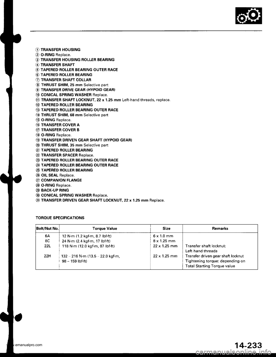
O TRANSFER HOUSING
O o-RING Replace.
O TRANSFER HOUSING ROLLER BEARING
@ TRANSFER SHAFT
O TAPERED ROLLER BEARING OUTER RACE
@ TAPERED ROLLER BEARING
O TRANSFER SHAFT COLLAR
@ THRUST SHIM, 25 mm Selective part
€) TRANSFER DRtvE GEAR (HYPoID GEAR}
@ coNtcAL SPRtNG WASHER Reptace,
@ TRANSFER SHAFT LOCKNUT,22 x 1.25 mm Left-hand rhreads, replace.
(D TAPERED ROLLER EEARING
@ TAPERED ROLLER EEARING OUTER RACE(} THRUST SHIM, 68 mm Selective part
@ O-RING Replace.
@ TRANSFER coVER A
(} TRANSFER COVER B
@ o-RING Replace.
(9 TRANSFER DRIVEN GEAR SHAFT (HYPOID GEAR)
@ THRUST SHIM, 35 mm Selective part
@ TAPERED ROLLER BEARING
@ TRANSFER SPACER Reptace.
@ TAPERED RoLLER BEARTNG OUTER RACE
@ TAPERED ROLLER BEARING OUTER RACE
@ TAPERED BOLLER BEARTNG
@ olL SEAL Replace.
@ COMPANION FLANGE
@ o-RING Replace.
@ BACK-UP RING
@ coNtcAL SPRtNG WASHER Reptace.
@ TRANSFER DRIVEN GEAR SHAFT LOCKNUT,22 x 1.25 mm Replace.
TOROUE SPECIFICATIONS
Boh/Nut No.Torque ValueSizeRemarks
6A
8C
22L
22H
12 N'm (1.2 kgf.m,8.7 lbf.ft)
24 N.m (2.4 kgf.m, 17 lbnft)
118 N.m (12.0 kgim,87 Ibift)
132 216 N.m (13.5 22.0 kgf.m,
98 - 159 lbift)
6x1.0mm
8 x 1.25 mm
22 x 'l.25 mm
22 x 1.25 mm
Transfer shaft locknut:
Left hand threads
Transfer driven gear shaft locknut
Tightening torque: depending on
Total Starting Torque value
14-233
www.emanualpro.com