Page 592 of 1395

Electrical Troubleshooting ('97 Model)
Troubleshooting Flowchart - Countershaft Speed Sensor
Possible Cause
. Loose or faulty connection betweenih€ PCM and vehicle harness. Disconnected countershaft spoedsensor conneclor. Short or open in countershaft speed
. Faulty counteBhaft speed lensor
lf the Honda PGMTester is available:I
J
COUNTERSHAFT SPEED SENSOR
CONNECTOR
ll-'T,ll-rT
ral
YIL__l
Terminal side of male terminals
. OBO ll Scan Tool indicates Codem720.' solt-diagnosis iD!' indicator lightblink3 nine tim6s.
Check and record the freeze datain case it is needed later for problem verification.
Connect the Honda PGM Tester,and test-drive the vehicle withthe tester in Data Link or snap'Shot mode, Make sure the coun-tershaft speed sensor reads thesame as the vehicle speed sensorlVSS).
The countershaft sooed sensor isOK sr this time. Veritv that allconnecloas in the circuit aremaking good contacl.
Check the countershaft speedsensor installation, and check itfor damage.
ls the countershaft speed sen-sor installed properly, and notdamaged?neinstall or roDlaco and recheck.
Measuro CountoBhaft Speed Sen-sor Relbtance at the Sensor Con-nector:1. Disconnect the 2P connectorfrom the countershaft speedsensor connector.2. Measure the resistance of thecountershaft speed sensor.
ls the resistance 400 - 600 o?
To page 14-77
14-76
www.emanualpro.com
Page 593 of 1395
Ch€ck CounteGh!ft Spocd Sonsoifor a Short Cirruit:1. Disconnect the B 125P) con'nector lrom the PCM.2. Check for continuity botweenthe body ground and the B23terminal and 822 term ina Iindividually.
Repair short in tho wirgs b€twoentho 823 ,nd 822 te.minals andthc countaBhaft sp€€d senso..
Mersuro Countorrhrtt Spoed Son-sor qrcuit tor an Open:'1. Connect the countershaftspeed sensor 2P connector,2, Measure the resistancebetween the 823 and 822 termrnals.
Rapair loor€ t.rminll or opon intho wircs betwoon tho 823 .nd822 terminrl! .nd th. countaFshaft specd san3or.
ls the resistance 400 - 600 0?
Check for loo3e terminsl fit in thePCM connecto13. It necess!ry,sub3titulg s known-good PCMand rochock.
PCM CONNECTOR B I25PI
Wire side of lemale terminals
14-77
www.emanualpro.com
Page 594 of 1395
Electrical Troubleshooting {'97 Model)
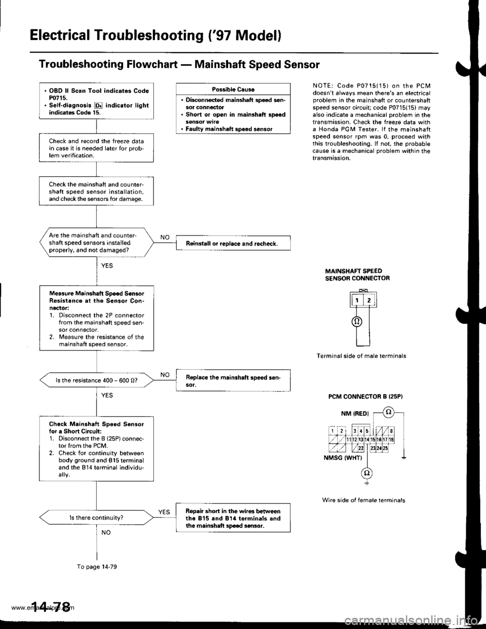
Troubleshooting Flowchart - Mainshaft Speed Sensor
Po$ible Cau3o
. Disconnocted mainshaft speod sen-sot connectot. Short or open in mainsh.ft sp6ed
' Faulty meinshaft spoed sensor
NOTE: Code P0715115) on the PCMdoesn't always mean there's an electricalproblem in the mainshaft or counlersharlspeed sensor circuit; code P0715(15) mayalso indicate a mechanical problem in thetransmission. Check the freeze data witha Honda PGM Tester. lf the mainshaftspeed sensor rpm was 0, proceed withthis troubleshooting. lf not, the probablecause is a mechanical problom within thetransmission,
MAINSHAFT SPEEOSENSOR CONNECTOR
_E_
ItiT,ll-F=r
9t
LJ
Terminal side of male terminals
PCM CONNECTOR B {25P'
Wire side of female terminals
. OBD ll Scan Tool indic.t6 Codem715.. Self-diagnosis E indic.tor lightindicatag Code 15.
Check and record the freeze datain case it is needed later {or prob,lem verification.
Check the mainshaft and counter-shaft speed sensor installation,and checkthe sensors for damage.
Are the mainshaft and counter-shaft speed sensors installedproperly, and not damaged?Reingtall or reolace and recheck.
Meaaure MaiNhatt Spoed Sen3orR6sist!nce at the Sensor Con-necaor:1. Disconnect the 2P connectorfrom the mainshaft speed sen-sor connector.2. lreasure the resistance of themainshaft speed sensor.
ls the resistance 400 - 600 O?
Check Mainahaft Speed Sensortor a Short Circuit:1. Disconnect the B (25P) connec-tor lrom the PCM.2. Check for continuity betlveenbody ground and 815 terminaland the 814 terminal individu-
ReDair short in the wir€6 b€t reenthe 815 and 814 torminals andthe mainsh!ft sp€ed sensor.
To page l4-79
14-78
www.emanualpro.com
Page 595 of 1395
From page 14'78
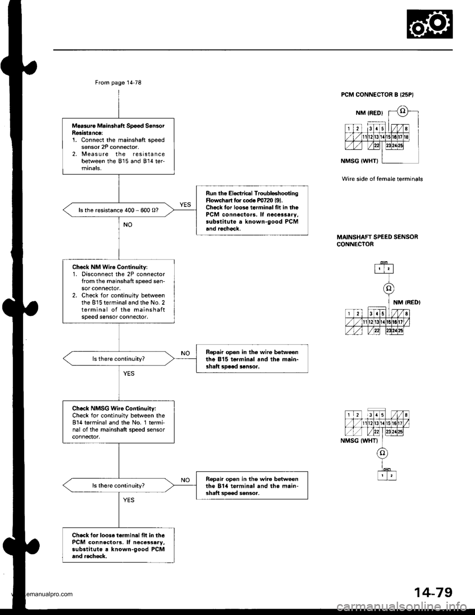
Moasuro Mrin3haft Spoed SanlorResktanco:1. Connect the mainshaft speedsensor 2P connector,2, Measure the resistancebetween the 815 and 814 ter-minals,
Run the Electricrl TroubloshootingFlowchs tor codo m72O l9l.Chock for loo3e torminal fh in thePCM conn6cto.s. It necessarY,substitute a known-good PCMand rochgck.
ls the resistance 400 - 600 O?
Check NM Wiro Continuity:1. Disconnect the 2P connectorfrom the mainshaft speed sen-sor connector.2. Check for continuity betweenthe 815 terminaland the No.2terminal of the mainshaftspeeo sensor conneoor.
Ropair open in the wir6 betw€onthe 815 terminal and the main-shaft sDood $nsoa.
Check NMSG Wire Continuity:Check for continuity between the814 terminal and the No. 1 termi-nal of the mainshaft speed sensorconnector.
R€pai. opon in the wi.o betweenthe Bltl terminal and tho main'3haft sDe€d sensoa,
Ch.ck lor loos. t6rminallit in thePCM connecto13, lf neca3sary,substitute a known-good PCMand rochock.
PCM CONNECTOR B {25P}
Wir€ side of female terminals
MAINSHAFT SPEED SENSORCONNECTOR
14-79
www.emanualpro.com
Page 596 of 1395
Electrical Troubleshooting ('97 Modell
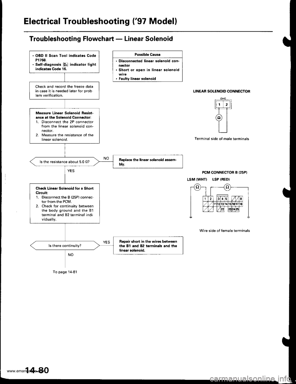
Troubleshooting Flowchart - Linear Solenoid
Possible Caus€
. Disconnocted linear solenoid con-
. Short or oDen in linear solenoid
. Fsultv linear solenoid
SOLENOID CONNECTOR
t-TTI�t]]lt
tl I ? rl-T�r
atll
L_l
PCM CONNECTOR B I25PI
LSM {WHTI LSP {RED)
LINEAR
Terminal side ot male terminals
Wire side of lemale terminals
. OBD ll Scan Tool indicates CodeP1768.. S.lt-diagnosis E indicator lightindicat* Code 16.
Check and record the freeze datain case it is needed later for prob
lem verification.
M€ssurc Linear Solanoid Re3ist-ance ei th€ Solonoid Connoctor:1. Disconnect the 2P connectorfrom the linear solenoid con-nector,2, Measure the resistance ol thelinear solenoid.
ls the resistance about 5.0 O?
Check Linear Solenoid {or a ShortCileuit:1. Disconnect the B (25P) connector from the PCM.2. Check for continuity betweenthe body ground and the B1terminal and 82 terminal individually.
Rooair short in the wires betweenthe Bl end 82 terminek .nd thelinear solenoid.
To page 14-81
www.emanualpro.com
Page 597 of 1395
Ch€ck Ground Lin€:1. Disconnect the A (32P) con-nector from the PCM.2. Check lor continuity betweenterminals Ag and A10 andbetween terminals A22 andA.23.
Repair loose terminal or opon inth€ wires between terminals A9,A10, A22 and A23 and g.ound, andrepair poor ground lG101, G4011.
Measure Linear Solenoid R*ist-
ance:1. Connect the linear solenoid 2P
connector.2. Measure the resistancebetween the 81 and 82 terminals,
Ropair loos€ terminal or op6n in
the wiles between th€ 81 and 82
l6rminals and the linear solenoid.ls the resistance about 5.0 0?
Chock lor loose tarminalfit in thePCM connectors. lf necosaarv,subsiituto a known-good PCMand recheck.
PGl IBLKI
PG2 (ALKI
Wire side of temale terminals
14-81
www.emanualpro.com
Page 602 of 1395
Electrical Troubleshooting ('97 Modell
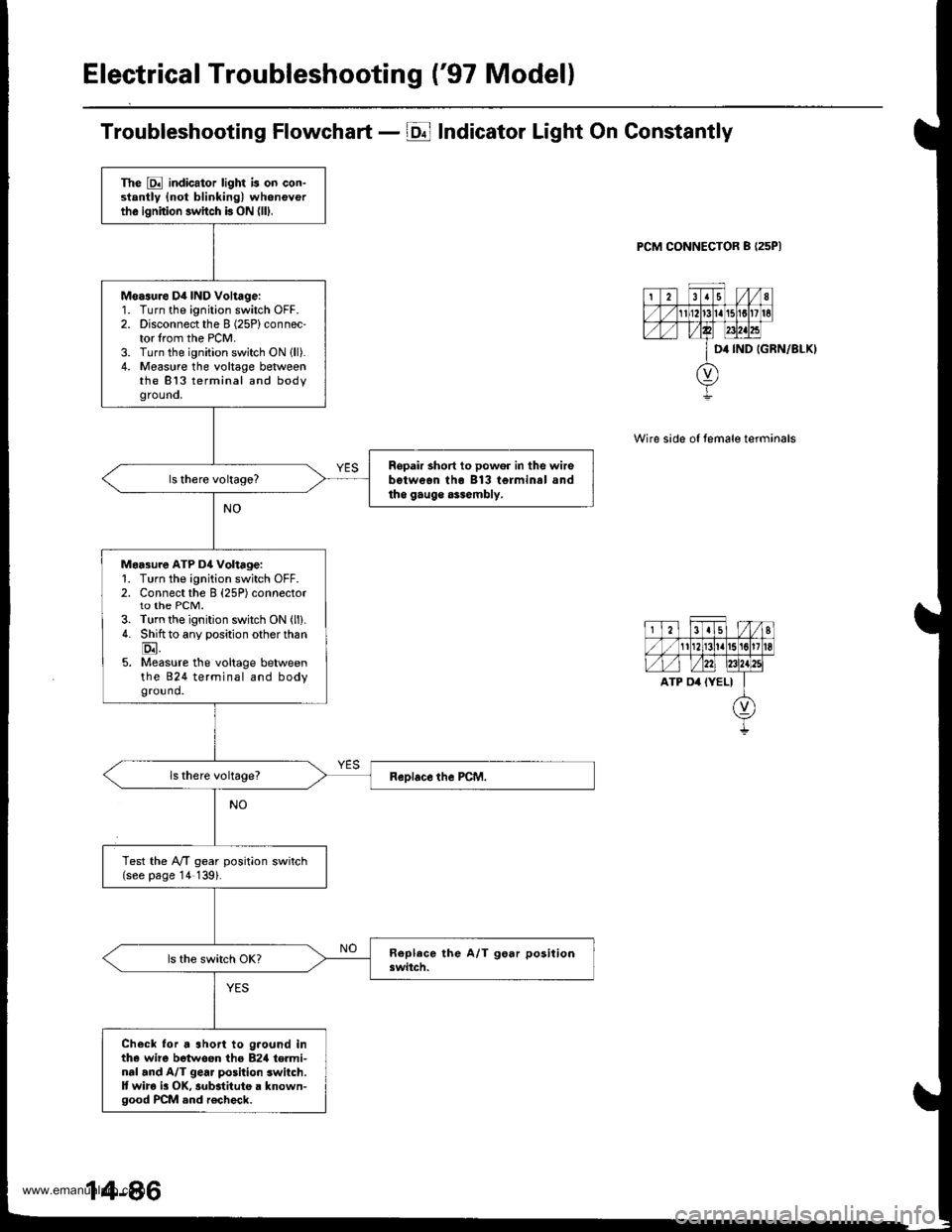
Troubleshooting Flowchart - E Indicator Light On Constantly
PCM CONNECTOR B I25PI
IGRN/8LKI
Wire side of temale terminals
The E indicator light is on con-stantly {not blinking) wheneverthe ignition switch b ON (lll.
Measure D4 IND Voltage:'1.
2.
3.4.
Turn the ignition switch OFF.Disconnect the I (25P) connec-tor lrom the PCM.Turn the ignition switch ON lll).Measure the voltage betweenthe 813 terminal and bodygrouno,
Ropair short to powor in the wirebetwean tho B13 terminal andtho gauge assembly.
Maa3ure ATP D4 Voltage:1. Turn the ignition switch OFF.2. Connect the B (25P) connectorto the PCM.3. Turn the ignition switch ON (ll).
4. Shiftto any position other than
E.5. Measure the voltage betweenthe 824 terminal and bodyground.
Test the lVT gear position switch(see page '14 139).
Check lor a short to g.ound inthe wire betwoen tho B2rl te.minal and A/T gear position switch.It wira i3 OK, substitute a known-good PCM and r€check.
www.emanualpro.com
Page 603 of 1395
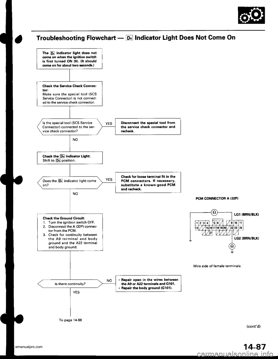
Troubleshooting Flowchart - E Indicator Light Does Not Come On
PCM CONNECTOR A {32PI
Wire side ot temale terminals
LGl IBRN/BLKI
LG2 (BRN/BLKI
(cont'd)
The E indicator light doos notcomo on whon the ignition switchis first turned ON {lll. (lt shouldcome on lor about two aaclnd!.I
Check the Sorvice Check Connec-toriMake sure the special tool 1SCSService Connector) is not connect-ed tothe service check connector,
Di3connect the spccial tool tromthe servica chock connoctor andrechsck.
ls the specialtool (SCS ServiceConnectorlconnected to the ser-vice check connector?
chock th. El Indicator Light:Shift to E position.
Ch6ck for looie terminal fit in thePCM connoctors. ll nocesssry,sub.titule a known-good PCMand rechock.
Check the Ground Circuit:1. Turn the ignition switch OFF.2. Disconnect the A {32P)connec-tor from the PCM.3. Check for continuity betweenthe A9 terminal and bodyground and tho A22 terminaland body ground.
R€pair opon in the wire3 betweenthe Ag or A22 torrninab and G101.Repair the body ground (G1011.
To page 14-88
14-87
www.emanualpro.com