1999 HONDA CIVIC Page 167
[x] Cancel search: Page 167Page 353 of 2189

Troubleshooting
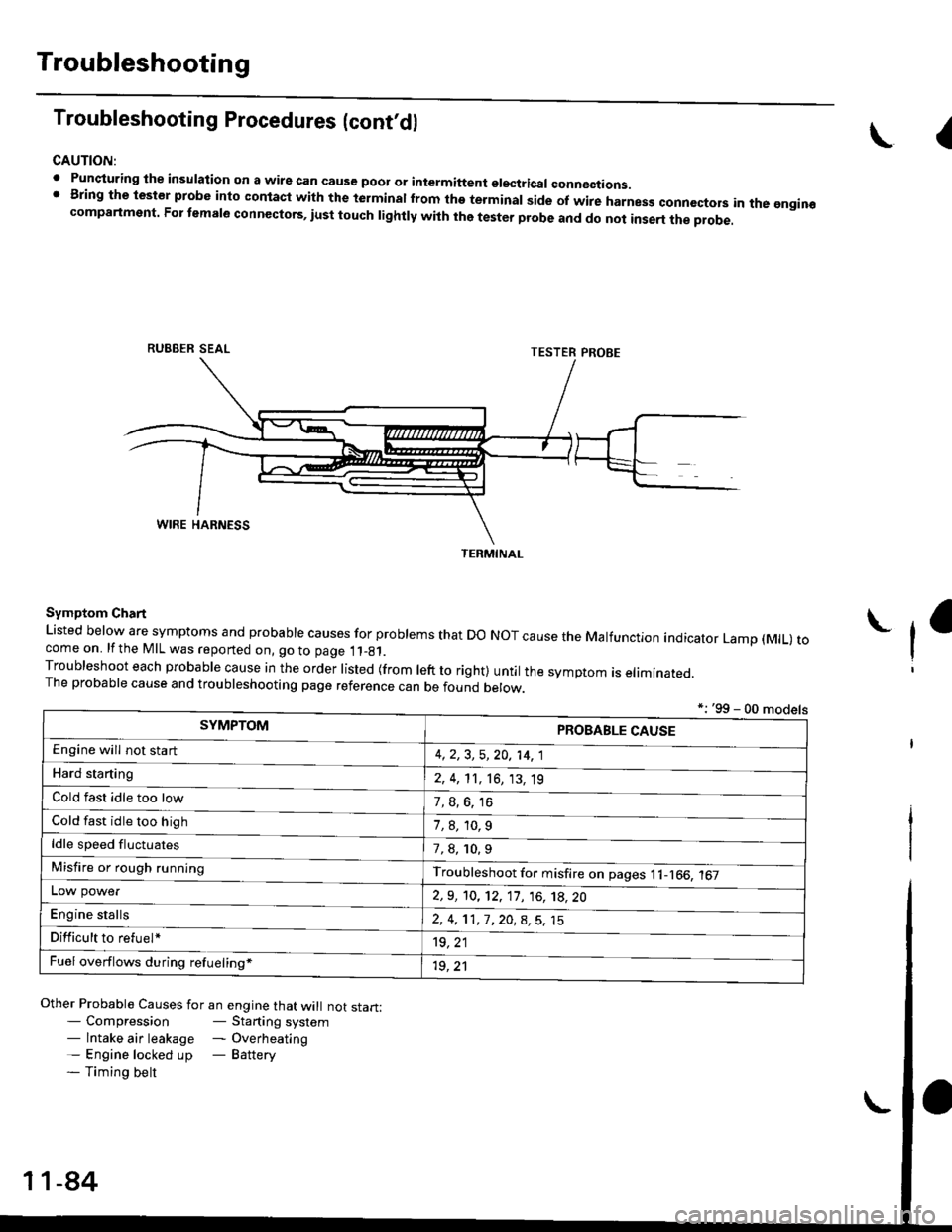
Troubleshooting Procedures (cont,dl
CAUTION:
. Punqturing ihe insulation on a wirs can cause poor or intermiftent electricar connections.I Bring the test€r probe into contacl with the terminatlrom the terminal side of wire harnesg conncctors in the gngin€compartment. For temale connectors, iust touch lightly with the tester probe and do not inse.t the probe.
\I
RUBBER SEAL
Other Probable Causes for an engine that will not start:- Compression- Starting system- lntake air leakage - Overheating- Engine locked up - Battery- Timing belt
TESTER PROBE
Symptom Chart
Listed below are symptoms and probable causes for problems that Do NoT cause the Malfunction indicator Lamp (MlL) tocome on. lfthe MIL was reported on, go to page 11_81.Troubleshoot each probabre cause in the order risted (from reft to right) untir the symptom is eriminated.The probable cause and troubleshooting page reference can be found berow.
L
*: '99 - 00 models
TERMINAL
SYMPTOMPROBABLE CAUSE
4,2,3, 5,20, 14, 1
2, 4, 11, 16, 13, 't9
?, s^6. 16
1,8,10.9
Engine will not sta rt
Hard starting
Cold fast idle too low
Cold fast idle too high
ldle speed fluctuates7,8, 10.9
Troubleshoot for misfire on pages l1-166, 167Misfire or rough running
LOW power
E"g|* "t"lb
2,9, 10, 12, 11, 16, 't8,20
2,4,11,7,20,8,5,15
't9, 21
1r, ,1
Difficult to refuel*
Fuel overflows during refueling*
11-84
Page 367 of 2189

Troubleshooting
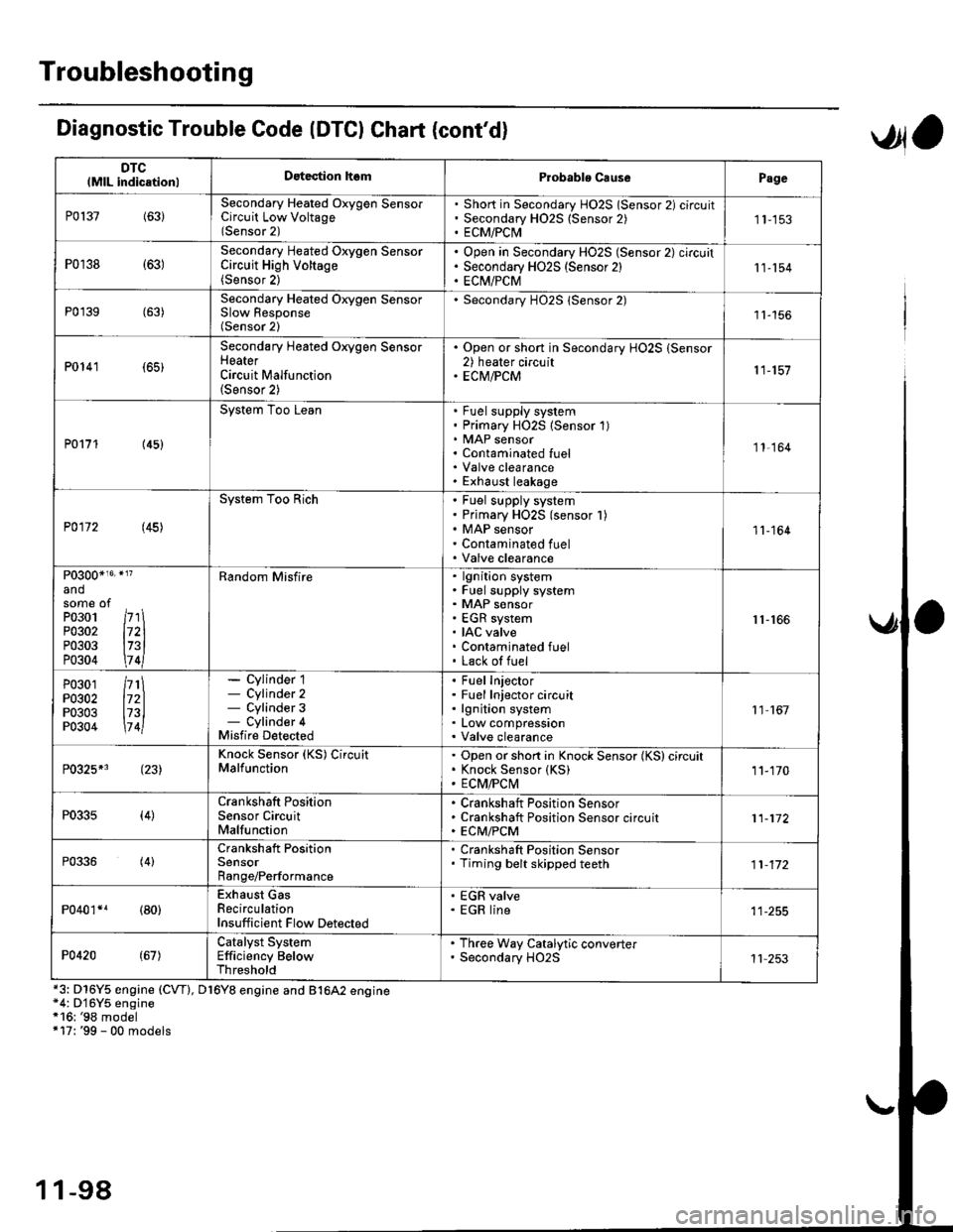
DTClMlL indicationlDatection hsmProbablo CausePage
P0137(63)Secondary Heated Oxygen SensorCircuit Low Voltage(Sensor 2)
Short in Secondary HO2S lSensor 2) circuitSecondary H02S {Sensor 2)ECM/PCI\41 1-153
P0r38 {63)Secondary Heated Oxygen SensorCircuit High Voltage(Sensor 2)
Open in Secondary HO2S (Sensor 2) circuitSecondary HO2S (Sensor 2)EC[I/PCM11-154
P0'139 (63)Secondary Heated Orygen SensorSlow Response(Sensor 2)
Secondary H02S lSensor 2)1l-156
P0141 (65)
Secondary Heated Oxygen SensorHeaterCircuit Malfunction(Sensor 2)
. Open or short in Secondary HO2S (Sensor2) heater circuit. ECM/PCM11-157
P0171 (45)
System Too LeanFuel supply systemPrimary HO2S (Sensor 1)MAP sensorContaminated fuelValve clearanceExhaust leakage
11,164
P0172 (45)
System Too RichFuel supply systemPrimary HO2S (sensor l)MAP sensorContaminated fuelValve clearance
11-164
P0300*16' }l?
andsome ofPo3o1 /r'' \P0302 l72lP0303 l73lP0304 \7 4l
Random Misfirelgnition systemFuel supply systemMAP sensorEGR systemIAC valveContaminated fuelLack of fuel
r1-r66
P0301P0302P0303P0304
/rt\172ll73l\7 4l
- Cylinder 1- Cylinder 2- Cylinder 3- Cylinder 4Misfire Detected
Fuel InjectorFuel Injector circuitlgnition systemLow compressionValve clearance
11 167
P0325*3 (23)Knock Sensor (KS) CircuitMalfunctionOpen or short in Knock Sensor (KS) circuitKnock Sensor {KS)ECM/FCtvl11-170
P0335(4)Crankshaft PositionSensor CircuitMalfunction
Crankshaft Position SensorCrankshaft Position Sensor circuitECM/PCM11-172
P0336(4)Crankshaft PositionSensorRange/Performance
. Crankshaft Position Sensor. Timing belt skipped teeth11-172
P040'�r*r (80)Exhaust GasRecirculationInsufficient Flow Detected
' EGR valve. EGR line
P0420(67)Catalyst SystemEfficiency BelowThreshold
. Th.ee Way Catalytic converter. Secondary HO2S11 253
Diagnostic Trouble Code (DTCI Chat (cont'dl
*3: D16Y5 engine (CVT), D16Y8 engine and B1642 engine*4: D'16Y5 engine*16: '98 model+17: '99 - 00 models
,Jla
1 1-98
Page 369 of 2189

Troubleshooting
Diagnostic Trouble Code (DTGI Chart (cont'dl
*7: D16YS engine (M/T)*8: D16Y5, D'16Y8 engine*9: USA model*14r'97 model*15r '96 model
DTC(MlL indicationlDetection lt6mProbablc CausePage
P1162+1 (48)Primary Heated Oxygen Sensor(Sensor 1) CircuitMalfunction
Open or short in Primarv HO2S (Sensor 1Primary H02S (Sensor 1)1 1- 146
P]163' (61)Primary Heated Oxygen Sensor(Sensor '1) CircuitSlow Response
. Primary HO2S (Sensor 1)
11-145
Pl164*r (61)Primary Heated Oxygen Sensor(Sensor l) Cjrcuit Range/Performance Problem
. Primary HO2S (Sensor 1)
1 1- 150
P1165*? (61)Primary Heated Oxygen Sensor(Sensor 1) Circuit Range/Performance Problem
. Primary HO2S (Sensor 1)
11-150
P1166' (41i
Primary Heated Oxygen Sensor(Sensor '1) Heater System ElectricalProblem
Open or short in Primary HO2S (Sensor 1)heater circuitPrimary HO2S (Sensor 1)ECM/PCM
1 1-'161
P1167*' (41)Primary Heated Oxygen SensorlSensor 1) Heater SystemMalfunction
Open in Primary HO2S (Sensor 1) VS+ circuitPrimary HO2S (Sensor 1) HeaterPrimarv HO2S {Sensor 1)1 1- 163
P1168*' (48)Primary Heated Oxygen Sensor(Sensor 1) LABEL Low Input
. Short in Primary HO2S (Sensor 1) LABELcircuit11-151
Pl169*? (48)
Primary Heated Oxygen Sensor(Sensor 1)IABEL High Input. Open in Primary HO2S (Sensor 1)IABELcircuit. Short in ground circuit11.152
P1259*3(221
WEC System MalfunctionWEC Solenoid ValveOpen or short in WEC SolenoidValve circu itVTEC Pressure SwitchOpen or short in VTEC Pressure SwitchcircuitECM,FCM
Section 6
P1297*s (20)Electrical LoadDetector CircuitLow Input
Electrical Load DetectorElectrical Load Detector circuitECM/PCM11-179
Pr298+' l20l
Electrical LoadDetector CircuitHigh Input
Electrical Load DetectorElectrical Load Detector circuitECM/PCM1 1-181
anosome ofP0301P0302P0303P0304
l71ll72ll73ll7 4l
Bandom Misfirelgnition systemFuel supply systemMAP sensorEGR systemIAC valveContaminated fuelLack ol fuel
11-166
1 1-100
Page 415 of 2189

PGM-FI System
Itil-"w Heated Oxygen Sensor (primary HO2S) (sensor 1l(Dl6Y5 engine with M/Tl
The scan tool indicates Diagnostic Trouble Code (DTC) p1162: A malfunction in the primary Heated OxygenSensor (Primary HO2S) (Sensor 1) circutt.
Doscription
The Primary Heated orygen sensor (Primary Ho2s) {sensor 1) operates over a wide airlfuel range. The primary Ho2S(Sensor 1) is installed in the exhaust manifold.
SEI{SORELEMENT
SENSORTERMINALS
ECM CONNECTOR C (31PIPRIMARY HO2S(SENSOR 1)8PCONNECTOR {Clir5)
female terminalsof femaleterminals
NOTE: lf DTC Pl162 is stored at the same time as DTC Pl167, troubteshoot DTC p1162 first, then recheck for DTC p1167.
(To page 11-147)
- lh6 MIL hes b6on reDorted on.- DTCPl162 ir 3tored.
Problom v6rificationi1. Do the ECM Reset Procedure.2. Start the engine.3. Wait at least tlvo minutes.
Test drive tor several miles withthe transmission in 3rd gear. Holdthe engine speed at 1,500 rpm.
ls DTC P1162 indicatod?
Intermittent tailuro, systom is OKat this timo. Check tor poor con-nections or loose wires at C145(Plimr.y HO2S, Senso. t) andECM,
ls DTC P1162 indicated?
Chock for an open in the wire(lP+ lins):1. Turn the ignition switch OFF.2. Disconnect ECM connector C{31P) from the ECM.3. Disconnect the 8P connectorfrom the Primary HO2S {Sen-sor 1).4. Check for continuity betweenthe Primary HO2S (Sensor 1)8P connector terminal No. 7and ECM connector terminalc23.
Repair open in the wire betwaonECM (C231 end Prim.ry HO2Slsen3or l).
Inspect lor poor terminal to termi-nal contact at the Primary HO2Slsensor 'l I connoctor and ECM.It terminal contect is OK, roplacelh6 Primrry HO2S {Sensor 1}.
11-146
Page 603 of 2189

Inspection
1.surfaces lor
countershaftInspect the gear surfaces and bearang
wear and damage, then measure tne
at points A, B, and C.
Standard: A: 30.000 - 30.015 mm
(1.1811- 1.1817 inl
B: 35.984 - 36.000 mm
(1.i1167 - 1.4173 inl
C: 24.980 - 2i1.993 mm
{0.9835 - 0.9840 in)
Seryice Limit: A: 29.950 mm (1.1791 inl
B: 35.930 mm (1 '1146 in)
C: 24.930 mm 10.9815 in)
Check oil passages
for cloggrng-
ICheck for wearano oamage.
. lf any part of the countershaft is less than
service limit, replace it with a new one.
Inspect for runout.
Standard: 0.02 mm (0.001 inl max.
Seryice Limit: 0.05 mm {0'002 in)
. lf the runout is more than the service limit. replace
the countershaft with a new one.
the
2.
t,3. Install the parts on the countershait
Reassembly
CAUTION:
. Press the 3rd,4th, and sth gears on the countershaft
without lubrication.
. When installing the 3rd. 4th, and 5th geals, support
the shaft on steel blocks and installthe gears using a
pless.
NOTE: Reler to page 13-20 for reassembly sequence'
1. lnstall the needle bearing on the countershaft'
, 36x41 x 25.5mmNEEDLE BEARING
COUNTERSHAFT
2. Assemble the pans below as shown.
NOTE: Check that the fingers of the friction damper
are securely set in the grooves of the 1sv2nd syn-
chro hub.
2ND GEAR
39x/+4x27mmNEEDLE BEARING
SPACER COLLAR
FRICTION DAMPER
SYNCHRO RING
SYNCHRO SPRING
REVERSE GEAR
lST/2NOSYNCHRO HUB
SYNCHRO SPRING
SYNCHRO RING
FRICTION DAMPER
1ST GEAR
(cont'd)
13-23
Page 763 of 2189

From page 14-84
Measule ATP NP Voltage:
1. Shift to all positions other thanpl or E.2. Measure the voltage between
the D13 and 820 or 822 termi-
nals.
Check for ahott in lhe wire
between ths D13 torminal and
tho A/T go.r PGition iwitci, and
in rho E .nd E polition signal
wires Mwgon tho A/T gsar Posi'tion indicrtor and th. A/T gGar
po3ition 3witch. ll wiJ.! .ro OK,
check lor loose torminal fit in the
PCM connoctor3. lf nocet3.rY,
substitute . known-good PCM
and r6check.
ls there baftery voltage?
Measure ATP D4 voh.g€:
1. Shiftto all positions otherthan
E2. Measure the voltage between
the Dg and 820 or 822 termi-nals.
Ch.ck lor 3hort in ths wilo
betweon tho lxl termin.l and tho
A/T ge.r pGhion switch. It wites
are OK. chock fo. looao t€rminal
fit in the PCM conn.ctoB. lf noc_
.*sary, sulFtitute a known-goodPCM .nd rechock.
ls there approx. 5 V?
Moa3ure ATP D3 Vohsge:
1. Shift to all positions other than
tr.2. Measure the voltage betweenthe D8 and 820 or 822 termi-
nals.
Check tor 3hort in the wits
betweon the D8 torminal and the
A/T goer position switch or A/Tgcar position indicltor. It wires
are OK, check for loo3€ torminalfit in tho FCM conn€ctoG. lf nec_
a3$ry, 3ubatitute e known'goodPCM and r.check.
ls there battery voltage?
To page l4'86
PCM CONNECTORS
o t16PlB {25P)
LGl (BRN/BLK)
g t25P)
LGl (BRN/8IJ()
LGl IBRN/BLK)
GRN)
D t16P)
IYEL)
231115 l68 112tV-s-
10n\/t7/ 167I910 t12
I
o zlzz /l/1,/ 113TIL---{O--l\=/LG2{BRN/BLKI
,/t\_
\a t9
ATP NP (LT
Wirc side o{ female termlnals
31158ll25
910111/t6l/17ls lt la112
20) W Wl/l '3111/ll
+LG2 (BBN/BLKI
-<_
ATP D4
LG2 (BRN/BLK}
14-85
Page 1631 of 2189

Lighting System
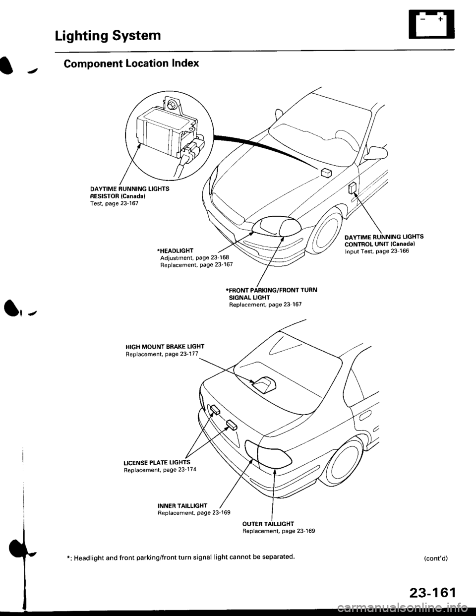
Component Location Index
DAYTIME RUNNING LIGHTSRESISTOR {Canada)Test, page 23 167
DAYTIME RUNNING LIGHTS
CONTROL UNIT (Canadal
Input Test, Page 23 166*HEADLIGHT
Adiustment, page 23-168Replacement, page 23-167
SIGNAL LIGHTReplacement, page 23 167
HIGH MOUNT BRAKE LIGHT
Replacement, page 23-177
LICENSE PLATE LIGHTS
Replacement, Page 23'174
INNER TAILLIGHTReplacement, page 23-169
OUTER TAILLIGHTReplacement, page 23 I69
*: Headlight and front parking/front turn signal light cannot be separated.(cont'd)
23-161