Page 1181 of 2189

Rear Brake Caliper
Disassembly
@f l',lever use an air hose or dry brush to clean
assemblies.
. Use an OsHA-approved vacuum cleaner to
brake
avoid
breathing brake dust.
. Contaminated brake discs or pads reduce stopping
ability.
CAUTION:
. Do not spill brake tluid on the cal; h may damage the
paint; if brake fluid does contact the paint, wash ii
ofl immediatelY with water.
. To prevent spills, cover the hose ioints whh rags or
shop tow€ls.
. Clean all parts in brake fluid and air dry; blow out all
passagss with complessed air.
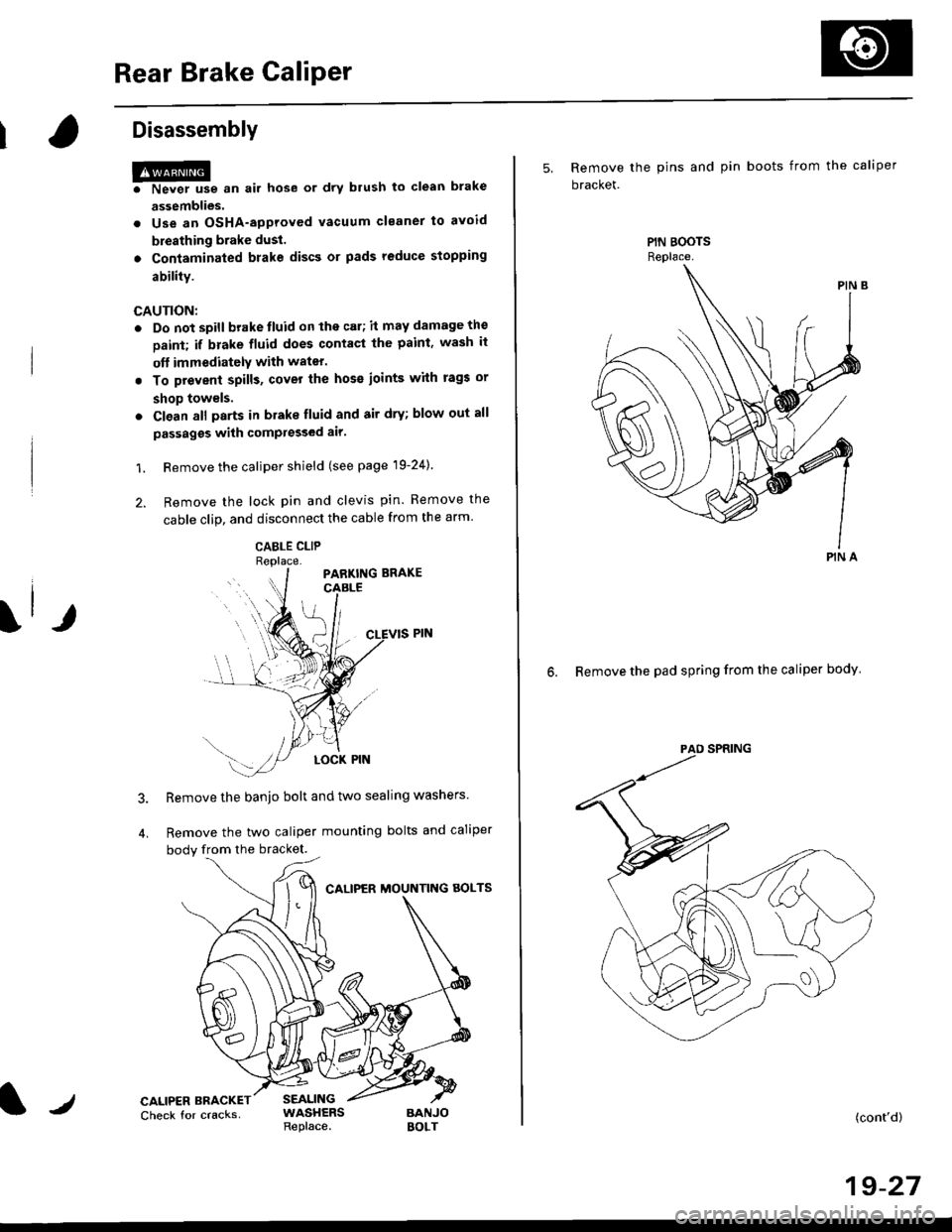
1. Remove the caliper shield (see page 19-24).
2. Remove the lock pin and clevis pin. Remove the
cable clip, and disconnect the cable from the arm
CABLE CLIP
Remove the banjo bolt and two sealing washers
Remove the two caliper mounting bolts and caliper
body from the bracket.
CALIPER MOUNTNG AOLTS
CALIPER BRACKETCheck for cracksSEALINGWASHERSReplace.BANJOBOLT
5, Remove the pins and pin boots from the caliper
bracket.
6. Remove the pad spring from the caliper body
PIN A
(cont'd)
19-27
Page 1213 of 2189

Troubleshooting
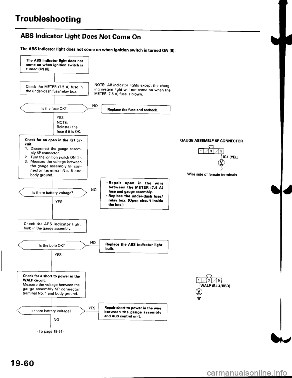
ABS Indicator Light Does Not Come On
YES
NOTE:Reinstallthefuse if it is OK.
The A8S indicator light does not come on when ignition switch is turned ON ll.
NOTE: All indicator tights except the charg,ing system light will not come on when theMETER 17.5 A) ft se is btown.
NO
GAUGE ASSEMBI"Y 5P CONNECTOR
Wire side of female terminals
Tho ABS indicator light does notcome on wh€n ignition switch istu.ned ON {lll.
check the METEB (7.5 A) fuse inthe under-dash fuse/relay box.
Beplace the tu3e and recheck.
Check for an open in th6 lcl cir-cuii:1, Disconnect the gauge assembly 5P connector.2. Turn the ignitjon switch ON l).3. Measure the voltage betweenthe gauge assembly 5P con-nector terminal No. 5 andbody ground.
. Ropair opan in tho wirobotwe€n thc METER t7.5 Attuso and gauge .$cmbly.. Roplacc th. und.r-dash tus./r.l.y box. lop.r cirouit in3idothe box.l
ls there baftery voltage?
Check the ABS indicator lightbulb in the gauge assembly.
ls the bulb OK?
Ch€ck tor a short to power in theWALP circuit:Measure the voltage between thegauge assembly 5P connectorterminal No. I and body ground.
Replir short to power in tho wiiGb.tweon the gruge rs3embly.nd ABS control unh.
ls there battery voltage?
lTo page 19-61)
19-60
Page 1228 of 2189
\il
Modulator Unit
RemovaUlnstallation
CAUTION:
. Do not spill brake tluid on the car; it may damage the paint; it brako lluid does contact the paint, wash it off immedi-
ately with wator.
a Take care not to damage or delorm the brake lin€s during removal and installation.
. To prevent the brake tluid from tlowing, plug and cover the hose €nds and ioints with a shop tow6l or equivalent
mat€rial.
NOTE| Tightentheflare nutsto 15 N.m (1.5 kgnm. l1 lbf.ft).
Removal
'1. Disconnect the modulator unit 10P and Dump motor 2P connectors.
2. Disconnect the brake lines, then remove the modulator unit.
Installaiion
1. Install the modulator unit. then connect the brake lines.
2. Connect the modulator unit 10P and oumD motor 2P connectors.
3. Bleed the brake system.
4. Start the engine, and check that the ABS indicator light goes off.
Fomright-1461
PUMP MOTOR2P CONNECTOR
J
-R
/2e'
t'
TOR UNIT
tt
19-75
Page 1235 of 2189
\:Outer Handle Replacement
NOTE: Raise the glass fully.
'1. Remove:
. Door panel
. Plastic cover (see page 2o-21
2. Pull out the retainer cliP.
6x1.omm Ii.e N.. tr.o rgf.-, I7.2 rbr.fi) ,2
C3.
CYLINDER PROTECTOR
LOCK CYLINDEB
RETAINERCLIP
Remove the bolts, then remove the cylinder protec-
tor, lock cylinder and outer handle.
>: Bolt locaiions,2
CYLINDER
LOCK CYLINDER
CYLINDER ROD
20-5
4. Pull out the outer handle. Pry the outer handle rod
out of its joint using diagonal cutters
NOTE:
a To ease reassembly, note location @ of the outer
handle rod on the joint before disconnecting it.
. Take care not to bend the outer handle rod.
o Use a shop towel to protect the opening in the
ooor.
OUTER HANDLEROD
DIAGONALCUTTERS
SHOPTOWEL
lnstallation is the reverse of the removal procedure
NOTE: Make sure the door locks and opens properly.
BUSHINGReplace.
\
,w.
5.
i4'
Page 1241 of 2189
tOuter Handle Replacement
NOTE: Raise the glass fullY.
1. Remove:
. Door panel
. Plastic cover (see page 20-8)
2. Remove the screws.
>: Screw locations, 3
6x1.0mm6 N.m {0.6 kgf m,4 tbf.ftl
a\
3. Move the latch down, and remove the bolts.
>: Bolt locations,2
6x1.0mm9.8 N,m )11.O kst.n,7.2lbiftl //
4. Pull out the outer handle. Pry the outer handle rod
out of its joint using diagonal cutters.
NOTE:
. To ease reassembly, note location O of the outer
handle rod on the joint before disconnecting it.
. Take care not to bend the outer handle rod.
. Use a shop towel to protect the opening in the
door.
BUSHINGReplace.
OUTERHANDLEROD
5.
o
DIAGONAL \
:"'* ,w,
lnstallation is the reverse of the removal procedure
NOTE: N4ake sure the door locks and opens properly.
SHOP TOWEL
20-11
Page 1247 of 2189
bOuter Handle Replacement
NOTE: Raise the glass fully.
1. Remove:
. Door panel
. Plastic cover (see page 20-14)
2. Pull out the retainer clip.
3.e\
CYLINOER PROTECTOR
LOCK CYLINDER
RETAINERCLIP
Remove the bolts, then remove the cylinder protec-
tor, lock cylinder and outer handle.
>: Bolt locations,2
6x1.omm ]9.8 N.m {1.0 kgf.m,1.2tbl,ttl )_, _-_-,/
CYLINDERPROTECTOR
LOCK CYLINOER
CYLINOER ROD
20-17
4. Pull out the outer handle. Pry the outer handle rod
out of its joint using diagonal cutters.
NOTE:
. To ease reassembly, note location @ ot the outer
handle rod on the joint before disconnecting it.
. Take care not to bend the outer handle rod.
. Use a shop towel to protect the opening in the
door.
DIAGONALCUTTERS
SHOPTOWEL
5. Installation is the reverse of the removal procedure.
NOTE: Make sure the door locks and opens properly.
EUSHINGReplace.
\
,pr,
Page 1253 of 2189

bPosition Adjustment
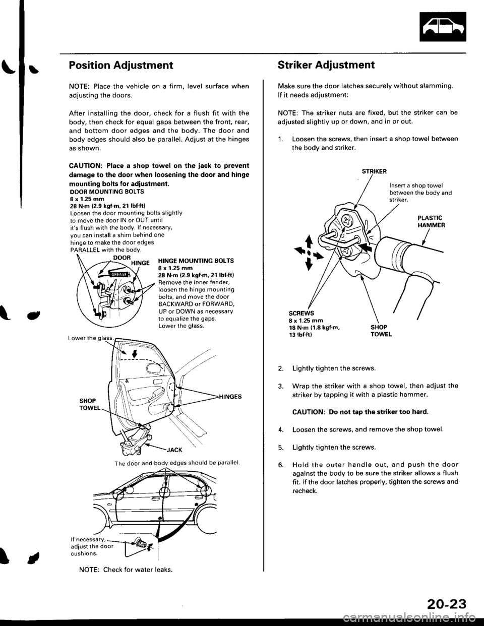
NOTE: Place the vehicle on a firm, level surface when
adjusting the doors.
After installing the door, check for a flush fit with the
body, then check for equal gaps between the front, rear,
and bottom door edges and the body. The door and
body edges should also be parallel. Adjust at the hinges
as shown,
CAUTION: Place a shop towel on the iack to prevent
damage to the door when loosening the door and hinge
mounting bohs for adiustment.
DOOR MOUNTING BOLTS8 x 1.25 mm28 N.m {2.9 kgf.m.21 lbt'ft}Loosen the door mounting bolts slightly
to move the door lN or OUT until
it's flush with the body. lf necessary,
vou can installa shim behind one
hinge to make the door edgesPARALLEL with the body.
J
HINGE MOUNTING BOLTSI x 1.25 mm28 N.m (2.9 kgf.m,21 lbtft)Remove the inner fender,loosen the hinge mountingbolts, and move the doorBACKWARD or FORWARD,UP or DOWN as necessaryto equalize the gaps.Lower the glass.
\
The door and body edges should be parallel-
ifF t
NOTE: Check for water leaks.
20-23
Striker Adjustment
lvlake sure the door latches securely without slamming.
lf it needs adjustment:
NOTE; The striker nuts are fixed, but the striker can be
adjusted slightly up or down, and in or out.
'L Loosen the screws, then insert a shop towel between
the body and striker.
Insert a shop towelbetween the body and
sc8Ews8 x 1.25 mm18 N.m (1.8 kgf.m,13 tbtftl
PLASTIC
2. Lightly tighten the screws.
3. Wrap the striker with a shop towel, then adjust the
striker by tapping it with a plastic hammer.
CAUTION: Do not tap the striker too hard.
4. Loosen the screws. and remove the shop towel.
Lightly tighten the screws.
Hold the outer handle out, and push the door
against the body to be sure the striker allows a flush
fit. lf the door latches properly, tighten the screws and
recheck.
5.
Page 1255 of 2189
|}Mirror Holder/Cover Replacement
CAUTION: Put on gloves to protecl your hands.
L Carefully pry out the mirror holder with a flat tip
screwdriver as shown.
Installation is the reverse of the removal procedure.
NOTE: Apply grease to the locations indicated by
the arrows.
>: Sc.ew locationsA >, 3 s>,2
I
ry
To remove the screws,pull the seal away.
PIVOT
-6rJOINT PIN
-G{
J
6)drD
)
I
SHOP TOWEL
Rearview Mirror Replacement
1. Remove the rubber damper.
2. Pry the cover off using the end of a flat tip screw-
drivef.
CAUTION: When prying with a flat-tip screwdriver,
wrap it with a shop towel to prgvant damage.
3. Remove the screws, then remove the rearview mir-
ror,
4. Installation is the reverse of the removal procedure.
SCREW5x0.8mmil N.m lo.a kgf.m,3 lbf.ftl
SHOP TOWEL
20-25