Page 573 of 2189

Slave Gylinder
Removal/lnstallation
CAUTION:
. Do not spill brake tluid on the vehicle; it may damage
the paint; if brake fluid does contact th€ paint, wash
it off immodiatoly with water,
. Plug the end ot the clutch line with a shop towel to
prevsnt brake fluid from coming oul.
-61'srp", High Temp Urea crease (p/N
08798 - 90021.
: Brake Assembly Lube or equivalent rubber
grease.
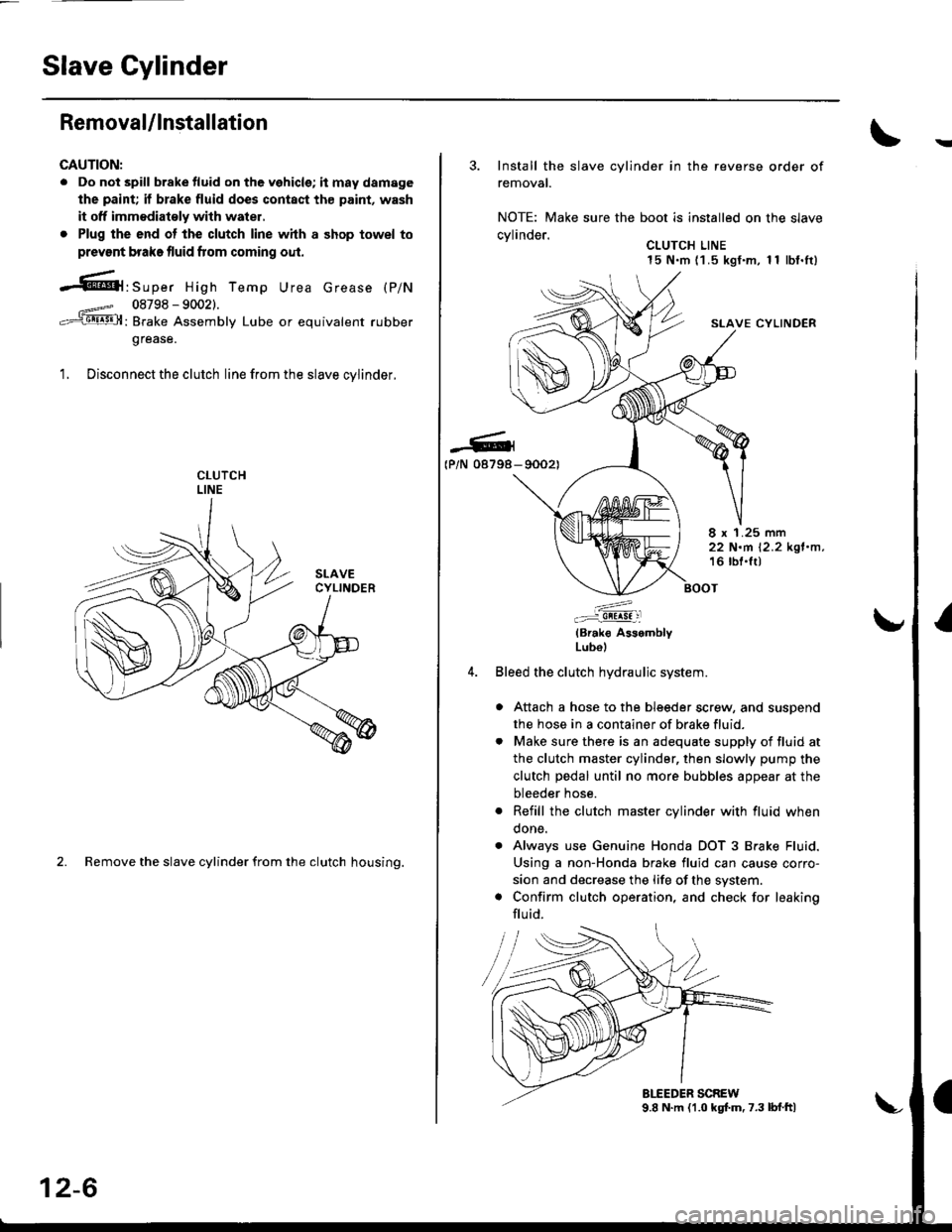
1. Disconnect the clutch line from the slave cvlinder.
2. Remove the slave cylinder from the clutch housing.
12-6
3. Install the slave cylinder in the reverse order of
removal.
NOTE: Make sure the boot is installed on the slave
cvlinder.. CLUTCH LINE15 N.m (1 .5 kgf.m, 1 1 lbf.It)
SLAVE CYLINDER
-G4(P/N 08798- 90021
8 x 1.25 mm22 N.m 12.2 kgl.n,16 lbl.lt)
:^..:i!!!!! :l
(Brak€ AssemblyLubol
Bleed the clutch hydraulic system.
a Attach a hose to the bleeder screw, and suspend
the hose in a container of brake fluid.
. Make sure there is an adequate supply of fluid at
the clutch master cylinder, then slowly pump the
clutch pedal until no more bubbles appear at the
bleeder hose.
. Refill the clutch master cylinder with fluid when
done.
. Always use Genuine Honda DOT 3 Brake Fluid.
Using a non-Honda brake fluid can cause corro-
sion and decrease the life of the system.
. Confirm clutch operation, and check for leaking
flu id.
Page 618 of 2189

Mainshaft Thrust ShimI
I
Adjustment (cont'dl
b.Attach the mainshaft holder to the mainshaft asfollows:
NOTEI
. Back-out the mainshaft holder bolt and loosen
the two hex bolts.
. Fit the holder over the mainshaft so its lip istoward the transmission.
. Align the mainshaft holder's lip around thegroove at the inside of the mainshaft splines,then tighten the hex bolts.
MAINSHAFT HOLOERBOLT
MAINSIIAFTHOLDER07GAJ-PG20110
d.
Seat the mainshaft fully by tapping on the end witha plastic hammer.
Thread the mainshaft holder bolt in until it just
contacts the wide surface of the mainshaft base.
u
e. Zero a dial gauge on the end ofthe mainshaft.
MAINSHAFT HOLDER07cAJ_PG20110
Turn the mainshaft holder bolt clockwise: stop turn,ing when the dial gange has reached its maximummovement. The reading on the dial gauge is theamount of mainshaft end olav.
CAUTION: Turning the mainshaft holder bolt morethan 60 degre€s after the needle ot the dial gauge
stops moving may damage the iransmission.
lf the reading is within the standard. the clearance iscorrecl.
lf the reading is not within the standard, recheck theshim thickness.
Standard: 0.11 - 0.18 mm {0.00it - 0.007 in}
t.
\,J
Page 670 of 2189

Mainshaft Thrust Clearance
Adjustment (cont'd)
13. Check the thrust clearance in the manner describedoetow.
CAUTION: Measuremenl should be made at roomtempetature.
a. Slide the mainshaft base over the mainshaft.
MAINSHAFT EASE07GAJ - PG20.130
b. Attach the mainshaft holder to the mainshaft asfollows:
NOTE:
. Back-out the mainshaft holder bolt and loosenthe two hex bolts.. Fit the holder over the mainshaft so its lip istowards the transmission.. AIign the mainshaft holder.s Iip around thegroove at the inside of the mainshaft splines,then tighten the hex bolts.
MAINSHAFT HOLOERBOLT
MAINSHAFT
[--F-e
l6fffi l
rx| - \-/ I/ Borrs
ff
MAINSHAFTHOLDER07GAJ - PG20110
MAINSHAFT BASE07GAJ - PG20130
13-90
c. Seat the mainshaft fully by tapping its end with aplastic hammer.
d. Thread the mainshaft holder bolt in untjl it justcontacts the wide surface of the mainshaft base.
e. Zero a dial gauge on the end ofthe mainshaft.
f. Turn the mainshaft holder bolt clockwise; stooturning when the dial gauge has reached itsmaxtmum movement. The reading on the dialgauge rs the amount of mainshaft end Dlav.
CAUTION: Turning tho mainshaft holder boltmore than 60 degrees after the needle of the dialg€uge stops moving may damage the transmis_ston.
07cAJ _ PG20110
g. lf the reading is within the standard, the clear-ance is correct.
lf the reading is not within the standard. recheckthe shim thickness.
Standard: 0.11 - O.18 mm {0.004 - 0.007 in}
DIAL GAUGE
Page 700 of 2189

Description
Hydraulic Control (cont'dl
Regulator Valve
The regulator valve maintains a constant hydraulic pressure from the ATF pump to the hydraulic control system, whitealso furnishing fluid to the lubricating system and torque converter. The fluid from the ATF pump flows through B and 8,.The regulator valve has a valve orifice. The fluid entering from B flows through the orifice to the A cavity. This pressure ofthe A cavity pushes the regulator valve to the right side, and this movement of the regulator valve uncovers the fluid portto the torque converter and the relief valve. The fluid flows out to the torque converter, and the relief valve and regulatorvalve moves to the left side. According to the level of the hydraulic pressure through B, the position of the regutator vatvechanges and the amount of the fluid from B' through D and c also changes. This operation is continued. maantaining theline pressure,
NOTE: When used. "|eft" or "right" indicates direction on the illustration betow.
ENGINE NOT RUNNING
TOROUE CONVERTER
ENGINE RUNNING
To TOROUE CONVERTER Lubrication
Stator Roaction Hydraulic Prossur6 Control
Hydraulic pressure increases according to torque, are performed by the regulator valve using the stator torque reaction.The stator shaft is splined with the stator in the torque converter, and its arm end contacts the regulator sprang cap. whenthe vehicle is accelerating or climbing (Torque Convert€r Range), the stator torque reaction acts on the stator shaft, andthe stator arm pushes the regulator spring cap in the direction of the arrow in proponion to the reaction. Jne stator reac-tion spring compresses, and th€ reoulator valve moves to increase the line pressure which is regulated by the regulatorvalve. The line pressure reaches its maximum when the stator torque reaction reaches its maximum.
STATOR SHAFT ARM
REGULATOR VALVE
14-22
STATORATOR SHAFT ARM
SPRING CAP
Page 736 of 2189

Electrical Troubleshooting ('96 - 9g Modelsl
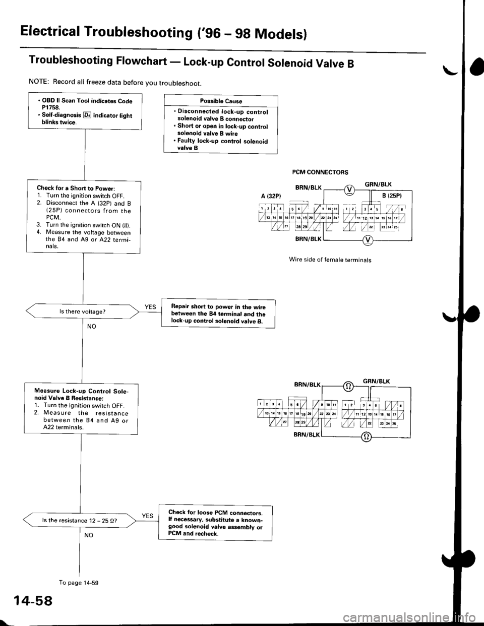
Troubleshooting Ftowchart - Lock-up control sorenoid Varve B
Possible Cause
. Disconnected lock-up controlsolenoid valve B connector' Short or open in lock-up controlsolonoid valve B whe. Faulty lock-up control solenoidvalve B
PCM CONNECTORS
Wire side of female terminals
. OBD ll Scan Tool indicrtes CodeP1758.. Self-diagnosis E indicrtor lightblinkstwice.
Check for a Shon to Power:1. Turn the ignition switch OFF.2. Disconnect the A (32p) and B(25P) connectors from thePCM,3. Turn the ignition switch ON t).4. Measure the voltage betweenthe 84 and A9 or A22 termi-nals.
Repeir short to power in the wirebetween the 84 teiminal and thelock-up control solenoid valve B.
Moasure Lock-up Control Sole-noid Valve B Resistance:1. Turn the ignition switch OFF.2. Measure the resistancebetween the 84 and Ag orA22 terminals.
Check for loose FCM connectors,lf necessary, substitute a known-good solenoid valve assembly olP1CM and rech6ck.
ls the resistance 12 - 25 O?
NOTE: Record all freeze data before you troubleshoot.
A {32P)
To page 14-59
t-
Page 816 of 2189

Valve Caps
Description
Caps with one projected tip and one flat end are
installed with the flat end toward the inside of the
valve body.
Caps with a projected tip on each end are installed
with the smaller tip toward the inside of the valve
body. The small tip is a spring guide.
Toward outside of valvo body.
Toward insido ot valvo body.
Caps with one projected tip and hollow end are
installed with the tip toward the inside of the valve
body. The tip is a spring guide.
Towa.d outside o, valv6 bodv.
I
14-138
Toward insid€ of valv6 bodv.
Caps with hollow ends are installed with the hollow
end away from the inside ofthe valve body.
Caps with notched ends are installed with the notch
toward the inside of the valve body.
Caps with flat ends and a hole through the center are
installed with the smaller hole toward the inside of
the valve bodv.
Toward outsido of valve bodv.
Efla
Toward inlido ot valve bodv,
Caps with flat ends and a groove around the cap are
installed with the grooved side toward the outside of
the valve body.
Toward oulsido of valv6 body.
"-\"h
,A
\za9
Sectional view.
Toward insido ol valvo body.
Page 830 of 2189
Countershaft
Disassembly/Reassembly
1. Using a hydraulic press, press out the countershaftwhile supporting 4th gear.
NOTE: Place an attachment between the press andthe countershaft to prevent damage to the shaft.
CAUTION: Do not allow the countershaft to fall andhit the g.ound when pressed clear.
14-152
2. Assemble the parts on the countershaft as shownoetow.
NOTE;
. Lubricate all parts with ATF during assembly.. Before installing the O-rings, wrap the shaft splineswith tape to prevent damaging the O_rings.
4TH GEAR
NEEDLE EEARING
DISTANCE COLLAR, 28 mmSelective part.
2ND GEAR
THRUST NEEOLE BEARING
3RD GEAR
NEEDI.E EEARING
3RO GEAR COLLAR
THRUST NE€OLE BEARING
SPLINED WASHER
3RD CLUTCH ASSEMBLY
O.RINGSReplace.
COUNTERSHAFT
Page 842 of 2189
Glutch
Reassembly (cont'd)
7. Installthe snap ring.
Removs the special tools.
Install the disc spring.
NOTE: Install the disc spring in the direction
shown, except 2nd clutch.
SNAP RING
8.
o
14-164
h
10.
ll.
Soak the clutch discs thoroughly in ATF for a mini-
mum of 30 minutes.
Starting with a clutch plate, alternately install the
clutch plates and discs. Install the clutch end plate
with flat side toward the disc.
NOTE: Before installing the plates and discs, make
sure the inside of the clutch drum is free of din orother foreign mafter.
CLUTCH END PLATEInstall in this direcrion.
12. Installthe snap ring.
SCREWDRIVER
SNAP RING