1999 HONDA CIVIC Engine
[x] Cancel search: EnginePage 1414 of 2189
Heater Unit
Replacement (cont'dl
6.
7.
8.
9.
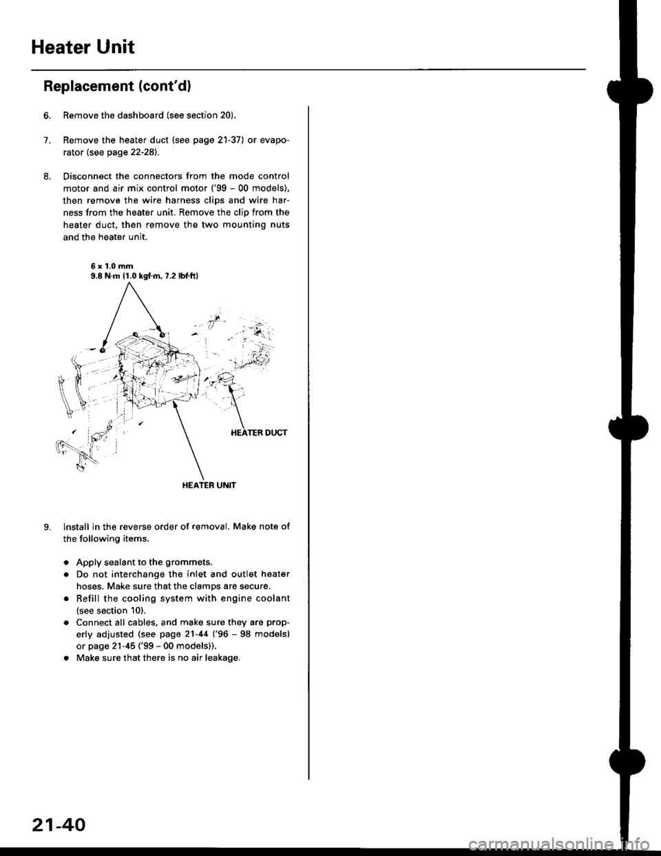
Remove the dashboard (see section 20).
Remove the heater duct (see page 21-37) or evapo-
rator (see page 22-28).
Disconnect the connectors from the mode control
motor and air mix control motor ('99 - 00 models),
then remove the wire harness clips and wire har-
ness from the heater unit. Remove the clip from the
heater duct, then remove the two mounting nuts
and the heater unit.
6x1.0mm9.8 N.m 11.0 kgl.m,7.2 lbf.ftl
HEATER UNIT
lnstall in the reverse order of removal. Make note of
the following items.
Apply sealant to the grommets.
Do not interchange the inlet and outlet heater
hoses. Make sure that the clamps are secure.
Refill the cooling system with engine coolant
(see section 10).
Connect all cables, and make sure they are prop-
erly adjusted (see page 21-44 (96 - 98 models)
or page 21-45 ('99 - 00 models)).
Make sure that there is no air leakage.
21-40
Page 1442 of 2189
Troubleshooting
A/C System (cont'd)
From page 22-11
. _Ff,, __
I11213[
,r,il*"-T",-.r-'..owrRE I
To page 22-19 1'96 - 98 models)
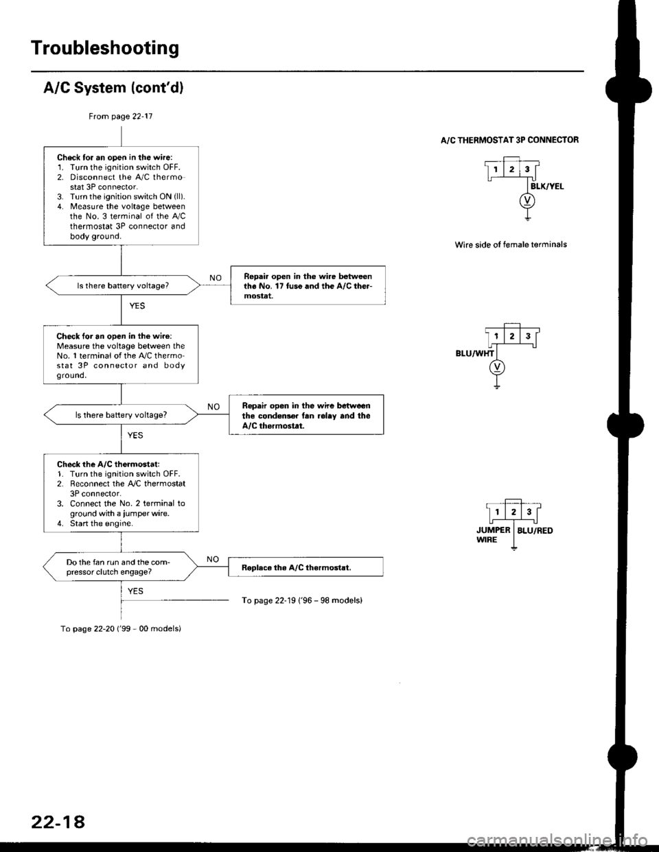
A/C THERMOSTAT 3P CONNECTOR
Wire side oI female terminals
Check tor an open in the wire:1. Turn the ignition switch OFF.2. Disconnect the A/C thermostat 3P connector.3. Turn the ignition switch ON (ll).
4. Measure the voltage betweenthe No. 3 terminal of the Ay'Cthermostat 3P connector andbody ground.
Repai. open in the wire betweentho No. 17 tuso and the A/C the.-mostat.
Check loi an open in the wi.e:Measure the voltage between theNo. 1 terminal of the A,/C thermostat 3P connector and bodyground,
Ropair open in the wire betwoenthe condedlo. lan rolay and theA/C thormostat.
ls there battery voltage?
Check the A/C th6rmostat:1. Turn the ignition switch OFF.2. Reconnect the A,/C thermostat3P connector.3. Connect the No. 2 terminal toground with a iumperwire.4. Start the engine.
Do the fan run and the com-pressor clutch engage?
To page 22-20 ('99 - 00 models)
22-18
Page 1447 of 2189
A/C System Torque Specifications
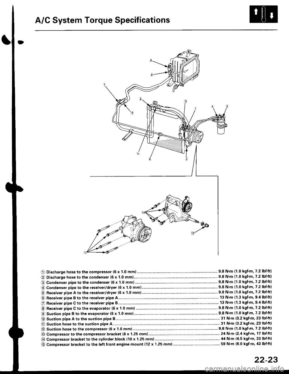
O Discharge hose to the compressor (6 x 1.0 mml ............... .. .... ...............' 9.8 N'm {1.0 kgf'm,7.2 lbf'ftl
@ Discharge hose to the condenser {6 x 1.0 mm1................... '... ...... . ......... 9.8 N'm 11.0 kgf'm, 7.2 lbf'ft}
O Condenser pipe to the condenser 16 x 1,0 mm)...............'. . . . ...........'..... 9.8 N'm (1.0 kgl'm, 7.2 lbt'ft)
@ Condensel pipe to the receivel/dryer (5 x 1.0 mml......... ..... . ... . '.......... 9.8 N'm (1.0 kgl'm, 7.2 lbt'ft)
O Receiver pipe A to the leceiver/dryer {6 x 1.0 mm)......... ... .......... .. . . .... 9.8 N'm 11.0 kgf'm. 7.2 lbl'ft)
@ Receiver pipe B to the receiver pipe A 13 N m (1.3 kgf'm, 9.'l lbf'ft)
O Receiver pipe C to the receiver pipe B 13 N m (1.3 kgf'm, 9.4 lbnftl
@ Receiver pipe C to the evaporator {6 x 1.0 mm) ....... 9.8 N'm (1.0 kgf'm, 7.2 lbtftl
O Suction pipe B to the evaporator (6 x 1.0 mml................ . .........'......'....... 9.8 N'm (1.0 kgf m, 7.2 lbf'ftl
e0 Suction pipe A to the suction pipe B ...'. . ...... . ... ...... 31 N'm (3.2 kgt'm, 23 lbf'ftl
O Suction hose to the suction pipe A... ............ . . '......... 31 N'm (3.2 kgl'm, 23 lbf'ft|
@ Suction hose to the compressor (6 x 1.0 mm)................... .. . ... .. ............ 9.8 N'm (1.0 kgf'm' 7.2 lbf'ft|
@@ Compressor to the compressor bracket (8 x 1.25 mm)... ..-........'.'......-.......24 N'm (2 'l kgf'm, 17 lbf ftl
@ Compressor bracket to the cytinder block (10 x 1.25 mml 44 N'm l'1.5 kgf'm, 33 lbf ftl
@ Compressor bracket to the left front engine mounl {12 x 1.25 mm}..... . . . . .. ................. ... ... 59 N'm (6.0 kgf'm, '|i} lbf ftl
22-23
Page 1448 of 2189
A/C System Service
Performance Test
The performance test will help determine if the air con-
ditioner system is operating within specifications.
Use only service equipment that is U.L.-listed and is cer-
tified to meet the reouirements of SAE J2210 to remove
HFC-134a (R-134a) from the air conditioner system.
CAUTION: Exposure to air conditionor rofrigerant and
lubricant vapor or mist can irrilalo €yes, nose and
throat. Avoid breathing tho air conditioner rstrigerrnt
and lubricant vapor or mist,
lf accidental system discharge occurs, ventilate work
area before resuming service.
R-134a service equipment or vehicle air conditioner sys-
tems should not be pressure tested or leak tested with
compressed air.
@ some mixtur$ of air and R-134a have been
shown lo b9 combustible rt glgvatad pr€ssur63 and can
resull in tire 01 oxplosion causing inlury ot property
damage. Never uao compre33ed air to pressure t99t R-
134a ssrvico 6quipmsnt or vohicla air conditioner sys-
tems.
Additional health and safety information may be obtained
from the refrigerant and lubricant manufacturers.
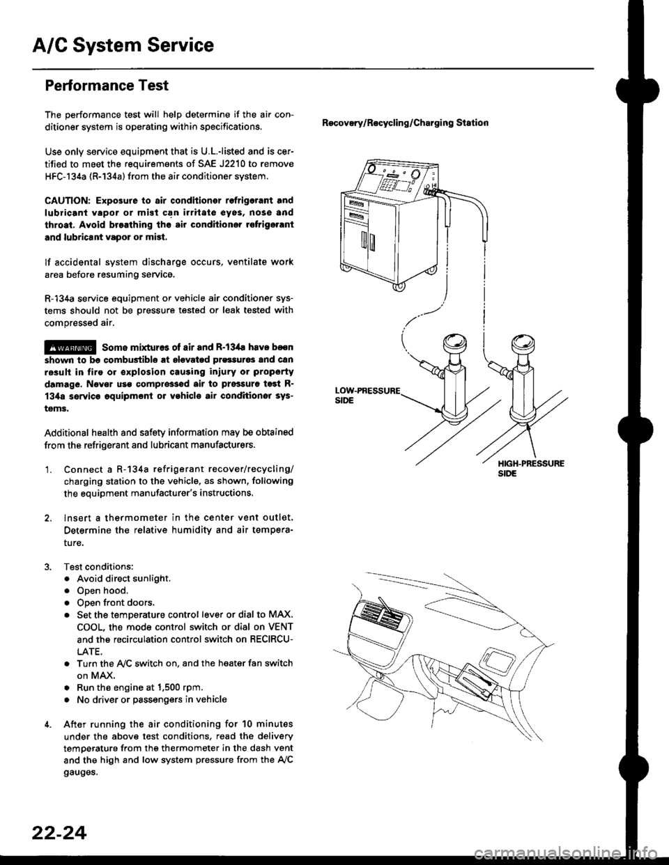
'1. Connect a R-134a refrigerant recover/recycling/
charging station to the vehicle, as shown, following
the equipment manufacturer's instructions.
2. lnsert a thermometer in the center vent outlet.
Determine the relative humidity and air tempera-
ture,
Test conditions:
. Avoid direct sunlight.
. Open hood.
. Open front doors.
. Set the temDerature control lever or dial to MAX,
COOL, the mode control switch or dial on VENT
and the recirculation control switch on RECIRCU-
LATE.
. Turn the A,/C switch on. and the heater fan switch
on MAX.
. Run the engine at 1,500 rpm.
. No driver or passengers in vehicle
After running the air conditioning for 10 minutes
under the above test conditions, read the delivery
temperature from the thermometer in the dash vent
and the high and low system pressure from the A,/C
gauges.
Recovery/Rocycling/Charging Station
22-24
Page 1454 of 2189
Compressor (SANDENI
Replacement
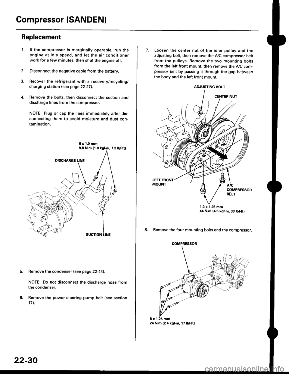
1.lf the compressor is marginally operable, run the
engine at idle speed, and let the air conditioner
work for a few minutes. then shut the engine off.
Disconnect the negative cable from the battery.
Recover the refrigerant with a recovery/recycling/
charging station (see page 22-27l..
Remove the bolts, then disconnect the suction and
discharge lines from the compressor.
NOTE: Plug or cap the lines immediately after dis-
connecting them to avoid moisture and dust con-
tamination.
6xl.0mm
Remove the condenser (see page 22-44).
NOTE: Do not disconnect the discharge hose from
the condenser.
Remove the power steering pump belt (see section
17 t.
22-30
24 N.m l2.ia kgt.m, 17 lbf.ftl
7. Loosen the center nut of the idler pulley and the
adjusting bolt. then remove the A,/C compressor belt
from the pulleys. Remove the two mounting bolts
from the left front mount, then remove the ly'C com-pressor belt by passing it through the gap befiiveen
the bodv and the left front mount.
ADJUSTING BOLT
1.0 x 1.25 mmaa N.m 14.5 kgf,m, 33 bnft)
8. Remove the four mounting bolts and the compressor.
CENTER NUT
COMPRESSOR
Page 1455 of 2189
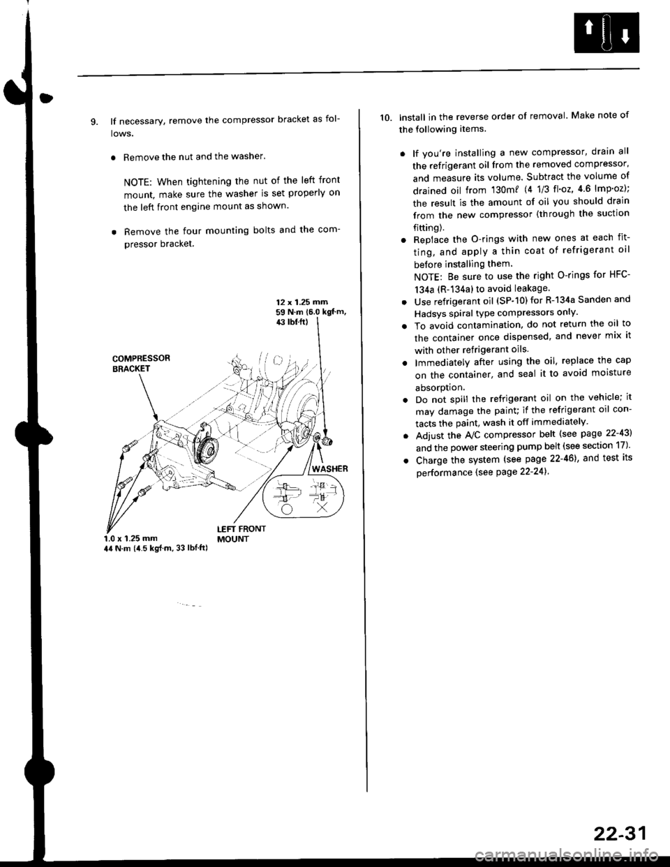
9. lf necessary, remove the compressor bracket as fol-
lows.
. Remove the nut and the washer.
NOTE: When tightening the nut of the left front
mount, make sure the washer is set properly on
the left front engine mount as shown.
. Remove the four mounting bolts and the com-
pressor bracket.
12 x 1.25 rrirn59 N.m 16.0 kgt'm,43 tbf.ft)
COMPRESSORBRACKET
WASHER
1.0 x 1.25 mm44 N.m (i1.5 kg{.m, 33 lbl.ft)
LEFT FRONTMOUNT
10. lnstall in the reverse order of removal. Make note of
the following items.
. lf you're installing a new compressor, drain all
the refrigerant oil from the removed compressor,
and measure its volume. Subtract the volume of
drained oil from '130m? 14 1/3 tl'o2,4 6 lmp'oz);
the result is the amount of oil you should drain
from the new compressor (through the suction
fifting).
. Replace the O-rings with new ones at each fit-
ting, and apply a thin coat of refrigerant oil
before installing them
NOTE: Be sure to use the right O-rings for HFC-
134a (R-134a) to avoid leakage
. Use refrigerant oil (SP-10) for R-134a Sanden and
Hadsys spiral type compressors only'
o To avoid contamination, do not return the oil to
the container once dispensed, and never mix it
with other refrigerant oils.
. lmmediatelY after using the oil, replace the cap
on the container, and seal it to avoid moisture
absorption.
. Do not spill the refrigerant oil on the vehicle; it
may damage the painu if the refrigerant oil con-
tacts the paint, wash it off immediately
. Adjust the Ay'C compressor belt (see page 22-43)
and the power steering pump belt (see section 17)'
. Charge the system (see page 22-46), and test its
oerformance (see Page 22-241
22-31
Page 1461 of 2189
Compressor (DENSO)
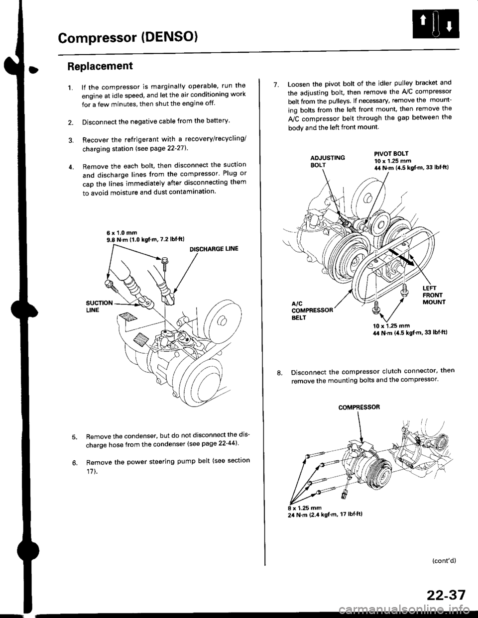
Replacement
1.lf the compressor is marginally operable, run the
engine at idle speed, and let the air conditioning work
for a few minutes, then shut the engine off
Disconnect the negative cable from the battery'
Recover the refrigerant with a recovery/recycling/
charging station lsee page 22-271
Remove the each bolt, then disconnect the suction
and discharge lines from the compressor' Plug or
cap the lines immediately after disconnecting them
to avoid moisture and dust contaminatlon.
6 x '1.0 mm9.8 N.m (1.0 kgf m,7.2 lbfft)
Remove the condenser, but do not disconnect the dis-
charge hose from the condenser (see page 22-441'
Remove the power steering pump belt (see sectron
17]-.
7. Loosen the pivot bolt of the idler pulley bracket and
the adjusting bolt. then remove the A,/C compressor
belt from the pulleys. lf necessary, remove the mount-
ing bolts from the left front mount. then remove the
fuC compressor belt through the gap between the
bodv and the left front mount.
'10 x 1,25 mm4,0 N.m (,1.5 kgf'm. 33 lbt ftl
Disconnect the compressor clutch connector, then
remove the mounting bolts and the compressor'
PIVOT BOLT10 x 1.25 mm4,1 N.m (4.5 kgt'm,33 lbfft)
COMPRESSOR
24 N.m (2.4 kgf m, 17 lbf ftl
(cont'd)
22-37
Page 1467 of 2189
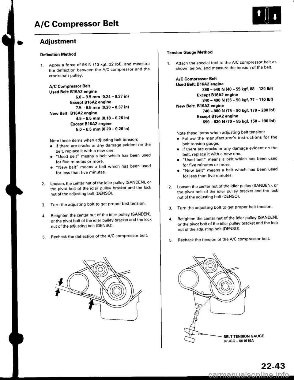
A/G GomPressor Belt
Adjustment
Detlection Method
'1. Apply a force of 98 N (10 kgf, 22 lbf), and measure
the deflection between the A,/C compressor and the
crankshaft PulleY
A/C ComPressor Belt
Used Belt: 816A2 engine
6.0 - 9.5 mm 10 2'l - 0.37 inl
Except 816A2 engine
7.5 - 9.5 mm (0.30 - 0.37 in)
New Belt: 816A2 engine
4.5- 6 5 mm (0.18-0.26 in)
Except 815A2 engine
5.0-5 5 mm (0.20-0.26 inl
Note these items when adjusting belt tens'on:
. lf there are cracks or any damage evident on the
belt, replace it with a new one.
. "Used belt" means a belt which has been used
for five minutes or more.
. "New belt" means a belt which has been used
tor less than five minutes.
2. Loosen, the center nut ofthe idler pulley (SANDEN), or
the pivot bolt of the idler pulley bracket and the lock
nut ofthe adjusting bolt (DENSO).
3. Turn the adjusting bolt to get proper belt tension'
4. Retighten the center nut of the idler pulley (SANDEN),
or the pivot bolt of the idler pulley bracket and the lock
nut of the adjusting bolt (DENSO).
5. Recheck the deflection of the A,/C compressor belt'
Tension Gauge Method
1. Attach the special tool to the IVC compressor belt as
shown below, and measure the tension of the belt
A/C Compressor Belt
Used Belt: 816A2 engine
390 - 540 N (40 - 55 kgf, 88 - 120 lbll
Except 816A2 engine
340 - 490 N (35 - 50 ksf, 77 - 110 lbfl
New Belt: B16A2 engine
?40 - 880 N {75 - 90 ksf' 170 - 200 lbf)
Except Bl642 engine
690 - 830 N (70 - 85 ksf, 150 - 190 lbf)
Note these items when adjusting belt tension:
. Follow the manufacturer's instructions for the
belt tension gauge.
. lf there are cracks or any damage evident on the
belt, rePlace it with a new one.
. "Used belt" means a belt which has been used
for five minutes or more.
. "New belt" means a belt which has been used
for less than five minutes
2 Loosen the center nut of the idler pulley (SANDEN)' or
the pivot bolt of the idler pulley bracket and the lock
nut of the adjusting bolt (DENSO).
3. Turn the adjusting bolt to get proper belt tension
4. Retighten the center nut of the idler pulley (SANDEN),
or the pivot bolt of the idler pulley bracket and the lock
nut of the adjusting bolt (DENSO)
5. Recheck the tension of the A/C compressor belt'
22-43