Page 273 of 2189

Component Locations
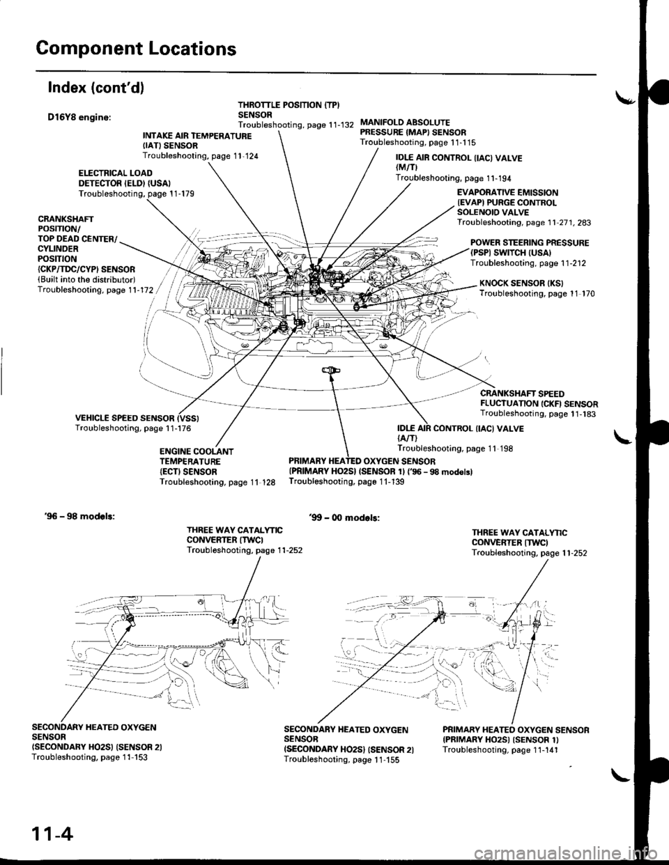
Index (cont'd)
D16Y8 enginc:
THROTTLE POSITION {TPISENSORTroubleshooting, page 1 1-132
ELECTRICAL LOADDETECTOR IELDI {USAI
INTAKE AIR TEMPERATUREIIATISENSORTroubleshooting, page 1 1,124
MANIFOLO ABSOLUTEPRESSURE {MAPI SENSORTroubleshooting, page 1 1-1 15
IDI.E{A/T)
IDI.E AIR CONTROL IIACI VALVElMtflTroubleshooting, page 1 1-194
Troubleshooting, page 1 1-179EVAPORATIVE EMISSIONIEVAPI PURGE CONTROLSOLENOIO VALVETroubleshooting, page 1 1 27 1. 283CRANKSHAFTPOSTTTON/TOP DEAD CENTER/CYLINDERPOStTtON
POWER STEERING PRESSURE(PSPI SWTTCH |USA)Troubleshooting, page 1 1-212{CKP/TI'C/CYPI SENSOR(Built into the distributor)Troubleshooting. page 1 1-172KNOCK SENSOR IKSITroubleshooting, page 11 170
CRANKSHAFT SPEEDFLUCTUANON ICKFI SENSORTroubleshooting, page 1 1,183
CONTROL {IACI VALVE
ENGINE COOLANTTEMPERATURE{ECTI SENSORTroubleshooting, page 11 128
Troubleshooting, page 11 198
PRIMARY HEATED OXYGEN SENSOR{PRIMARY HO2S} (SENSOR 1l {'96 - 98 modolslTroubleshooting, page 1 1-139
'9!t - 00 modols:'96 - 98 modols:
THREE WAY CATALYNCCONVERTER ITWCITroubl6shooting, page 1 1-252
THREE WAY CATALYNCCONVERTER ITWCITroubleshooting. page 1 1-252
SECONDARY HEATED OXYGENSENSOn(SECONDARY HO2SI (SENSOR 2ITroubleshooting, page 1 1-153
SECONDARY HEATED OXYGENSENSOBISECONDARY HO2S} ISENSOR 2ITroubloshooting, page 1 1-155
PRIMARY HEATEO OXYGEN SENSORIPRIMARY HO2SI ISENSOR 1ITroubleshooting, page 1 1-141
11-4
Page 274 of 2189

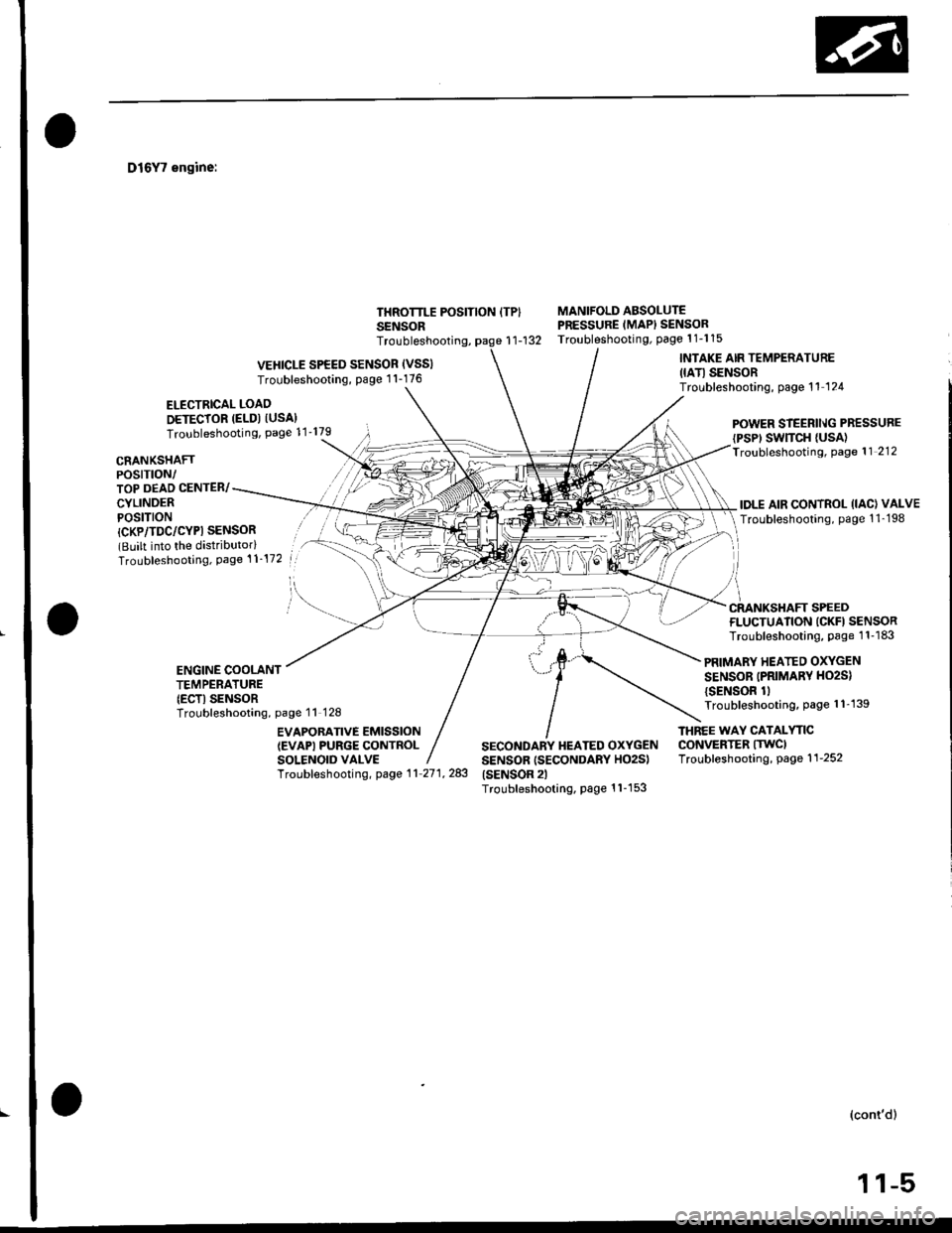
D16Y7 engine:
ELECTRICAL LOAO
DETECTOR (ELD) IUSA}Troubleshooting, Page 11'179
THROTTLE POSITION ITPISENSOR
MANIFOLD ABSOLUTEPRESSURE (MAPI SENSORTroubleshooting, Page 1 1-1 15r1-132
CRANKSHAFTPOSTTTON/TOP DEAD CENTER/
CYLINDERPOSITION
POWER STEERll\lG PRESSURE
{PSP' SWTTCH {USA)Troubleshooting, Page 11 212
IDLE AIR CONTROL (IAC) VALVE
Troubleshooting, page 1 1-198
Troubleshooting,
VEHICLE SPEED SENSOR (VSSI
Troubleshooting, Page 1 1-176
INTAKE AIR TEMPERATURE
IIATI SENSORTroubleshooting, page 11 124
l
/i
CRANKSHAFT SPEED
{CKP/TDC/CYPI SENSOR(Built into the distributorlTroubleshooting, Page 't 1-172
FLUCTUATION ICKFI SENSORTroubleshooting, Page 1 1-183
PRIMARY HEATED OXYGEN
SENSOR (PRIMARV HO2S)
{SENSOR 1lTroubleshooting, page 1 1'139
ENGINE COOLANTTEMPERATURE(ECTI SENSORTroubleshooting, page 11 128
EVAPOBATIVE EMISSION(EVAPI PURGE CONTROLSOLENOID VALVE
THNEE WAY CATALYTICCONVERTER ITWCITroubleshooting, page 1 1-252
Troubf eshooting, page 1 1 27 1, 283
SECONDARY HEATED OXYGENSENSOR (SECONDARY HO2S)(SENSOR 2lTroubleshooting, Page 1 1-1 53
(cont'd)
,l .ltr| | -r,
Page 275 of 2189
Component Locations
Index (cont'dl
Bl6A2 engine:
INTAKE AIR TEMPERATURE{IAT} SENSORTroubleshooting, page 1'1-125
MANIFOLO AESOLUTEPRESSURE IMAPI SENSORTroubleshooting. page 11-1 19IOLE AIR CONTROL {IAC) VALVETroubleshooting, page 1 1,196
ELECTRICAL LOADDETECTOR IELDI (USA)
Troubleshooting, page 1 1-180
THROTTLE POSITION ITPISENSORTroubleshooting, page 11-134
CRANKSHAfiPOStTtON/TOP DEAD CENTER/CYLINDERPOStTtON{CKP/TDC/CYPI SENSOR(Bualt into the distributor)Troubleshooting,page 11-174
POWER STEERING PRESSURE{PSPI SWTTCH (USA)
Troubleshooting, page 1 1-214
VEHICLE SPEED SENSOR {VSS}Troubleshooting, page 1 1-177
ENGINE
CRANKSHAFT SPEEDFLUCTUATION (CKFI SENSORTroubleshooting, page 11- t85TEMPERATUREIECTI SENSORTroubleshooting, page I 1-128
THREE WAY CATALYTICCONVERTER ITWC)Troubleshooting, page 1 1,252
S€CONOARY HEATED OXYGENsf rlsoR
sfCoNDARY HO2SI {SENSOR 2): ?shootrng, page 11 155
-6
PRIMARY HEATED OXYGEN SENSORIPRIMARY HO2S) ISENSOR 1ITroubleshooting, page 1 1-141
11
Page 309 of 2189
System Description
Electrical Connections ('99 - 00 Models except Dl6Y5 engine with M/Tl
(cont'd)
T:I
1
0
EVAP PURGE CONTROLSoLENOtOVAIVEc26 ECTECTSENSOR
D
EVAP COI{TROL CANISIE R
IATSENSOR
ta-t
c25 tAT
HO2S(sENSoFt
EVAP BYPASS SOI.ENOID VALVE
cl Po2s{tc"Eso! 87
)wEGF coNTRoL solENoro vaLvE'"c16PHO2S
vlsBr2VTEC SOLEr{O|D VATVE
H02SiSENSOR 2),wA23 SHO2S
VTECPFESSUFESWITCH
sEt{soR
-t,.1 f
I
BRAKE SWITCH
c7 sG1
SENSOB(Buln l oF
@E
lfil
*_r
/V | GAUGE
* lassEMBLIIl-
SPEEOSENSOR
tr
D5VBSOLo4tND A14
N DTI
NC DTOSPEEDSENSOR
LS+ Bl7UNEAR SOLENOID VALVET'I AT?04LS- a3
LOCIPr. l03alP03LCA 01P CONTBOISOIENOiDVALVE BLCB 03IOI{IROL SOLENOID VAIV€ A
SHIFI COTITROL SOLENOID VALVE BSHE D2
POStTtON
t----
I
To IIIT!FLOCK CONTROL UNIT
--t
L
l-
I
I
11-40
-.._.._.._.._l
,'-J
Page 313 of 2189
System Description
Electrical Gonnections ('99 - 00 Models except Dl6yS engine with M/T)(cont'd)
cad__J
neozvef- -l
q30
1""
h/wFDlt+l-lvss
EVAP CONTROLCANISTEF VENTSHUI VALVE
l,,"
I
Fl
TI
| "u,LB|.X'--Jf-ll
PsP swrcH'
VTECsoLEt{otoVALVE
cliaBLTC.YEL ----J----]
neo,"yrr.'--{l- ---5 |EVAP PUBGECONTROLSOLENOIDVALVE
clat
11-44
Page 348 of 2189
c130
I10
l112131,4t5ta11t8t9
ct3r
1lz3lt/X61789to
cr34 tEcM/PCM-C)cr35 lPCM-Dr:cr35lPcl|.D,€
ca32
lr 2 3.1
IiGTNiBN Ill
l5l-wxr,nol]ll:a BLX vHI I
NOTE; . Different wires with the same color have been given a number suffix to distinguish them (for example, YEUBLK1
and YEUBLK, are not the samel.
O: Related to Fuel and Emissions Svstem.- Connector with male terminals (double outline): View from terminal side
- Connector with female terminals (single outline): View from wire side
lrl2l
lll* -_-l
tn Bs I
c1a
lr 2l
f.fil
,bl onrrwlrl.lftlBLrwHri-Flirx,lvHJ l]-l
c,|52 tEcM/PCM-Al
\-a
't/3l-1.51
/tgto 'lt12l3
2at6IE e t|0111'12ItItIt[l
11-79
Page 350 of 2189

Troubleshooting
Troubleshooting Procedures
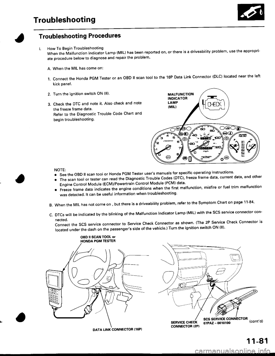
How To Begin Troubleshooting
When the Malfunction Indicator Lamp (MlL) has been reported on, or there is a driveability problem, use the appropr'-
ate orocedure below to diagnose and repair the problem'
A. When the MIL has come on:
,1. connect the Honda PGM Tester or an oBD ll scan tool to the 16P Data Link connector (DLC) located near the left
kick panel.
2. Turn the ignition switch ON (ll)
3. Check the DTC and note it. Also check and note
the freeze trame data
Refer to the Diagnostic Trouble Code Chart and
begin troubleshooting.
NOTE:
.SeetheoBD||scantoolorHondaPGMTesteruser,smanua|sforspecificoperatinginstructions..
.Thescantoo|oltestercanreadtheDiagnosticTroub|ecodes(DTc},freezeframedata,currentdata,andother
Engine Control Module (ECM)/Powertrain Control Module (PCM) data'
oFreezeframedataindicatestheengineconditionswhenthefirstma|function,misfireorfue|trimma|function
was detected. lt can be useful information when troubleshooting'
B. When the MIL has not come on , out there is a d riveability problem, refer to the Symptom Chart on page 1 1-84'
c.DTcswi|lbeindicatedbytheb|inkingoftheMa|function|ndicatorLamp(M|L)withthescsserviceconnectorcon.
nected.
Connect the SCS service connector to Service Check Connector as shown (The 2P Service Check Connector is
|ocatedunderthedashonthepassenger,ssideofthevehic|e')TurntheignitionswitchoN{||)'
OBO ll SCAN TOOL olHONOA PGM TESTER
SERVICE CHECKCONNECTOR I2P)
scs sERvlcE(cont'd)
MALFUNCTIONINDICATORLAMP
DATA LINK CONNECTOR Il6PI
07PAZ - (x)l0100
11-81
Page 355 of 2189

Troubleshooting
Troubleshooting Procedures (cont,dl
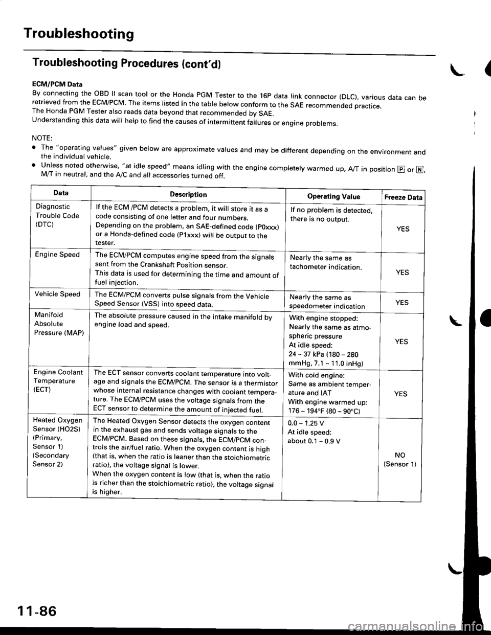
ECM/PCM Data
By connecting the OBD ll scan tool or the Honda pGM Tester to the l6p data link connector (DLC), various data can beretrieved from the EcM/PcM. The items Iisted in the table below conform to the sAE recommended practice.The Honda PGM Tester also reads data beyond that recommended bv SAE.understanding this data wil help to find the causes of intermittent fairures or engine probrems,
NOTE:
' The "operating values" given below are approximate values and may be different depending on the environment andthe individual vehicle.. Unless noted otherwise, "at idle speed,, means idling with the engine completely warmed up, Ay'T in position @ or E],M/T in neutral, and the Ay'C and all accessories turned off.
(
DataDescriptionOperating ValueFreeze Data
Diagnostic
Trouble Code(DTC)
lf the ECM /PCM detects a problem, it will store it as acode consisting of one letter and four numbers.Depending on the problem, an SAE-defined code (poxxx)or a Honda-defined code (Plxxx) will be outDut to therester.
lf no problem is detected,
there is no output.
YES
Engine SpeedThe ECM/PCM computes engine speed from the signalssent from the Crankshaft Position sensor.This data is used for determining the time and amount offuel injection,
Nearly the same as
tachometer indication.YES
Vehicle SpeedThe ECM/PCM converts pulse signals from the VehicleSpeed Sensor (VSS) into speed data.Nearly the same as
speedometer indicationYES
Manifold
Absolute
Pressure {MAP)
The absolute pressure caused in the intake manifold bvengine load and speed.With engine stopped:
Nearly the same as atmo-
spheflc pressure
At idle speed:
24 - 31 kPa (180 - 280
mmHg, 7.1 - 11.0 inHg)
YES
Engine Coolant
Temperature
(ECT)
The ECT sensor converts coolant temperature into volt_age and signals the ECM/PCM. The sensor is a thermistorwhose internal resistance changes with coolant temDera_ture. The ECM/PCM uses the voltage signals from theECT sensor to determine the amount of iniected fuel.
With cold engine:
Same as ambient temper,
ature and IAT
With engine warmed up:
176 - 194.F (80 - 90.C)
YES
Heated Oxygen
Sensor {HO2S)(Primary,
Sensor 1)(Secondary
Sensor 2)
The Heated Oxygen Sensor detects the oxygen contentin the exhaust gas and sends voltage signals to theECI\4/PCM. Based on these signats, the ECM/pCM con_trols the airlfuel ratio. When the oxygen content is high(that is, when the ratio is leaner than the stoichiometricratio), the voltage signal is lower.When the oxygen content is low (that is, when the ratiois richer than the stoichiometric ratio), the voltage signalis higher.
0.0 - 1.25 V
At idle speed:
about 0.1 - 0.9 V
NO(Sensor 1)
1 1-86