1999 HONDA CIVIC pan
[x] Cancel search: panPage 352 of 2189

lf the inspection for a particular code requires voltage or resistance checks at the ECM/PCM connectors, remove the right
kick panel. Pull the carpet back to expose the ECM/PCM. Remove the ABS control unit if so equipped. unbolt the EcM/
PCM bolt. Turn the ignition switch oFF, and connect the backprobe sets and a digital multimeter as described below
check the system according to the procedure described for the appropriate code(s) listed on the following pages'
The illustrationshows '96 - '98 models.
How to Use lhe Backprobe Sets
connect the backprobe adapters to the stacking patch cords, and connect the cords to a multimeter. using the wire insula-
tion as a guide for the contoured trp of the backprobe adapter. gently slide the tip into the connector from the wire side
until it comes in contact with terminal end of the wire'
BackProbe
BACKPROEE SET
07SAZ - 001000A lTwo
DIGITAL MULTIMETER(Commercially avail.bleI orKs - AHM - 32 - oo3 (cont'd)
KICK PANEL
1 1-83
Page 395 of 2189
PGM-FI System
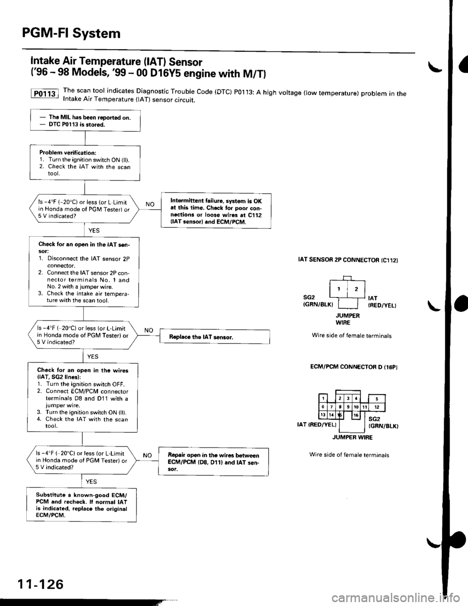
Intake Air Temperature (lAT) Sensor
('96 - 98 Models,'99 - 00 D16Y5 engine with M/Tl
11-126
The scan tool indicates Diagnostic Trouble Code (DTC) POl13: A high voltage flow temperature) problem in theIntake Air Temperature (lAT) sensor circuit,
taT sENsoR 2P CONNECTOn (Cl12l
I' jrl
SG2 '---.]__+ tAT(GRN/BLKI I I IRED/YEL}
JUMPERWIRE
Wire side of female terminals
ECM/PCM CONNECTOR D (16PI
IAT IRED/YEL)sG2(GRN/BLK)
JUMPER WIRE
Wire side of female terminals
The MIL has been reported on.DTC P0113 b sto.6d.
Problem veritication:1. Turn the ignition switch ON (ll).2. Check the IAT with the scantool.
Intermittent tailuJe, systom is OKat this time, Check to. poor con-nections or loose wir.s at C112{lAT senso.l .nd ECM/PCM,
ls -4'F 1-20"C) or less (or L Limitin Honda mode of PGNI Tester) or5 V indicated?
Check for an open in the IAT sen-sol:1. Disconnect the IAT sensor 2pconnector,2. Connect the IAT sensor 2P con-nector terminals No, 1 andNo.2 with a jumper wjre.3. Check the intake air tempera,ture with the scan tool.
ls -4"F ( 20'C) or less (or L-Limitin Honda mode of PGM Tester) or5 V indicated?Repbce the IAT sensor.
Check tor an open in th6 wires{lAT. SGzline!):1. Turn the ignition switch OFF.2. Connect ECM/PCM connectorterminals D8 and D11 with a
3. Turn the ignition switch ON (ll).4. Check the IAT with the scantool.
ls -4"F ( 20'C) or less (or L-Limitio Honda mode ol PGM Tester) or5 V indicated?
R€p6ir opan in the wiro! hweenEC-M/PCM lD8. 011l and IAT sen-
Substitute a known-good ECM/PCM end recheck. lf normal IATis indic.ted, replace the originalECM/PCM.
Page 396 of 2189
L
I
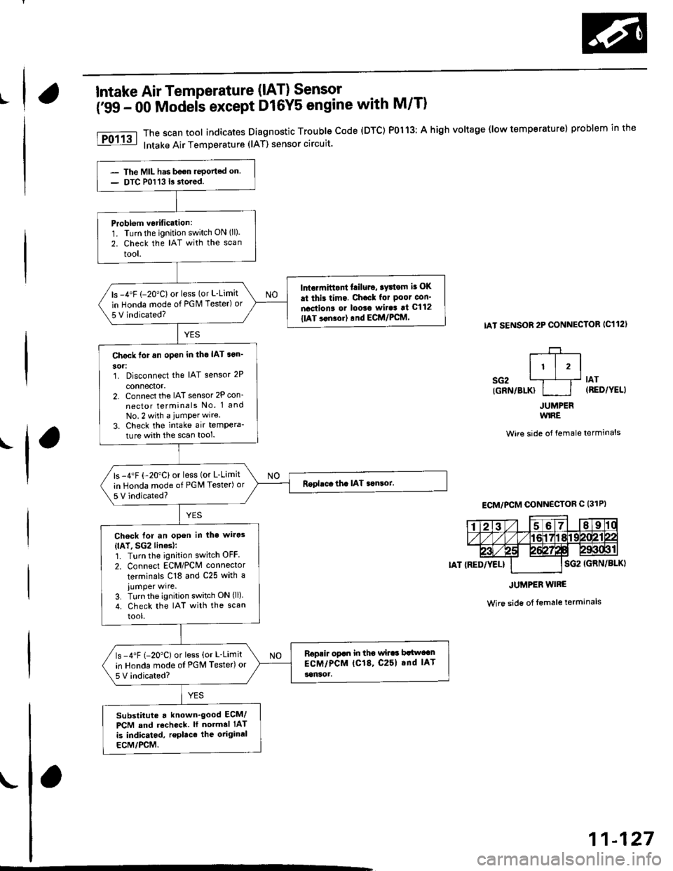
Intake Air Temperature (lAT) Sensor
('99 - 00 Modeis except D16Y5 engine with M/Tl
The scan tool indicates Diagnostic Trouble code (DTC) P0113: A high voltage (low temperature) problem in the
Intake Air Temperature (lAT) sensor circuit.
IAT SENSOR 2P CONNECTOB IC112'
r-+-r
It l,lsG2 L1__f lAr
IGRN/BLK} I I (RED/YELI
JUMPERWIRE
Wire side of female terminals
Wire side of lemale terminals
The MIL has be€n rePorted on.
DTC P0113 i3 stored.
Probl€m vetification:1. Turn the ignition switch ON (ll).
2. Check the IAT with the scan
tool.
Intormittont f.iluro, tyrtom i. OK
.t thi! tim.. Chocl for Poor con'
nactions or looso wit6 !t C112
tlAT ..n!or) rnd ECM/PCftl,
ls -4"F (-20"C) or less (or L-Limit
in Honda mode of PGM Tester) or
5 V indicated?
Check tor an open in tho IAT son'
304:1. Disconnect the IAT sensor 2P
connector,2. Connect the IAT sensor 2P con_
nector terminals No. 1 and
No.2 with a jumPerwire.
3. Check the intake air tempera-
ture with the scan tool.
ls -4"F {-20"C) or less (or L-Limit
in Honda mode of PGM Tester) or
5 V indicated?
Check lor an open in iho wirg3
{lAT, SG2 linesl;1. Turn the ignition switch OFF
2. Connect ECM/PCM connector
terminals C18 and C25 with a
iumper wire.3. Turn the ignition switch ON (ll)
4. check the IAT with the scan
tool.
Roprir opan in tho wilaa brlwocn
ECM/PCM (C18, C25l .nd IAT
!on30r.
ls -4"F (-20"C) or less (or L-Limit
in Honda mode oI PGM Testerlor
5V indicated?
substituts a known'good ECM/
PCM and recheck. ll normal IAT
is indicated, replace the otiginal
ECM/PCM.
ECM/PCM CONNECTOR C (31PI
JUMPER WIRE
11-127
Page 403 of 2189
PGM-FI System
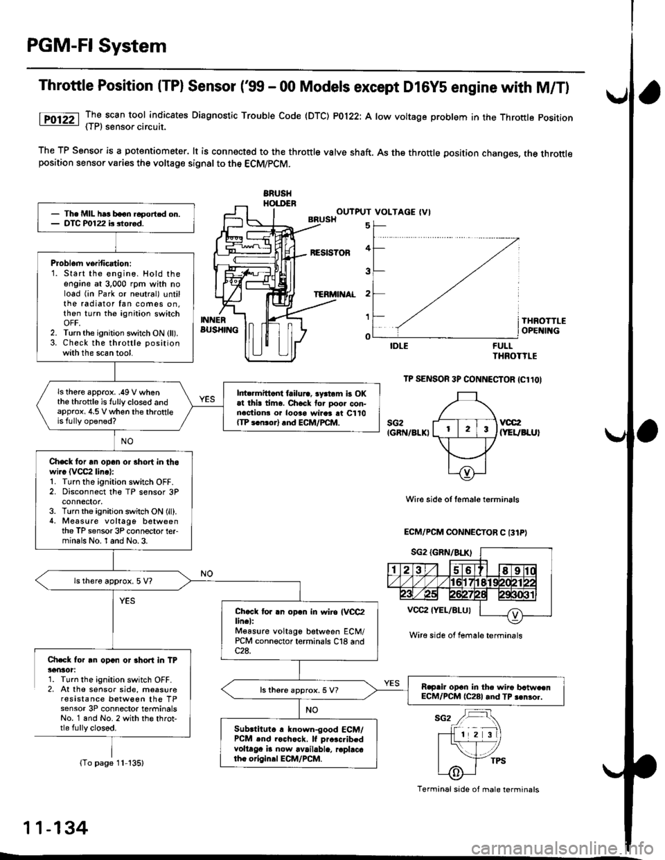
Throttle Position (TPl Sensor ('99 - 00 Models except D16Y5 engine with M/T)
lTO12Z _TI scan tool indicates Diaqnosttc Trouble Code (DTC) P0122: A low voltage problem in the Throttle position- { | r, sensoa crrcurl.
The TP Sensor is a potantiometer. lt is connected to the throttle valve shaft. As the throttle position changes, the throttleposition sensor varies the voltage signal to the ECM/PCM.
ERUSHHOI.DENOUTPUT VOLTAGE (VIBRUSH
BESIS?OF
TERi'I AL
5
4
3
2
1
o
INNERBUS}IINGTHROTTLEOPE II{G
FULLTHROTTLE
TP SENSOR 3P CONNECTOR {Cl1OI
sG2IGRN/8LKIvcc2(YEUBLUI
Wire side of temale terminals
ECM/PCM OONNECTOR C 131P)
Ch.Gk for rn opan or 3hort in TP36nlot:1. Turn the ignition switch OFF.2, At the sensor side, moasureresistance between the TPsensor 3P connector terminalsNo. 1 and No. 2 with th€ throt,tle fully closed.
(To page 11-135)
- Th. MIL har boon.6portcd on.- DTC P0122 b siored.
Problem verification:1. Start the engine, Hold theengine at 3,000 rpm with noload (in Park or neutral) untilthe radiator fan comes on.then turn the ignition switchOFF,2. Turn the ignition switch ON (ll).3. Check the throttle positionwith the scan tool.
ls there approx. .49 V whenthe throttle is fully clos€d andapprox, 4.5 V when the throttleis fully opened?
l||t rmittont failura, lyrtom b OKat thi! tima. Chock tor poor con-nactionr o. looao wires rt C110{TP 3.n!or} rnd ECM/PCM.
Check for an opan or 3hort in thowi.c (VCC2 linc):1. Turn the ignition switch OFF.2. Disconnect the TP sensor 3Pconnector,3. Turn the ignition switch ON (ll).4. Measure voltago betweenthe TP sensor 3P connector terminals No. 1 and No.3.
ls thero approx. 5 V?
Chccl tor .n opln in wiro IVCC2lin€l:Mgasure voltago between ECM/PCM connector terminals C18 and
R.prir opcn in the wiro bctw.enECM/PCM (C281 and TP 3€nror.ls there approx. 5 V?
Subrtituto r known-good ECM/PCM .nd rochcck. lf pro.c.ibedvoltaga i! now available, roplacotho origin.l ECM/PCM.
Wire side ol female terminrls
Terminal side of male terminals
11-134
L
Page 405 of 2189
PGM-FI System
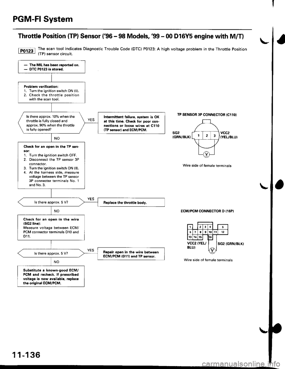
Throttle Position (TP) Sensor (€6 - 98 Models, 39 - 00 D16Y5 engine with M/T)
The scan tool indicates Diagnostic Trouble Code (DTC) P0123: A high voltage problem in the Throttle Position(TP) sensor circuit.
TP SENSOR 3P CONNECTOR IC1lOI
sG2IGRN/BLKIvcc2{YEL/BLUI
Wire side of female terminals
ECM/PCM CONNECTOR D (16P)
SG2 (GRN/BLKI
Wire side of female terminals
1 1-136
The MIL has been reportod on.DTC P0123 is sto.ed.
Problom veritication:1. Turn the ignition switch ON {ll).2. Check the throttle positionwith the scan tool.
ls there approx. 10% when thethrottle is fully closed andapprox. 90o/o when the throttleis lully opened?
Intermittont tailuro, system is OKat thb timo, Check for ooor con-nociion3 or loos6 wiros at C110ffP s€nsor) and ECM/PCM.
Chgck to. an opan in the TP son-sot:1. Turn the ignition switch OFF.2. Disconnect the TP sensor 3Pconnector.3. Turn the ignition switch ON (ll).
4. At the harness side, measurevoltage between tho TP sensor3P connecter terminals No, 1and No.3.
ls there approx.5 V?
Ch.ck tor .n open in the wira(SG2 linel:Measure voltage between ECM/PCM connector terminals D10 andD11.
Repair op6n in the wire betwoenECM/PCM (D11) rnd TP s6nsor.ls there approx. 5 V?
Substitute a known-good ECM/PCM snd rech.ck. lf pra3cribed
voltago is now available, replscetho original ECM/PCM,
Page 424 of 2189
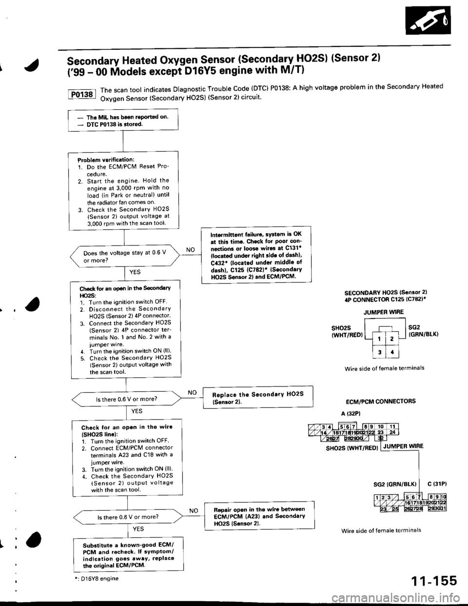
Secondary Heated Oxygen Sensor (SecondarytlO2S) (Sensor 2l
('99 - 00 lilodels except DtGYS engine with M/T)
The scan tool indicates Diagnostic Trouble code (DTC) P0138: A high voltage problem in the secondary Heated
Oxygen Sensor (Secondary H02S) (Sensor 2) circuit.
SECONDARY HO2S {S€nsot 2}
4P CONNECTOR Cl25 lc782l'
JUMPER WIRE
Ir
sH02s(WHT/RED)sG2{GRN/BLKI
Wire side of female termanals
ECM/PCM CONNECTORS
A (32P1
Wire side ot female termlnals
gs92g 111yp17p5py | .lutuPea wtne
- The MIL has beon reportod on.- DTC m138 is.tored.
Ploblem vorification:1. Do the ECM/PCN4 Reset Pro-
cedure.2. Start the engine Hold the
engine at 3,000 rpm with no
load (in Park or neutral) until
the radiator{an comes on
3. Check the SecondarY H02S(Sensor 2) output voltage at
3,000 rpm with the scan tool
lntormittont failuio, sYstom b OK
st thir timo. Check for Poor con_
nections ot loo39 wiJo3 af Cl3lr(located under right ride ot desh),
C432' (locatod undot middle of
dashl, Cl25 {C782lr (Secondaiy
HO2S Son3or 2l and ECM/PCM.
Does the voltage stay at 0 6 V
or more?
Ct€d( tor an opan in the Secondary
l|o2s:1. Turn the ignition switch OFF
2. Disconnect the SecondarY
HO2S (Sensor 2) 4P connector.
3. Connect the Secondary HO2S(Sensor 2) 4P conneclor ter_
minals No. 1 and No.2 with a
iumper wire.4. Turn the ignition switch ON (ll)
5. Check the SecondarY HO2S
lSensor 2) outptlt voltage with
the scan tool,
lsthere 0.6 V or more?
Check lor an open in the wiro(SHO2S line):1. Turn the ignition switch OFF.
2. Connect ECM/PCM connector
terminals A23 and C18 with ajumper wrre,
3. Turn the ignition switch ON (ll).
4. Check the SecondarY HO2S
{Sensor 2) outPut vo ltage
with the scan tool.
Repair opon in tho wire betwecn
ECM/PCM (A23) and SocondarY
HO2S {Sansor 2).ls there 0.6 V or more?
Substitut€ a known'good ECM/
PCM and recheck. It symptom/indication goes awey, JePlaco
the otiginel ECM/PCM
*i 016Y8 engine1 1-155
Page 427 of 2189

PGM-FI System
a
a
Heated Oxygen Sensor (HO2S) Heater
('96 - 98 Models,'99 - 00 D16Y5 engine with M/T) (cont'dl
PRIMARY HO2S {SENSOR 1I 4P CONNECTOR{c1231SECONDARY HO2S {SENSOR 2} 4PcoNNECTOR 1C125)r
r-l --'1
ll i2l
f;T;ttcl|BLK/ &)YELI Y
Wire side of fomale lerminals
SECONDARY HO2SISENSOR 2) 4P CONNECTOR{c78ilf
IBLK/WHT)
Wire side of lemale terminals
(From page 11-157)
Wire sid€ ot temale terminals
SO2HTC(BLK/WHTI* PO2SHTC{BLK/WHTI
*: P0141*+: Dl6Y8 engine
11-158
(From page 11-157)
Check tor an op6n or 3hoft in thewire {lGl lin6):Measure voltage between theHO2S 4P connector terminals No.3(D16Y8 engine: No. 4) and bodyground.- Repair open or shon in thewire between Primary HO2Slson.or 1), {No. 15 ALTERNA-TOR SP SENSORI (7.5 Al fuseand Secondary HO2S, Sonsol2t,.- Replace the No. 15 ALTERNA-TOR SP SENSOR 17.5 A) tuse.Check for an open in the wireIPO2SHTC, SO2SHTC' linel:1. Turn the ignition switch OFF.2. Reconnect the HO2S 4P con-nector.3. Disconnect the ECM/PCM con-nector A (32P).
4. Turn the ignition switch ON (ll).
5. Measure voltage between theECM,/PCM connector terminals46 and 410 {A5 and A10)*.
Ropail opan in the wire b€twoenECM/PCM lA6, A5l* and HO2S{Primary, Secondary+1.
ls there 0.1 V or less?
Substitute a known-good ECM/PCM and recheck. ll symptom/indication goes awry, repbcetho origin.l ECM/PCM.
ECM/PCM CONNECTOR A I32P)
so2sHrc ItBLK/WH0.J
pozsxtc E/
IBI-K/WHTI ^,-----{v}-|.=,|I
PG1IBLK}3u I JsTgT roll12r3t5t6Ittar920z2l 2321
25272A2i3o
Check tor a short in the wire{PO2SHTC. SO2SHTC* line):'1. Turn the ignition switch OFF.2. Disconnect the ECM/PCM con-nector A (32P1.
3. Check for continuity betweenthe ECM/PCM connector termi-nal 46 (A5)* and body ground.
Repair short in thg wire betwe€nECM/PCM lA6, A5*l .nd HO2S(P.im.ry, Socondary*).
Substitute a known-good ECM/PCM and recheck. It symptom/indicetion goes away, rophcethe original ECM/PCM.
Page 450 of 2189
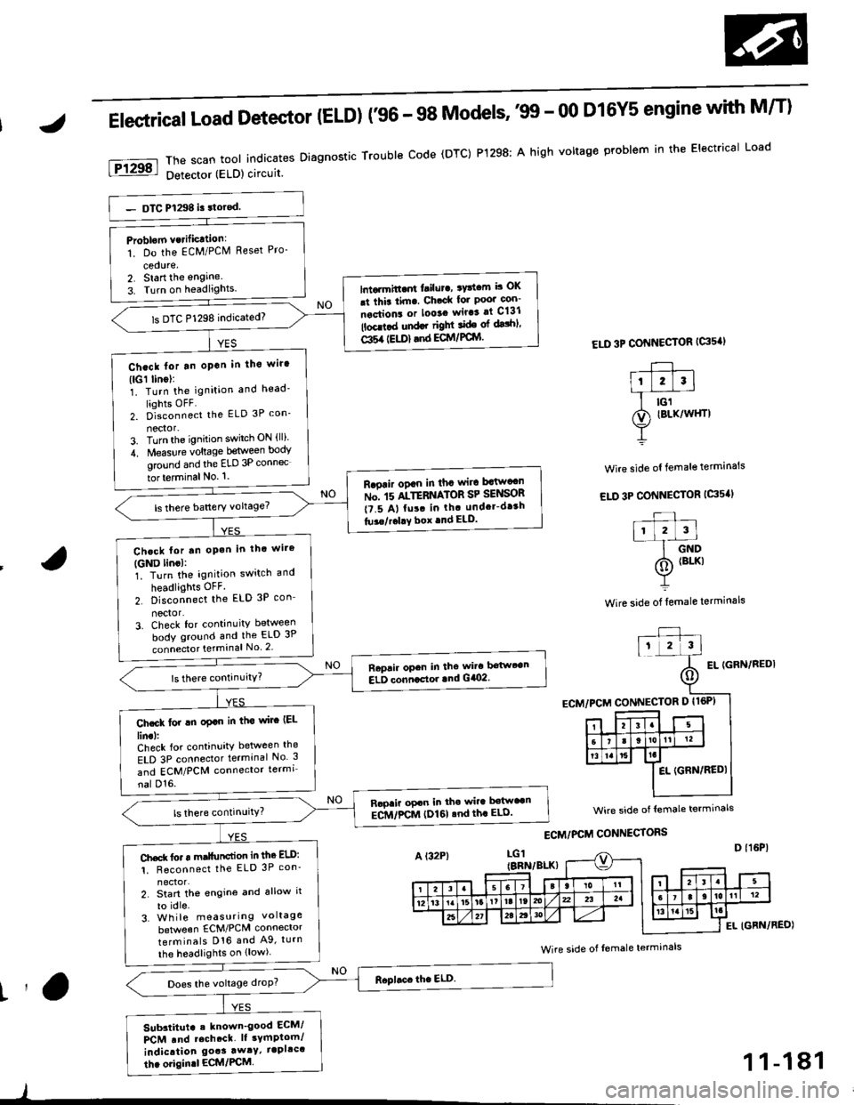
Elestrical Load Detector (ELD) f96 - 98 Models''99 - 00 D16Y5 engine with M/T)
ThescantoolindicatesDiagnosticTroubleCode(DTC)P1298:AhighvoltageproblemintheElectricalLoad
Detector (ELD) circuit
ELD 3P CONNECTOR {G's'I
Wire side ol female terminals
EL IGFN/REDI
Problom vcrificttion:
1. Do the EcM/PClVl Reset Pro-
cedure,2. Start the engine.
3. Turn on headlights.lntarmitt..rt l.ilur., ryttcm b OK
.t thia tim. Ch.ck lor Poo' con-
nections or looaa wir.3 at C131
lbcd.d und.r right ide ol dalhl'
Gl5a {EU)} .nd ECM/PCIYI
ls DTC P1298 indicated)
Ch.ck lor tn oPan in tho wir'
(lGl linol:1. Turn the ignition and head'
liohts OFF2. D]""onn""t the ELD 3P con_
nector-3. Turn the ignition switch ON {ll)'
4. Measure voltage between body
ground and the ELD 3P connec
tor terminal No. '1.
R.oair ogan in tha wira Mw"n
ru". rs ltTEnrlton SP SelSOn
t?.5 A, fu!. in th. undcr-dr3h
tu3e/r.l!Y box .nd ELD.
Chcck lor tn oP.h in thc wire
{GND lincl:1. Turn the ignition switch and
headlights OFF.
2. Disconnect the ELD 3P con_
nector'3. Check for continuity between
body ground and the ELD 3P
connecto. terminal No 2
Raprir opcn in the wira bstwt€n
ELD conncctor lnd G/O2.
Ch.ck lor !n oplo in tha wirc IEL
lin.l:Check for continuity between the
ELD 3P connector terminal No 3
and ECM/PCM connector termi
nal D'16.
Rapaii opcn in the wira b€tw"n
ECM/FCM (I)161 .nd th. ELD'
Ch.d( fo. r m.llunction in thc ELD:
1. Reconnect the ELD 3P con'
2. Start th€ engine and allow it
to idle.3. Wh ile measuring voltage
beNveen ECM/PCM connector
terminals D16 and A9, turn
the headlights on {low).
Does the voltage droP?
Sub3titut. . known_good ECM/
PCM .nd rcch.ct. lt sYmptom/
indication goas away/ iapllc'
thc origin.l ECM/PCM
wire side of lemale termrnals
Wire side of Iemale terminals
t'a
)
1 1-181