Page 1028 of 2189

Transmission
Gooler Flushing
@ To prevent iniury to face and eyes, alwayswear safety glasses or a tace shield when using thetransmission flusher.
NOTE: This procedure should be performed before rein-stalling the transmission.
'1. Check the tools and hoses for wear and cracks before
using. lf wear or cracks are found, reDlace the hoses
before using.
4.
Using the measuring cup. fill the tank with 2,1 ounces(approximately 2/3 full) of biodegradable flushingfluid (J35944 - 20). Do not substitute with any otherfluid. Follow the handling procedure on the fluidcontatner.
Secure the flusher filler cap, and pressurize the tankwith compressed air to between 5S0 - 829 kpa (5.6 -
8.45 kgf/cm'�, 80 - 120 psi).
NOTE: The air line should be equipped with a watertrap to ensure a dry air system,
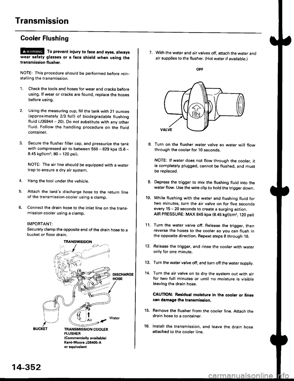
Hang the tool under the vehicle.
Attach the tank's discharge hose to the return lineoi the transmission cooler using a clamp.
Connect the drain hose to the inlet line on the trans-mission cooler using a clamp.
IMPORTANT:
Securely clamp the opposite end ofthe drain hose to abucket or floor drain,
t
TRANSMISSION COOLERFLUSHER{Commercially available)Kent-Moore J384O5-Aor oouivalent
TRANSMISSION
14-352
7. With the water and air valves off, attach the water andair supplies to the flusher. (Hot water if available.)
8. Turn on the flusher water valve so water will flowthrough the cooler for 10 seconds.
NOTE: lf water does not flow through the cooler, itis completely plugged, cannot be flushed, and mustbe replsced.
9. Depress the trigger to mix the flushing fluid into thewater flow. Use the wire clip to hold the trigger down.
'10. While flushing with the water and flushing fluid fortwo minutes. turn the air valve on for five secondsevery 15 - 20 seconds to create a surging action.AIR PRESSURE: MAX 845 kpa (8.45 kgflcmr, 120 psi)
11. Turn the water valve off. Release the trigger, thenreverse the hoses to the cooler so you can flush inthe opposite direction. Repeat steps 8 through 10.
12. Release the trigger. and rinse the cooler with wateronly for one minute.
13, Turn the water valve off, and turn off the water supply.
'14. Turn the air valve on to dry the system out with airfor two full minutes or until no moisture is visibleleaving the drain hose.
CAUTION: Rosidual mobturo in the qooler or linescln damage the transmission,
15. Remove the flusher from the cooler line. Attach thedrain hose to a container.
16. Install the transmission. and leave the drain hoseattached to the cooler line.
Page 1029 of 2189
![HONDA CIVIC 1999 6.G Workshop Manual l.
17.Make sure the transmission is in the E] position.
Fill the transmission with cvT Fluid, and run the
engine for 30 seconds or until approximately 0 95 {
(1.0 US qt.,0.8 lmp qt.) is discharged.
Re HONDA CIVIC 1999 6.G Workshop Manual l.
17.Make sure the transmission is in the E] position.
Fill the transmission with cvT Fluid, and run the
engine for 30 seconds or until approximately 0 95 {
(1.0 US qt.,0.8 lmp qt.) is discharged.
Re](/manual-img/13/6068/w960_6068-1028.png)
l.
17.Make sure the transmission is in the E] position.
Fill the transmission with cvT Fluid, and run the
engine for 30 seconds or until approximately 0 95 {
(1.0 US qt.,0.8 lmp qt.) is discharged.
Remove the drain hose, and reconnect the cooler
return hose to the transmission (see page 14-355)
Refill the transmission with CVT Fluid to the proper
level (see page 14-299).
18.
'19.
.l ,
TOOL MAINTENANCE
1. Empty and rinse after each use. Fill the can with water
and pressurize the can. Flush the discharge line to
ensure that the unit is clean.
2, lf discharge liquid does not foam, the orifice may be
blocked.
3. To clean, disconnect the plumbing from the tank at
the large couPling nut.
FILTER
\
\- 0--D
i
I
O.RING
Remove the in-line tilter from the discharge side and
clean if necessary'
The fluid orifice is located behind the filter. Clean it
with the pick stored in the bottom of the tank han-
dle. or blow it clean with air. Securely reassemble
all parts.
COUPLINGNUT
II
-@q
\ORIFICE
FILLER CAP
14-353
Page 1036 of 2189
Driveshafts
Inspection
Driveshaft Boot
Check the boots on the driveshaft for cracks, damage,
leaking grease and loose boot bands. lf any damage is
found, replace the boot and boot bands,
Loose Splines
Turn the driveshaft by hand and make sure the splines
and joint are not excessively loose. lf any damage is
found, replace the inboard joint.
Twisied or Cracked
Make sure the driveshaft is not twisted or cracked.
Reolace it if necessarv.
DRIVESHAFT
BOOT BANDS
1.
Removal
Loosen the wheel nuts slightly.
Raise the front of the vehicle, and support it with
safety stands in the proper locations (see section 'l).
Remove the wheel nuts and front wheels.
Drain the transmission fluid (see section 13 or 14).
Raise the locking tab on the spindle nut, then
remove the nut.
Remove the selJ-locking nut and flange bolts.
FLANGE BOLT10 x 1.25 mm
(cont'd)
16-3
1.
Page 1053 of 2189
Intermediate Shaft
Removal
Drain the transmission oil or fluid {see section 13 or
r 4).
Remove the left driveshaft (see page 16-3).
Remove the three dowel bolts.
OOWEL BOLTS'10 x 1.25 mm
Remove the intermediate shaft from the differential.
CAUTION: Hold the intermsdiate shaft horizontal
until it is clear of lhe dilterential to prevent damage
to the differential oil seal.
'1.
2.
3.
INTERMEDIATE SHAFT
16-20
Disassembly
NOTE: Be careful not to damage the metal rings on theintermediate shaft during disassembly.
1. Remove the set ring.
2. Remove the intermediate shaft outer seal from theDeaflng suppon.
3. Remove the external circlip,
Page 1085 of 2189
Pump outlet line(high pressure,
/
Pump inlet Iine(low-pressure)
Replace the housing O-rings
lf the housing still leaks, rePlace
the pumP.
Reservoir is overfilledPull off the hose and drain the
reservoit to the Proper level.
Air leak in suction side ofthe sys'
tem (reservoir, inlet hose, tront
pump seal).
Tighten the fifting. lI it's still leak-
ing, replace the O-ring or feed line.Leaking at the threaded fitting
Leaking at the swagged joint.
Leaking because ol damage, dete_
rioration, or imProPer assemblY.Reolace or rePair as necessarY.
tJ
17-29
Page 1098 of 2189

Power Steering Pump
Disassembly (cont'dl
2.
't.Drain the fluid from the pump.
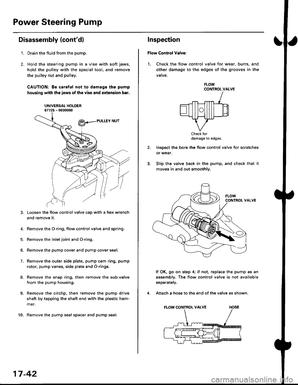
Hold the steering pump in a vise with soft jaws,
hold the pulley with the special tool, and remove
the pulley nut and pulley.
CAUTION: Be careful not to damage the pump
housing with the iaws of the vise and extension bar.
UNIVERSAL HOLDER
Loosen the flow control valve cap with a hex wrench
and remove it.
4. Remove the O-ring, flow control valve and spring.
5. Remove the inlet joint and O-ring.
6. Remove the pump cover and pump cover seal.
7. Remove the outer side plate, pump cam ring, pump
rotor, pump vanes, side plate and O-rings.
8. Remove the snap ring, then remove the sub-valve
from the pump housing.
9. Remove the circlip, then remove the pump drive
shaft by tapping the shaft end with the plastic ham-
mer.
10. Remove the pump seal spacer and pump seal.
17-42
Inspection
Flow Control Valve:
1. Check the tlow control valve for wear. burrs, and
other damage to the edges of the grooves in the
vatve,
FLOWCONTROL VALVE
Check fordamage to edges.
Inspect the bore the flow control valve for scratches
or wear.
Slip the valve back in the pump, and check that it
moves in and out smoothly.
lf OK, go on step 4; if not, replace the pump as an
assembly. The flow control valve is not available
separately.
Attach a hose to the end of the valve as shown.
FLOW CONTROL VALVE TIOSE
4.
Page 1103 of 2189

Steering Gearbox
)
Removal
NOTE: Using solvent and a brush, wash any oil and dirt
off the valve body unit its lines. and the end if the gear-
box. Blow dry with comPressed air.
1. Drain the power steering fluid as described on page
2. Raise the front of vehicle, and support it on safety
stands in the proper locations (see section 11.
3, Remove the front wheels.
4. Remove the driver's airbag assembly, and steering
wheel (see page 17-35)
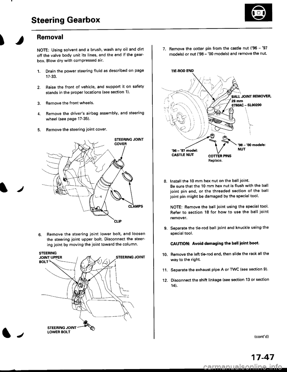
5. Bemove the steering joint cover.
6. Remove the steering joint lower bolt, and loosen
the steering joint upper bolt. Disconnect the steer-
ing joint by moving the ioint toward the column
tJ
17-47
TIE.ROD END
7. Remove the cotter pin from the castle nut {'96 -'97
models) or nut ('98 - '00 modslsl and remove the nut.
BALL JOINT REMOVER.28 mm07MAC - SLqI2|X)
'98 - '00 mod.b:NUT
8.
COTTER PINSRepl6ce.
lnstall the t0 mm hex nut on the ball joint.
Be sure that the 10 mm hex nut is flush with the ball
joint pin end, or the threaded section of the ball
joint pin might be damaged by the special tool.
NOTE: Remove the ball joint using the special tool.
Refer to section 18 for how to use ths ball joint
remover.
Seoarate the tie-rod ball joint and knuckle using the
specialtool.
CAUnON: Avoid damaging tho ball ioint boot.
Remove the left tie-rod end, then slide the rack all the
way to the right.
Separate the exhaust pipe A or TWC (see section 9).
Disconnect the shift linkage (see section 13 or section
14).
(cont'd)
9.
10.
11.
12.
Page 1106 of 2189
Steering Gearbox
Disassembly (cont'd)
8. Remove cylinder lines A and B from the gearbox.
CYLINDER LINE gCYLINOCR LINE A
Drain the fluid from the cylinder fittings by slowly
moving the steering rack back and forth,
Remove the two flange bolts, then remove the valve
body unit from the gearbox. (See page 17-52 forvalve body unit disassembly.)
VALVE BOOY UNITFLANGE BOLT
10.
'96 - '97 mod.ls:32 mm SHIMS98 - '00 modok:WAVE WASHER
17-50
13. Loosen and remove the cvlinder end.
11. Drill a 3 mm (0.12 in) diameter hole approximatety
2.5 - 3.0 mm (0.10 - 0.12 in) in depth in the stakedpoint on the cylinder.
cAunoN:
o Do nol allow metal shavings to onter the cylin.
der housing.
. After romoying iha cylinder end, remova any
bur6 at the staksd point.
Dcpthi 2,5 - 3.0 mm {0.10 - 0.12 in}
CYUNDER
12. Hold the steering
snown.
gearbox using a C-clamp as