Page 888 of 2189

Description
Hydraulic Control {cont'dl
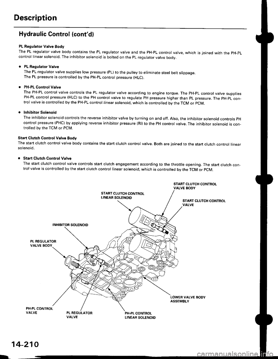
PL Regulator Valve Body
The PL regulator valve body contains the PL regulator valve and the PH-PL control valve. which is joined wirh the pH-pL
control linear solenoid. The inhibitor solenoid is bolted on the pL regulator valve body.
. PL Regulator Valve
The PL regulator valve supplies low p.essure (pL) to the pulley to eliminate steel belt slippage.The PL pressure is controlled by the pH-pL control pressure (HLC).
. PH-PL Control Valve
The PH-PL control valve controls the PL regulator valve according to engine torque. The PH-PL control valve suooliesPH-PL control pressure (HLC) to the PH control valve to regulate PH pressure higher than pL pressure. The pH-pL con-trol valve is controlled by the PH-PL control linear solenoid. which is controlled by the TcM or pcM,
. Inhibitor Solenoid
The inhibitor solenoid controls the reverse inhibitor valve by turning on and off. Also, the inhibitor solenoad controls pH
control pressure (PHC) by applying reverse inhibitor pressure (Rl) to the PH control valve. The inhibitor solenoid is con-trolled by the TCM or Pclvl.
Start Clutch Control Valv€ Body
The start clutch control valve body contains the start clutch control valve. Both are joined to the stan clutch control linearsolenoid.
. Start Clutch Control Valve
The start clutch control valve controls start clutch engagement according to the throttle opening. The start clutch con,trol valve is controlled by the stan clutch control linear solenoid, which is controlled bv the TCM o. pCM.
START CLUTCH CONTROLvAt-vE
LOWER VALVE BODYASSEMBI-Y
PH.PL CONTROLLINEAR SOLENOID
I.
14-210
Page 891 of 2189
E Position
Astheengineturns.theATFpumpa|sostartstooperate.F|uidfromtheATFpumpf|owstothePHregu|atorva|veandthe
c|Utchreducingva|ve.ThePHregu|atorva|veregu|ateshighpressure(PH).andsendittotheshiftVa|veandthePLregU'
latorvalve.Thehighpressure(PH)flowstothemovablefaceofthedrivenpulleyviatheshiftvalve'andturnsintolow
pressure(PL)atthePLregu|atorva|ve.Thelowpressure(PL}f|owstothemovab|e'aceofthedrivepu||eYviatheshift
valve. At this time, the pulley ratio remarns low'
Thehighpressure(px)uecomesttrectutchreducingpressure(CR)atthec|utchreducingva|Ve.Thec|utchreducingpres.
sure (CR) flows to the start clutch cont'oi uatt". tn"lt"n'al valve' the PH-PL control valve' and the shift control valve' and
is intercepted bY those valves
Under this condition, hydraulac pressure is not applied to the clutches and reverse brake'
(cont'd)
14-213
Page 901 of 2189
Component Locations
36 - 98 Models
BRAKE SWITCH
DRIVEN PULLEYSPEED SENSOR
INHIBITOR SOLENOID
ENGINE CONTROLMODULE IECMI
SECONDARY GEAR SHAFTSPEEO SENSOR
AUTOMATIC TRANSAXLE (A/T}GEAR POSITION SWITCI{
MANIFOLD ABSOLUTE
VEHICLE SPEEO SENSOR{vss}
IMAPI SENSOR
THROTTI.I POSITION {TPISENSOR
PH.PL CONTROLLINEAR SOLENOID
/i/ i,' / ,','4
,i/:1
t"--.---.- i,,
-_,-:-_a.--:
il
START CLUTCH CONTROLLINEAR SOLENOIDPULLEY
SHIFT CONTROLLINEAR SOLENOTD
$r,
14-224
h
SPEED SENSOR
Page 905 of 2189

TCM Terminal Voltage/Measuring Gonditions
('96 - 98 Modelsl
TCM Terminal Loc.tions
TCM-A l25P) Connecto.
TCM CONNECTOR A (26P}
TCM-B (22P) Connectot
2418910111213
1115161720232526
Terminal NumbetSignalDsscriptionMoasuring Conditions/Torminsl Vohrgo
A1SC LS_Stan clutch control linear solenoidpower supply negative electrodeEngine idling, E position:Approx. 0.4 VHLC LS-PH-PL control linear solenoid Dowersupply negative electrodeEngine idling, E position:Approx. 0.7 V
Shift control linear solenoid oowersupply negative electrodeEngine idling, E position:Approx. 0.8 V
A4LG1Ground
NEEngine speed signal inputWith engine running: Pulsing signalA6Not used
A7ATP LA/f gear position switch El positionsignal inputInEposition:OVIn other than El position: Approx. 1O VA8ATP Sly'T gear position switch E positionsignal inputIn lg position: 0 VIn other than E position: Approx. 10 VA9ATP DA{/T gear position switch E positionsignal inputIn lll position: 0 VIn other than E position: Approx. 10 VAr0ATP NPA,/T gear position switch E or Eposition signals inputInEorEposition:oVIn otherthan E orE position: Approx. 1O VA11ATP RA,/T gear position switch E positionsignal inputIn lE position: 0 VIn other than E position: Approx. 1O VA.12tGlPower supply systemWith ignition switch ON (ll): Banery voltsgeWith ignition switch OFF: 0 VA13PG1Ground
414Start clutch control linea. solenoidpower supply positive electrodeEngine idling, E position:Approx. 2.5 VA15HLC LS+PH-PL control line8|. solenoid powersupply positive electrodeEngine idling, El position:Approx. 5.0 VA16SH LS+Shift control linear solonoid oowersupply positive electrodeEngine idling, E position:Approx. 6.0 V417Ground
A18Not used
A19Not used
420D INDE indicator light controlWhen l9l indicator light comes on: Approx. jO VWhen lll indicator lighr OFF: 0 VA2'lNot used
422Not used
VBUBack-up power systemAlways battery voltage424Not used
A.25tG1Power supply systemWith ignition switch ON (lt): Baftery voltageWith ignition switch OFF:0 VPG1Ground
L
14-228
Page 906 of 2189

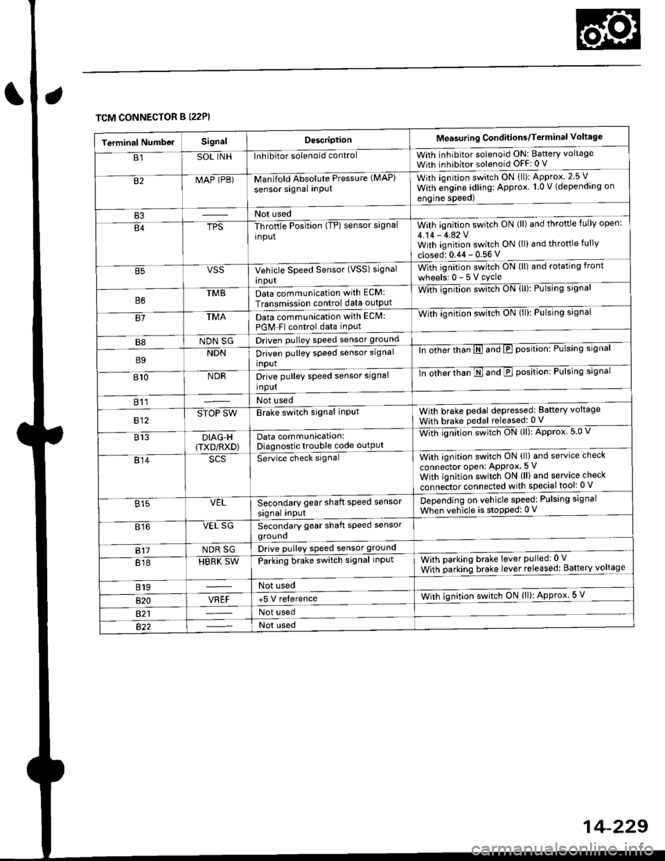
TCM CONNECTOR B (22P}
Terminal NumbelSignalDescriptionMeasuring Conditions/Terminal Voltage
B1SOL INHInhibitor solenoid controlWith inhibitor solenoid ON: Baftery voltage
With inhibitor solenoid OFF: 0 V
82MAP (PB)-M an if old Absol r-rte Pressure IMAP)
sensor signal inPUtWith iqnition switch ON (ll): Approx.2.5 V
With e;gine adling: Approx. 1.0 V (depending on
engine speed)
B3Not used
B4TPS-Throttle Position (TP) sensor signal
input
With ignition switch ON (ll) and throftle fully open:
4.14 - 4.42 VWith ignition switch ON (ll) and throttle fully
closed: 0.44 - 0.56 V
VSSVehicle Speed Sensor (VSS) signal
Inpur
With ignition switch ON (ll) and rotating front
wheelsr 0-5Vcycle
TMBData communication with ECM:
Transmission control data outpUt
With ignilion swltch UN lll): rulslng slgnar
81TMAData communication with EClvl:
PGM Fl control data inPut
With ignition swltch uN {ll,: l-ulslng slgnal
B8NDN SGDriven pulley speed sensor ground
B9NDNDriven pulley speed sensor signal
input
ln other thTnE and E position: Pulsing signal
810NDRDrive pulley speed sensor signal
Input
-tn ottrer ttran E ana E position: Pulsing signal
811Not used
812STOP SWBrake switch signal inPutWith brake pedal depressed: Battery voltage
With brake pedal released: 0 V
813DIAG-H(TXD/RXD)Data communication:Diagnostic trouble code outPut
Wittr ignitio.r s*itct' ON (ll): Approx 5.0 V
814Se-ice ctrect signatWith ignition switch ON (ll) and service check
connector oPen: APProx.5 V
With iqnition switch ON (ll) and service check
"onn"itot. connect"d with special tool: 0 V
Secondary gear shaft speed sensor
signal input
Depending on vehicle speed: Pulsing signal
When vehicle is stoPped: 0 V815VEL
816VEL SGSecondary gear shaft speed sensorgrouno
817NDR SGDrive pulley speed sensor ground
818HBRK SWParking brake switch signal inPutWith parking brake lever pulledr 0 V
With parking brake lever released: Battery voltage
819Not used
B�20VREF+5 V relerenceWith ignition switch ON (ll): Approx 5 V
821Not used
Not used
Page 925 of 2189
Electrical Troubleshooting ('96 - 9g Models)
Troubleshooting Flowchart - lgnition Coil
NOTE: Record all freeze data before you troubleshoot,
Po3rible Cause
. Dbconnected ignition coil con-nectol. Short o. op6n ignition coil wire' F.ulty ignition coil
Wire side ot female terminals
. OBD ll Scan Tool indicates CodePOl25.. Soll-diagnosis E indicarol lightindicates Code 11.
Measure NE Voltrge:1. Disconnect the A {26p) connector from the TCM.2. Start the engine.3. Measure the voltage betweenthe A5 and 413 or A26 termi-nals,
R6p.i. open or short in the wireb€lween the A5 te.minsl and thoignhion coil. It wir€ b OK, checkthe ignition coil test lsoc aoction23t.
ls there battery voltage?
Check for loose TCM connector.It nec$sery. substilute a known-good TCM and .echeck.
Page 936 of 2189
Troubleshooting Flowchart - Shift Control System
NOTE: Record all freeze data before you troubleshoot.
Po$ible Cause
Faulty 3hift control systemOgD ll Scan Tool indicates Code
P'1890.Self-diagnosi3 E indicator light
indicates Code 42.
Check for Anolhet Code:
Check whether the E indicator
light indicates another code.
Pertorm the TroubleshoolingFlowchrrt to. th€ indicet.d
Codelsl.
ls the E indicator light indi
cate another code?
Check Stall Speed RPM:Measure the stall speed RPM(see page 14-298).
ls the stall speed over 3,500 rpm?
ls the slall speed below 2.0o0 rpm)
Test-drive and Check E ngine
Speed:1. Drive the vehicle at 30 mPh(50 km/h) constantlY for sev_
eral manutes.2. Check the engine speed
ls the engine speed within the
specification (see page 14 296
and 14 297\?
14-259
Page 937 of 2189

Electrical Troubleshooting ('96 - 98 Models)
Troubleshooting Flowchart - Start Clutch Control System
NOTE: Record all freeze data before you troubleshoot.
Po$ible Ceuaa
Frulty start clutch cont.ol 3ys-tem
14-260
OBO ll Scan Tool indic.le3 Cod6P1891.Solt-diagnosis E indicator lightindicates Code (1.
Check for Another Codo:Check whether the @ indicatorlight indicates another code.
Poiform tho TroublcahootlngFlowchrrt lor the indicat.dCode(sl.
ls the E indicator light indi-cate another code?
Test Strrt Clutch Oper.tion:1. Turn the ignition switch OFF.2. Disconnect the 8P connectorfrom the solenoid harness con,nector.3. Start the engine, and shift toE position.4. Check whether the vehiclemoves.
Rcplaca th. strrt dudt r$amt ly.
Check Creeping Spe€d:1. Turn the ignition switch OFF.2. Reconnect the 8P connector tothe solenoid harness connec-tor,3. Start the engin6, and shift toE position.4. Check whether the vehiclecreeps, and chock the creep-Ing speed.
Does the vehicle move and isthe creeping speed approx.3mph (5 km/h)?
To page 14-261
E