Page 1969 of 2189

Brake System Indicator Light (cont'd)
- How the Circuit Works
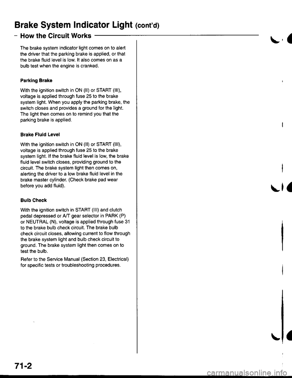
The brake system indicator light comes on to alert
the driver that the parking brake is applied, or that
the brake fluid level is low. lt also comes on as a
bulb test when the engine is cranked.
Parking Brake
With the ignition switch in ON (ll) or START (lll),
voltage is applied through fuse 25 to the brake
system light. When you apply the parking brake, the
switch closes and provides a ground for the light.
The light then comes on to remind you that the
parking brake is applied.
Brake Fluid Level
With the ignition switch in ON (ll) or START (lll),
voltage is applied through fuse 25 to the brake
system light. lf the brake fluid level is low, the brake
fluid level switch closes, providing ground to the
circuit. The brake system light then comes on,
alerting the d verto a low brake fluid level in the
brake master cylinder. (Check brake pad wear
before you add fluid).
Bulb Check
With the ignition switch in START (lll) and clutch
pedal depressed or A'lT gear selector in PARK (P)
or NEUTRAL (N), voltage is applied through fuse 31
to the brake bulb check circuit. The brake bulb
check circuit closes, allowing current to flow through
the brake system light and bulb check circuit to
ground. The brake system light then comes on to
test the bulb.
Refer to the Service Manual (Section 23, Electrical)
for specific tests or troubleshooting procedures.
71-2
a
\fa
Page 1973 of 2189

How the Gircuit Works
All Except GX
Do not smoke while working on the fuel system.
Keep open flame away trom the work area. Drain
fuel only into an approved container.
A thermistor is mounted in the fuel tank unit. When
the thermistor is cool, its resistance is very high.
When the thermistor's temperature increases, its
resistance decreases. Fuel in the fuel tank transters
heat away lrom the thermistor fast enough to keep it
cool so the thermistor's resistance stays high and
lhe low fuel indicator light does not come on. When
the fuel level drops below the thermistor, the
thermistor's temoerature increases. Without the fuel
to cool it, the thermistor's resislance decreases,
allowing current to llow through the low fuel
indicator light and the thermistor to ground, and the
low fuel indicator light comes on.
Refer to the Service Manual (Section 23, Electrical)
for specific tests or troubleshooting procedures.
GX
The PCM turns on the low fuel indicator light when
the fuel level is low. The PCM will also blink the
indicator light when a problem is detected by the
fuel tank pressure sensor or the fuel tank
temperature sensor.
Refer to the Service Manual GX Supplement
(Section 11 , Fuel and Emissions) for specific tests
or troubleshooting procedures.
74-1
Page 1976 of 2189

Indicators (cont'd)
I
I
I
I
't0 t
YEL
YEL
FUSE 2sUETER7.54
.I UNDER-DASH
IFUSE/RELAY
! F,gI".,I
IJ
See PowerDistribution,page 10€.
@f,*+* @sv#ftn* G)ffig^,", t
I
S€e Pow€r Distribution,page 10-6.
?-(: i#i',du), c401 ^t,a PHOfO 1J6I pHOfO 57 v"r vlEW 58
'99- 00 vehicles pre-wired foraccessory security system
I :7 r----r -7 ucHr \
i llEl lH lt*l
'.,
| | i r{rN/,6n1I I I l\y
//l I t
t--J-------Lfe---t---- ---JB8Y BsY B3YB8Y BsY -___B_3_Y_
,"' sfilJi:, i "*,*" i ;
""'"'*
! - "*-i
F"EIi,6HiJttr" so. sa venricres pre_w reo ror
I | : ".u,"r" ! ii|ot$,, accessory securrtv svstem
+ + l-----il------"rl';r'- ------------i
i "Lu,"r" ! rc;1rg (oPrroN) """"";:"J; !H;fi;"";Jt"'
l_____ll_ ____-v'_E\s!- __________-_i
o A csoeI PsOrO 6t
,----l-'':y:-
i """'^ I ".u"." -4 ELueLx 9 3B"rU"?'JYSJtttt :
See Low See Brake 6 Zl C503Fuel lndicator System ]l Paoro o'Light Inbicator ,____l_'':Y":-, BLU BLK ll _... _.._ q SECURTW SYSTEM, I BLU'BLK .. BLU/8!K : nourpcrrip
Coupe and Sedan
'96197 models
"ar,"a^ fi
'tg::1",,,
BLU/BLK
Jf v/Er,! e'98-'00 models
TRUNK LATCHSWITCHClosed withtrunk open.
"arr"a*l
qF*til'-""
* = Male-Femaleterminals reversedfor'99-'00 models
"'"'"i{ "^'
4r*liT;--'""""'-it:':
Bi?fi,,ri"li
".* | Page 14"12'
+ Fla'|",.
""'"'-lt
aLU/aLK see
i-< I'dli
-*TT
"'*f see cround
3rr< Sl"JliT:?s
".* I o*.,
0.1411'
* '&3i311'" ,:*'* ""dan €xcep, Gx)
80-2
Page 1981 of 2189
A/T Gear Position Indicator
{\
-cw
@UNDER-DASHFUSE/RELAYBOX
r
See A/TControls
"Ttr
See Dash andConsole Lights
-AYlltFED I FED/BLK I
tl
YEL
A1
SEE A,TTControls,PGM.FI
I
;l
A/T GcarPoiltlo{|Indlc{or
GAUGEASSEMBLY
a\
t----Y---
BLKBLU
12
GRNA!/HT
c410
vtEw 35
BLKaLu
I
See A,/TControls
TI
:I
a
ta
A.t 3
BLKBLU
7
BLK/BLU
eui [SBruI
SeelnterlockSystem
I
;+
ar
l
-;-----;++
-l-rl
c433
A/TGEARPOStTtONswrTcH
Sec GroundDistribution,pag€ 1+7.
Y
I
I
aL__l+: G401
\
89
Page 1982 of 2189
rT---'- UNDER.DASHI I FU3E25 I FUSE/RELAY
i i m* **J.e:1- iF,?T,'.aI l-----+ pags 1G6. IL.*--------J
a
- Allexcept CW
@E
-1
I-i
See A"|TControls
."r'*"*",iFI
llIftr;1'
.-a---{ csoT
'..[--[Eq"Ti**,,
o' I
- Pag€ 105'
:I GAUGEI ASSEMBLY
i'l;l:,tr?,'
I
I
I
I
I
I
I
I
I_J-(y'g,--
f#**
"."i?
t----g--
aA11
I
:+
arLa
A13
BLVBLU
BlVBIU
Bu( lFBLU ISeelnterlockSystem
BLX/BLU
Ga rryvST
A/TGEARPOSTTTONSWITCH
: S€e GfoundI Disribution,- paga r.l- /.
L__i
= G401
S€e Cruise Conbol
See GmundDistrihJtion,page 1+5.c433
vtEw11
ALK
1
BLK
See Dash andConsole Lights
+r
BEO I AED/BLX I
ITAJA AZ t
S€e A,/TControls
;:I
ru
Page 1983 of 2189

A/T Gear Position Indicator (conrd)
- How the Circuit Works
With the ignition switch in ON (ll) or START (lll),
voltage is applied to the A,/T gear position indicator.
The A,/T gear position switch provides a ground for
each position. As an input is grounded, its indicator
light comes on. lf you select R, for example, ground
will be provided to the input of the A,/T gear position
indicato( and the R indicator will come on.
With the headlight switch in PARK or HEAD, voltage
is applied to the RED/BLK wire terminal. This
changes the indicator panel illumination from fixed
to controlled by the dash lights dimmer input
through the RED wire.
When the powertrain (all except '96-'98 CVT) or
transmission ('96198 CVT) control module (PCM or
TCM) detects an abnormality in the automatic
transmission control system, or when you request
diagnostic trouble codes through the service check
connector, the PCM or TCM will make the D4 (D for
CVT) indicator light blink.
Refer to the Service Manual (Section 14,
Automatic Transmission) for specific tests or
troubleshooting procedures.
\ia
89-2
Page 2002 of 2189
Fog Lights
_ Vehicles pre'wiredfor accessorysecurity system
SECURITY SYSTEMCONNECTOR(oPT|ON)
"!'19*13*
u,.*,"
a
c403
----.t COMB|NAT|ON
: swrrcHI PHOIOT2
lvtEw u
I
I
FOG LIGHTIN-LINE FUSE
FUSFI H,'lt.cw 8llaa
BLKI .--<
t_G2O2
gee GroundDistribution,pag€ 144.
i t-' BsJ:?'tr! li[?i,i'*'LJ------J
_ _tlI',-Yfi::"* *,*,,
a,
ot'
tttr(
---g-----J _- -"il( - see H€dbnt
;eo'q;r. I-) oaoe loo.
See Headlights '(Canada)
l-l 1 aeomnr
k-j'/,-dl15 llJ - - oplronal Fog Light swttch Harness - - -.I UNOER.DASH
I FUSE/RELAY
FUSE2l I BOx
R H/r- i PHoro 5errow BEA
I
---!':--J--1frf':l,"
i::.,.n.*BEo,naHT I !7
*':#i,!J
^ L--8-
i33o,,nno t f-
"-'-:E+
1 10-10
Page 2004 of 2189
Headlights
- Coupe and Sedan
Vehicles pre-wired- - - for accessorysecurity system
5 f| C419 PHQ|O63 vtEW4s
UNDER-HOOD| / FUSE 48 | FUSE/RELAY: HEADLTGHT :BOXI I 3oa I pHoroT
LJ----JI Y C3s2wHrl PYo-rg8- ulEY:?- - - - - - canadaWHT
Head-ligtrtSwlich
COMBINATIONLIGHTswrTcH
".;L
L--{..---1 Y Cs01
".o,o"n I i[?,lo,uo ^..?fiurti
ce.l, *i;[fl?ive /a V|EW z1
i--r------''i
/A xrcx geru
;".1p$31"f'""InoFY;�]j:::-:
T_l Eqr I--g------J
RIGHTHEADLIGHT
lL
r-: G401PHOTO 57
See GroundDistdbution,page 14-4.
Soe GroundDistribution,page 14-4.
SECURIry SYSTEMCONNECTOR(oPTloN)i t-'d*ltr! lF"{il'.]'*'
nero't t-+- *.oo*jpinx I pl66 HEAo J cmx
- Canada -
---J4- ----J See HeadliohtB1 Y Swirch,-.^^-- I# oao6 100.
FUSE 21F i/tIOW AEAM
FUSE 4B H/LHIGll BEAM
UNDER.DASHFUSE/RELAYBOX
1IIGH
110-12