Page 1827 of 2189

How To Use This Manual
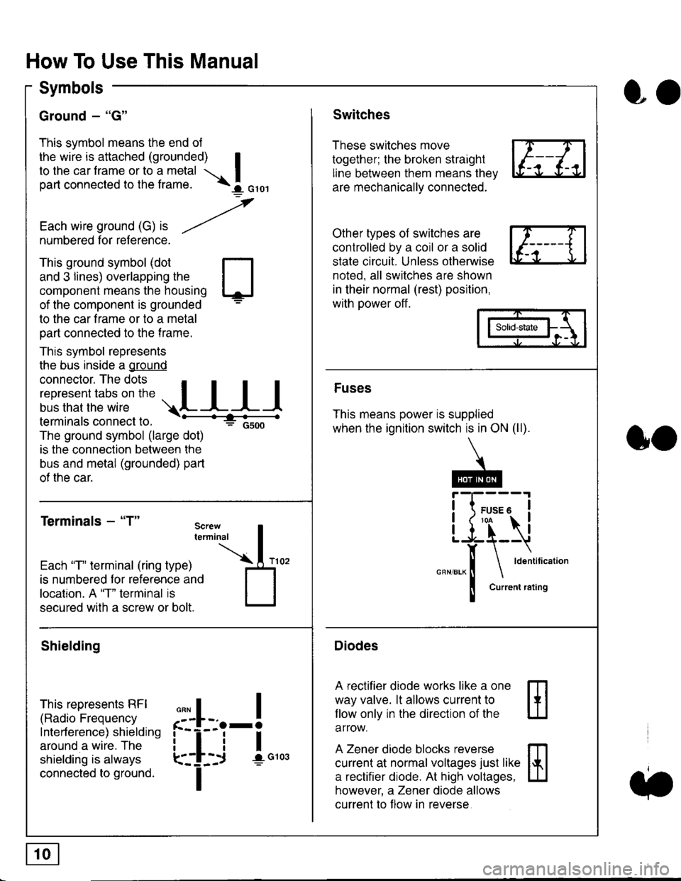
Symbols
Ground - "G"
This symbol means the end ol
the wire is attached (grounded) Ito the car frame or to a metal I
part connected to the frame. \i oro,|
-t'
Each wire ground (G) it --/
numbered for reference.
oo
Switches
These switches move
together; the broken straight
line between them means the,
are mechanically connected.
Other types of switches are
controlled by a coil or a solid
state circuit. Unless otherwise
noted. all switches are shown
in their normal (rest) position,
with power off.
This ground symbol (dot
and 3 lines) overlapping the
component means the housing
of the component is grounded
to the car frame or to a metal
part connected to the frame.
This symbol represents
the bus inside a ground
connector. The dots I
i:l*,':1,'^:*,:"
;"
r"L I I I
terminals connect to.
The ground symbol (large dot)
is the connection between the
bus and metal (grounded) part
of the car.
Terminals - "T"
ffi
ffi
Solid-state
Fuses
This means power is supplied
when the ignition switch is in ON (ll).
Current rating
Diodes
A rectifier diode works like a one
way valve. lt allows current to
llow only in the direction of the
arrow.
A Zener diode blocks reverse
current at normal voltages just like
a rectifier diode. At high voltages.
however, a Zener diode allows
current to f low in reverse
oo
Each "T" lerminal (ring type)
is numbered for reference and
location. A "T" terminal is
secured with a screw or bolt.
Shielding
This represents RFI
(Radio Frequency
Interference) shielding
around a wire. The
shielding is always
connected to ground.
f--l;j-i",..
I
,,,,
T
Page 1829 of 2189

In the "OHMS" range, the DVOM will measure
resistance between two points along a circuit.
Low resistance means good continuity.
Diodes and solid-state devices in a circuit can
make a DVOM give a false reading. To check
a reading, reverse the leads, and take a
second reading. lf the readings differ, the
component is affecting lhe measurement.
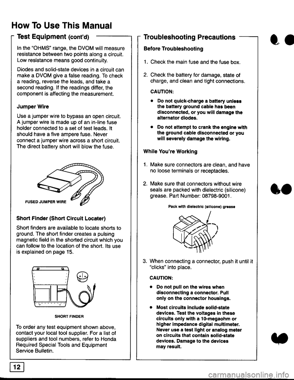
Jumper Wire
Use a jumper wire to bypass an open circuit.
A iumper wire is made up ot an in-line fuse
holder connected to a set of test leads. lt
should have a five amoere fuse. Never
connect a jumper wire across a short circuit.
The direct battery short will blow the fuse.
Short Finder (Short Circuit Locater)
Short finders are available to locale shorts to
ground. The short tinder creates a pulsing
magnetic field in the shorted circuit whlch you
can follow to the location of the short. lts use
is explained on page 15.
SHORT FINDER
To ordei any test equipment shown above,
contact your local tool supplier. For a list of
suppliers and tool numbers, refer to Honda
Required Special Tools and Equipment
Service Bulletin.
How To Use This Manual
Test Equipment (cont'd)
oa
Troubleshooting Precautions
Before Troubleshooting
1. Check the main fuse and the fuse box.
2. Check the battery for damage, state of
charge, and clean and tight connections.
CAUTION:
. Do not quick-charge a battery unlers
the battery ground cable has been
disconnected, or you will damage the
alternator diodes.
. Do not attempt to crank the engine wlth
the ground cable disconnected or you
will severely damage the wiring.
While You're Working
1. Make sure connectors are clean, and have
no loose terminals or receptacles.
2. Make sure lhat connectors without wire
seals are packed with dielectric (silicone)
grease. Part Number: 08798-9001 .
Pack wllh dlelectrlc (sillcons) greass
When connecting a connector, push it until it"clicks" into place.
Do not pull on the wires when
disconnecting a connector. Pull
only on the connector houslngs.
Most circuits Include solid-state
devlces. Test the voltages In these
circuits only with a lo-megaohm or
higher impedance digital multlm6ter.
Never use a test light or analog meter
on chcuits that contain solld-state
devices. Damage to the devices
may result.
oo
Page 1923 of 2189

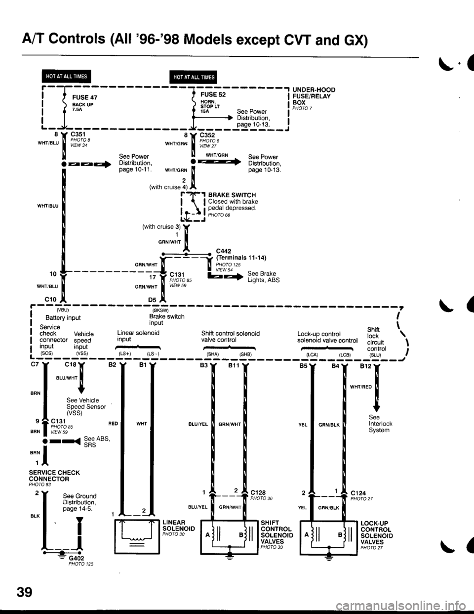
A/T Controls (All '96-'98 Models except CW and GX)
r.(
r5A see power I
--li$"i':,--iL-.At----- __*____..,,53-j"i__8 Y 93^s_1- 8Y C352'"'".u
I iii'i"' ""'o"* | i#?1o.'
ll see power ll wrr cnn See Power
la--- oisirioution, ! -t 6iri,iortion,
[--*
t"*tr*t1,'.':,:;i. wHr GFN lt page 10-13.
,i(with crurse 4) Al"'rl(-1 BRAKE swrrcH
| lClosed.with brake
Ir-I Il,?,|fll,"P'"""oL*--J
c18lr 82
"ar-"t I
I
See VehicleSpeed Sensor(vss)
ct31PHO|O 35vtEw 59
r< See ABs'
UNDER"HOODFUSE/RELAYBOXI
I
I
BFN
9
BFN
o
""il
SERVICE CHECKCONNECTOR
See GroundDistribution,page 14-5.
I
YEL
c124
L__lH:""".: G402
SHIFTCONTROLSOLENOIDVALVES
LOCK-UPCONTROLSOLENOIDVALVES
,. L ---- - - --.#ku" :::::'o f
---------tty"c;11,, l;-,f l;?t?:if,-:;tr *";.!, *"
c10 ,| Ds^'
I Lvou, (SKSV,
! Battery input Brake lwitch I
service nPUt ehin t;;;;i- Vehrcte Linear sotenoid Shift controt sol€noid Lock-up conkol iJ'[
'\
connector speed input valve conhol solenoid vatve controt tliiJ"it \uo trut tconrrol t: (scs) (vss) {Ls}) rLs ) {sHA' {SHB, (LCA) (LCB) {S-U) .--:-'--J
ct28
39
GFN/ALK
(
Page 1928 of 2189
aI
I coNrRoL
EcM EcM lllg?.Y.ERelernce control data control I H;,."voftase output ff.'nour a;i:;Y"*- lug'L - - - - JS- - - - - J't3'- - - iA25Y CgY C30Y
lL
I 1=,
-"'"'"1 ""1 "-l
rRANsM,ss,oN
,r, ,[ ", I ". I
"oou".-o'"[3fl!
NnEF) O[,!A) OMB)Beference ECM control ECM control D..r.i.^vollage data input data output ;;ii; vI
t
swrtch
CVT transmrssion conlrol solenoids signal DTC CVT grounds
j input outputlPcrr /pcl).t HLC LS I iHLC LS+l {SC LS-) tSC LS-) (SH Ls-i ISH LS-l ISOL INH' THBRK SWt {O'AG Hr {LGli {LGl) lPclr tpclj :
{*n*
:".,1 :"::.1 i.lnu+
',sk,-[lr*:[l*':t'
*?:?' """",.0-fr;rt.o,1^,, *'ig"#"t I""-t cw i
-"' iiio lr.'t l
lsel$tfis'! I !
izf-"{}Y
f,====i iiu:'" !
I ii,l;?:' i
lt r---L
4 9::1",- (cont'd)
39-s
PH.PL START SHIFTCONTFOL CLUTCH COITTROLLINEAR CONTROL LINEARSOLENOID LINEAR SOLENOIDSOL:NOID
Page 1931 of 2189
A/T Controls (All GX and All '99-'00 Models except CVI)
a
i-l-;;;
-rffi;----t
H*B'""i
! l r*-* i iflsln- :eepower ii|iii '
L_l____ _-i"utuiF#'i8 Y 93-s_1 SY C3s2 :""'".u I i,i?lol *"'o"n I iffl,1of
ll see eower ll wxrcnl - see power :
@
c131
vlEw 59
See GroundDistribulion,page 14-5. 1
["*
t*,t*;,,
;ffi i-
iilnirir,
Distribution,page 10-5.
,D5
, ry8 SOr)I Power source
BLI(YEL
il
10
WHT/BLU
821
(VBU)
Banery input
Servicecheck Vehicls Linear sol€noidconneclor speednput
' for solenoid valve ; \
Lock-up controlsolenoid valve (valve control circuitShift lock \
c'124
a
inpulinput
{8KSW)Brake switchInput
Shilt control solenoidvalve control
:::l
",:::[""::
. | .ir:Til**'
''lizll:l,,' i*'";l'-.----.'
O rr<( !!e"A65,
""il
SERVICE CHECKCONNECTOR
c12A
LTGRN/
I
SH IFTCONTROLSOLENOIDVALVES
LOCK.UPCONTROLSOLENOIDVALVESL__l+: G402a
il*-
except GX
See Powerr?F.| BRAKE SWTTCH
| | Closed with brake
| 1-I | !;€ja oeo'"""o
39-8
Page 1936 of 2189
?uTi'i'------lUNDER.OASHFUSE/RELAYBOX
UNDER-HOODFUSE/RELAYBOXfI,€! PtfiP
f#rntt)See PowerDistribution,
iT;;*-l
rr:_i
y;lftr,.:{'
page 10-2.tJ---------J" Y 3,,t"?:"""""T
[']':.
i-?;;ffi;
i_f___
PGM-FIMAINRELAY
;;II
;;;I
c't0'l
vtEw 28
TI
":{
c130Oerminals l4-17)
vlEw 52
I . (rGP1) i 1rGP2) - I
Power input
..���������������
SeePGM,FI
POWER.TRAINCONTROLMODULE(PcM)PHO|O 86
(cont'd)
\!
CW hansm|ssion_ control solonoids Ground I
t (HLC LS-) THLCLS+) (SCLS-) (SCLS'I iSH LS I rSHLS+j ISOLINHI lPGr) (PO2) (LG1) rLG2r IL-------i:---- ---------J
-T1
Tj
:1 ;
lruffil
GRNBLII
cl16(Terminals8-14)
vlEW 39BLK
CVTTRANS.MISSIONSOLENOID
See GroundDistribution,page 14-2.
BRN/BLK
PH.PL START SHtF'CONTROL CLUTCH CONTNOLUN€AR CONTNOL LINEARSOLENOID UI{EAR SOLENOIDsoLEltotD
:_-:_-___1
-t
1-! |
Ti11:a__J
BRN/BLK
39-13
Page 1957 of 2189

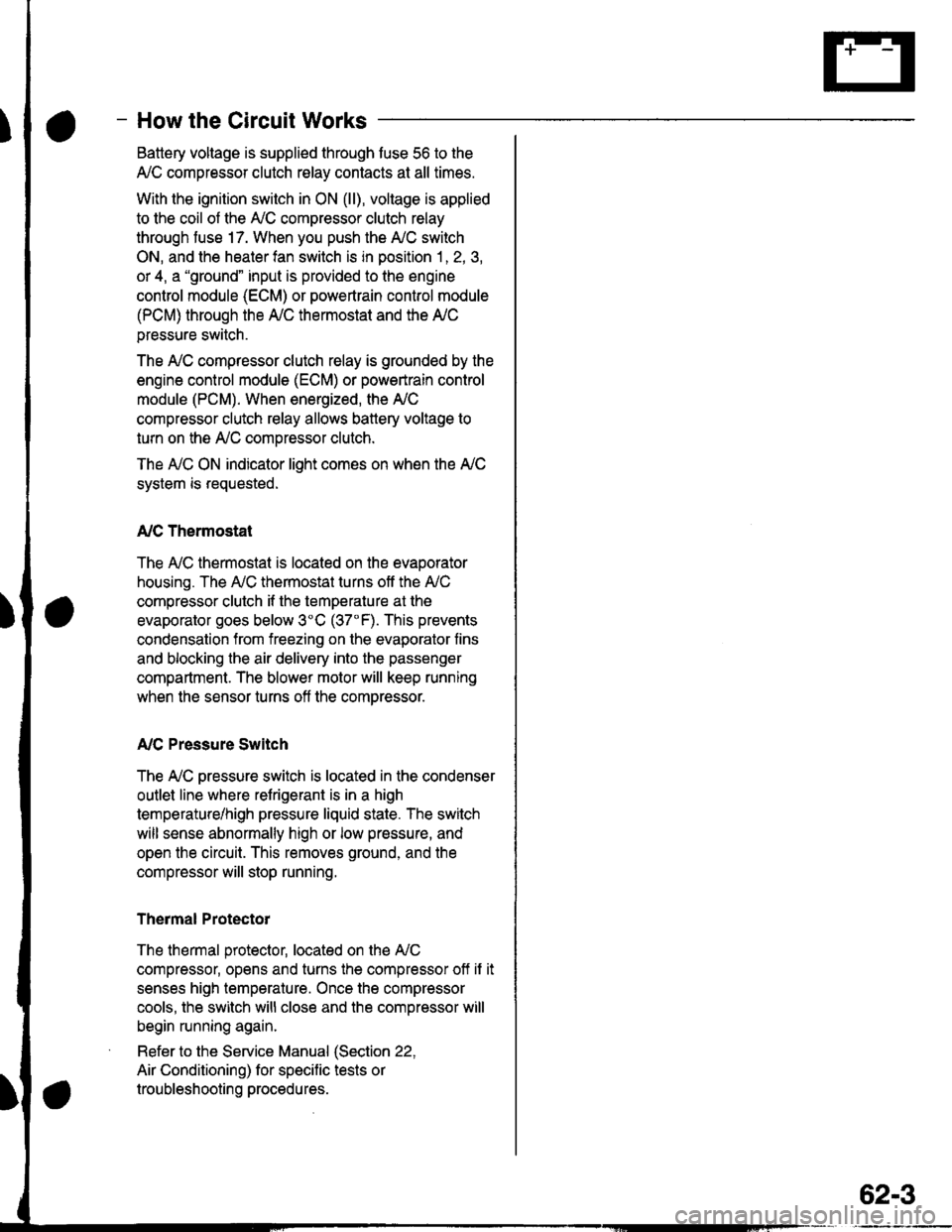
- How the Circuit Works
Battery voltage is supplied through tuse 56 to the
A,/C compressor clutch r€lay contacts at all times.
With the ignition switch in ON (ll), vollage is applied
to the coil of the A,/C compressor clutch relay
through fuse 17. When you push the A,/C switch
ON, and the heater fan switch is in position | , 2, 3,
or 4, a "ground" input is provided to the engine
control module (ECM) or powertrain control module
(PCM) through the l'lC thermostat and the l'lC
pressure switch.
The A,/C compressor clutch relay is grounded by the
engine control module (ECM) or powertrain control
module (PCM). When energized, the A'lC
compressor clutch relay allows battery voltage to
turn on the A,/C comDressor clutch.
The A,/C ON indicator light comes on when the A,/C
system is requested.
A,/C Thermostat
The A'lC thermostat is located on the evaoorator
housing. The A,/C thermostat turns off the A,/C
compressor clutch if the temperature at the
evaporator goes below 3'C (37'F). This prevents
condensation from freezing on the evaporator fins
and blocking the air delivery into the passenger
compartment. The blower motor will keep running
when the sensor turns off the comDressor.
A,/C Pressure Switch
The fuC oressure switch is located in the condenser
outlet line where refrigerant is in a high
temperature/high pressure liquid state. The switch
will sense abnormally high or low pressure, and
open the circuit. This removes ground, and the
compressor will stop running.
Thermal Protectot
The thermal protector, located on the A,/C
compressor, opens and turns the compressor off if it
senses high temperature. Once the compressor
cools, the switch will close and the compressor will
begin running again.
Refer to the Service Manual (Section 22,
Air Conditioning) for specific tests or
troubleshooting procedures.
62-3
Page 2002 of 2189
Fog Lights
_ Vehicles pre'wiredfor accessorysecurity system
SECURITY SYSTEMCONNECTOR(oPT|ON)
"!'19*13*
u,.*,"
a
c403
----.t COMB|NAT|ON
: swrrcHI PHOIOT2
lvtEw u
I
I
FOG LIGHTIN-LINE FUSE
FUSFI H,'lt.cw 8llaa
BLKI .--<
t_G2O2
gee GroundDistribution,pag€ 144.
i t-' BsJ:?'tr! li[?i,i'*'LJ------J
_ _tlI',-Yfi::"* *,*,,
a,
ot'
tttr(
---g-----J _- -"il( - see H€dbnt
;eo'q;r. I-) oaoe loo.
See Headlights '(Canada)
l-l 1 aeomnr
k-j'/,-dl15 llJ - - oplronal Fog Light swttch Harness - - -.I UNOER.DASH
I FUSE/RELAY
FUSE2l I BOx
R H/r- i PHoro 5errow BEA
I
---!':--J--1frf':l,"
i::.,.n.*BEo,naHT I !7
*':#i,!J
^ L--8-
i33o,,nno t f-
"-'-:E+
1 10-10