Page 1560 of 2189

lgnition Switch
Steering Lock Replacement
SRS components are located in this area. Review theSRS component locations. precautions, and procedures
in the SRS section (24) before performing repairs or ser-vtce.
Remove:
LMake sure you have the anti-theft code for theradio, then wire down the frequencies for theradio's preset buttons ('99 - 00 models).
Disconnect the battery negative cable.
Remove the driver's dashboard lower cover andknee bolster (see section 20).
Disconnect the 5P connector from the under-dash
fuse/relay box and the 7P connector from the mainwire harness (see previous page).
Remove the steering column covers, then removethe mounting bolts and nuts from the steering col-umn (see section l7).
Lower the steering column assembly,
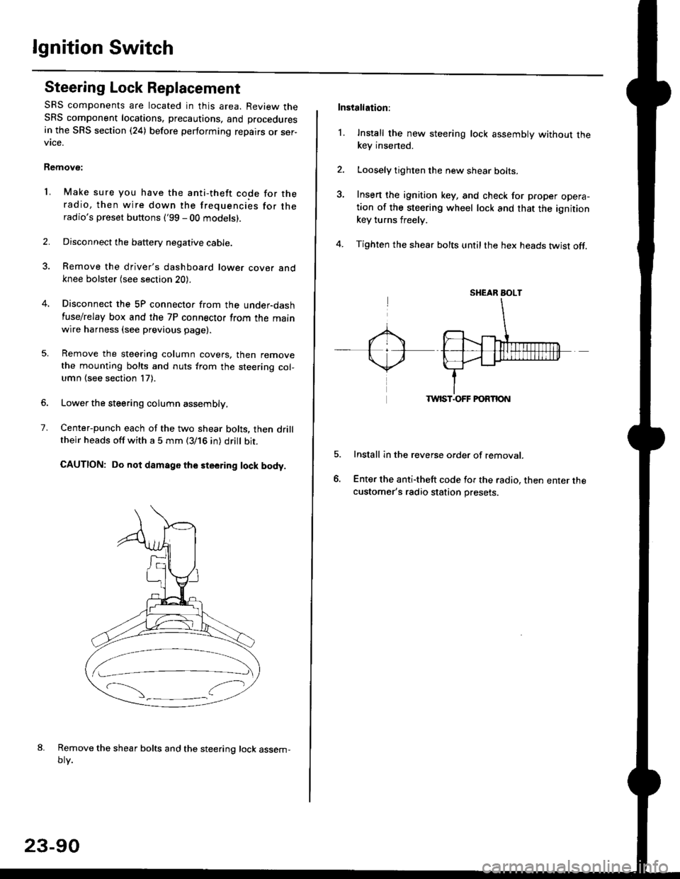
Center-punch each of the two shear bolts, then drilltheir heads off with a 5 mm (3/16 in) dritt bit.
CAUTION: Do not damago the steering lock body.
Remove the shear bolts and the steering lock assem,oty.
2.
1.
23-90
Installation:
l. Install the new steering lock assembly without thekey insened.
Loosely tighten the new shear bolts-
Insert the ignition key, and check for proper opera-tion of the steering wheel lock and that the ignitionkey turns freely.
Tighten the shear bolts untilthe hex heads twist off.
TWIST.OFF FORTION
Install in the reverse order of removar.
Enter the anti-theft code for the radio, then enter thecustomer's radio station presets.
sr{€aR SroLT
Page 1805 of 2189

Airbag
)Replacement
After a collision in which the airbags were deployed' the
airbag assemblies and the SRS unit must be replaced'
!!!@ Store a removed airbag with the pad sur'
iFup. rr trt" airbag is improperly stored face down'
accidental deployment could propel the unit with
enough force to cause serious iniury'
CAUTION:
. Always disconnsct lhe airbag conn€ctor(s) when the
harness is disconnected.
. Do not disassemble or tamper with the ailbag'
NOTE:
. Do not install used SRS parts from another vehicle'
When repairing, use only new SRS parts'
o Carefully inspect the airbag before you install it Do
not insiall an airbag that shows signs oI being
dropped or improperly handled, such as dents' cracks
or deformation.
1. Disconnect the battery negative cable' then discon-
nect the positive cable from the battery' and wait at
least three minutes
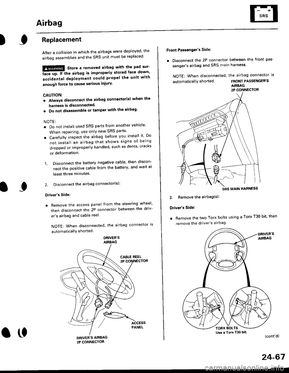
2. Disconnect the airbag connector(s):
Driver's Side:
. Remove the access panel from the steering wheel'
then disconnecl the 2P connector betlveen the driv-
er's airbag and cable reel
NOTE: When disconnected, the airbag connector ls
automaticallY shorted
ORIVER'SAIRBAG
DRIVEE'S AIRBAG2P CONNECTOR
oo
Front Passengel's Side:
. Disconnect the 2P connector between the front pas-
senger's airbag and SRS main harness'
NOTE: When disconnected, the airbag connector is
automaticallY shorted.FRONT PASSENGER'S
AIRBAG2P CONNECTOR
3. Bemove the airbag(s):
Driver's Side:
. Remove the two Torx bolts using a Torx T30 bit' then
remove the driver's airbag
(cont'd)
24-67
SRS MAIN HARNESS
Use a Torx T30 bitTORX BOLTS
Page 1806 of 2189
Airbag
Replacement (cont'd)
Front Passenger's Side:
. Remove the three mounting nuts from the bracket,then remove the harngss clip.. Lift the front passenger's airbag out of the dashboardby covering the lid and dashboard with a cloth, andprying carefully with a flat-tip screwdflver.
NOTE: The lid of the airbag has pawls on its sidewhich attach it to the dashboard.
24-6a
CAUTION: B€ sure to inslall the SRS wiring so that it isnot pinched or interforirg with other parts.
4. Installthe new airbag(s):
Driver's Side: Place the driver,s airbag into the steeringwheel, and secure it with new Torx botrs.
TORX BOLTS9.E N.m (1,0 kgf.m, 7.2 tbt ftlReplace.
Front Pass€ngar's Side:
. Place the front passenger,s airbag into the dash-board.
. Tighten the front passenger,s airbag mounting nuts.
ANAAG MOUNTING NUTS9.8 N.m 11.0 kgf.m, 7.2lbf.frlReplace.
DRIVER'S AIRBAG
Page 1810 of 2189

Gable Reel
Replacement
!@@ store a .emove airbag assambly with thepad surtace up. lf the airbag is improperly stored face
down, accidental deploymont could propel the unit withenough force to cause sorious iniury.
CAUTION:
. Alwsys disconnect the airbag connoctor(s) when ih€harness is disconngcted.
. Do not disassemble or tamper with the airbag.
NOTE: Carefully inspect the airbag assembly beforeinstalling it. Do not install an airbag that shows signs ofbeing dropped or improperly handled. such as dents,cracks or deformation.
l.Disconnect the battery negative cable. then discon-nect the positive cable from the battery, and wait atleast three minutes.
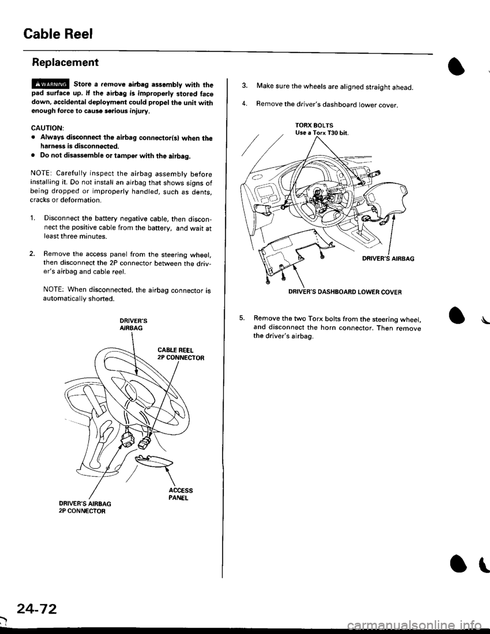
Remove the access panel from the steering wheel,then disconnect the 2P connector between the driv-er's airbag and cable reel.
NOTE: When disconnected, the airbag connector isautomatically shorted.
DRIVER'SAIRBAG
)
24-72
or
TORX EOLTSUse a Torx T30 bit.
DRIVEB'S DASHBOARD LOWER COVER
4.
Make sure the wheels are aligned straight ahead.
Remove the driver's dashboard lower cover.
5. Remove the two Torx bolts from the steering wheel,and disconnect the horn connector. Then removethe driver's airbag.
\
Page 1814 of 2189

SRS Unit
Replacement
CAUTION:
. Betore disconnoqting lny pErt of the SRS wire hal-ness, disconnect th9 airbag conn"ctorlsl.. During installltion or teplacemsnt. do not bump(impact w.cnch, hamm€r stc.l the area noar tho SRSunit.
NOTE:
o Do not damage the SRS unit terminals or connectors.. Do not disassemble the SRS unit; it has no service-able parts,
. Store the SRS unit in a clean, dry a.ea,. Do not use any SRS unit which has be€n subjected towater or shows signs of being dropped or improperlyhandled. such 8s dents, cracks or deformation.
1. Disconnect the bsttery negative cable. then discon-nect the positive cable from the battery, and wait atleast three minutes.
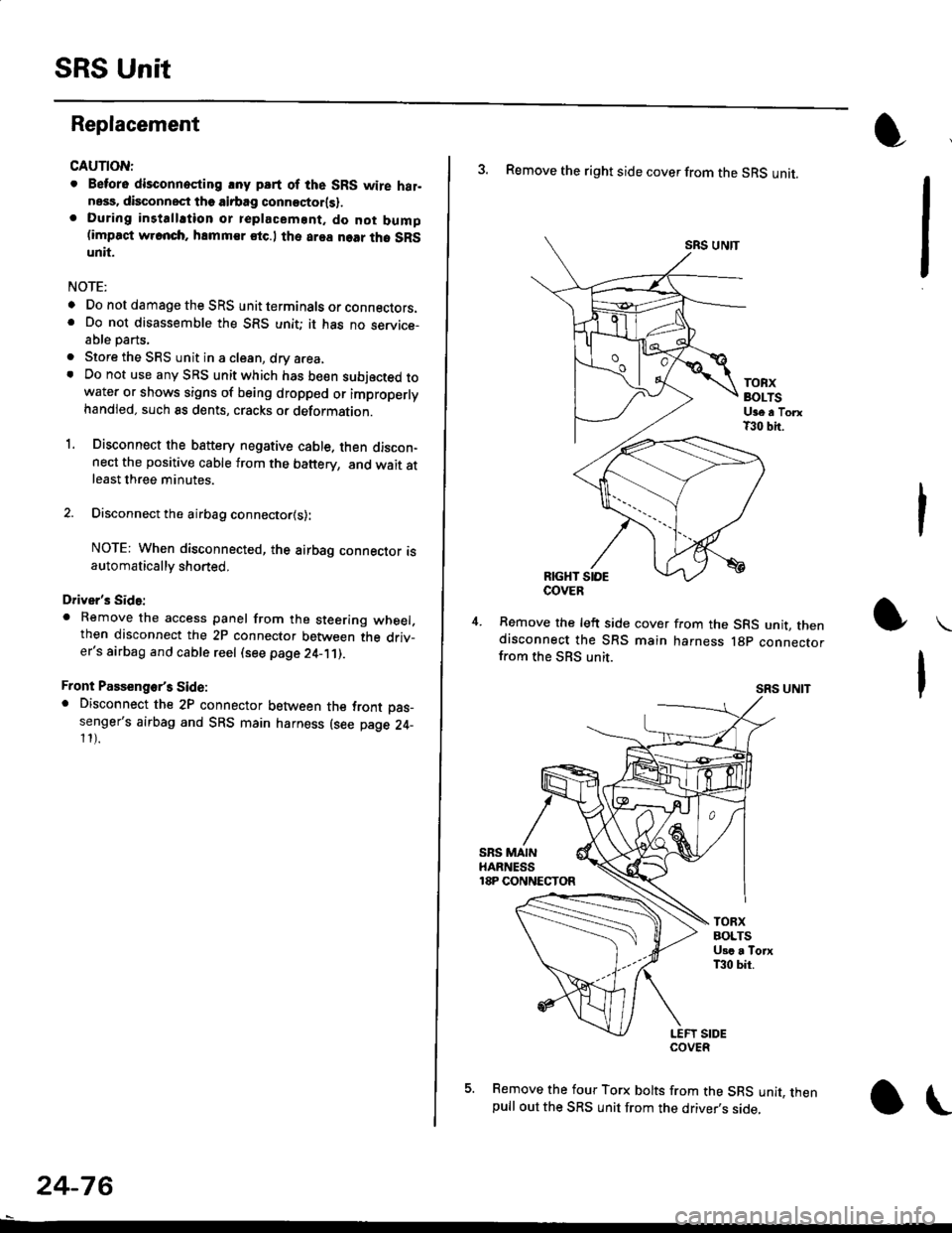
2. Disconnect the airbag connector{s}:
NOTE: When disconnected, the airbag connector isautomatically shorted,
Driver's Side:
. Remove the access panel from the steering wheel.then disconnect the 2P connector between the driv_er's airbag and cable reel (see page 24-11).
Front Passenge/s Side:. Disconnect the 2P connector between the tront oas_senger's airbag and SRS main harness (see page 24-11).
24-76
o\
3. Remove the right side cover from the SRS unit.
SRS UNTT
TOBXBOLTSUge a TorxT30 bit.
RIGHT SIOE
Remove the left side cover from the SRS unit, thendisconnect the SRS main harness lgp connectorfrom the SBS unit.
SRS UNIT
5. Remove the four Torx bolts from the SRS unit, thenpull out the SRS unit from the driver,s side,
COVER
Page 1815 of 2189
6. Install the new SRS unit.
NOTE: Do not reuse a torx bolt that has red
threads. Replace the bolt with a new one.
)
7.
TORX BOLTS9.8 N.m l'1.0 kg{.m, 7.2 lbf.ft}Use a Torx T30 bit.
Connect the SRS main harness l8P connector to the
SRS uniu push it into posjtion until it clicks.
Install the SRS unit covers (ri9ht and left). Make
sure the covers snap together in the middle.
8.
TORX BOLTS9.8 N.m 11.0 kgf.m, 7.2 lbf.ft)U3e . Torx T30 bit.
SRS MAIN HARNESS
)(l
9.
10.
't2.
Reconnect the driver's aibag 2P connector to the
cable reel 2P connector, then reinstall the access
panel on the steering wheel.
Reconnect the tront passenger's airbag connector
to the SRS main harness.
Reconnect the battery positive cable, then the nega
tive cable.
After installing the SRS unit, confirm proper system
operation: Turn the ignition switch ON (ll); the SRS
indicator light should come on for about six seconds
and then go oif.
11.
24-77
.-