1999 HONDA CIVIC Injector
[x] Cancel search: InjectorPage 1496 of 2189
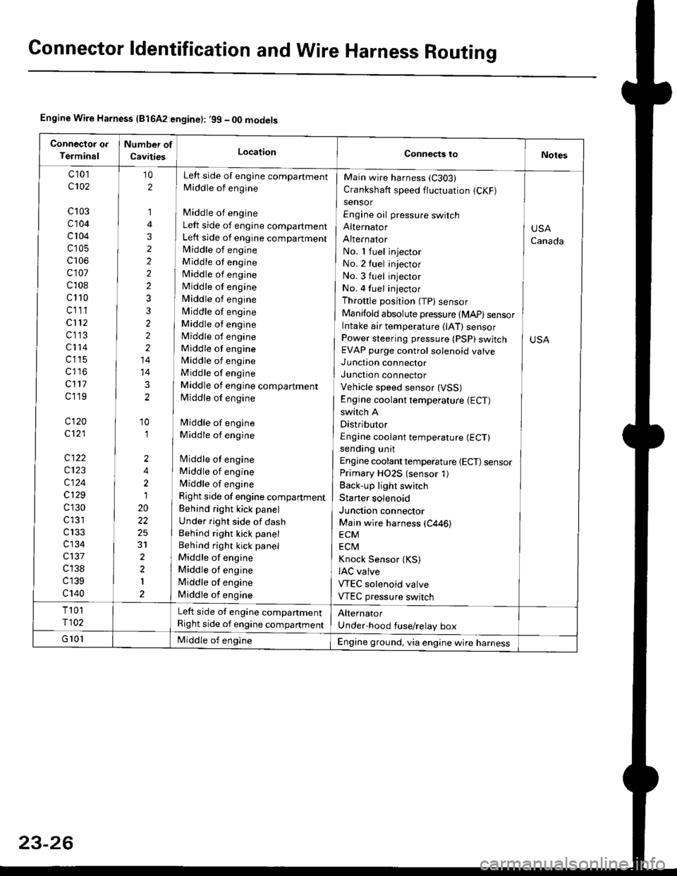
Connector ldentification and WireHarness Routing
Engine Wire Harness {81642 engine}: .99 - 00 models
c 101
c102
cl03
c104
c 104
c'105
c106
cl01
c108
c110
cl11
cl12
c1'13
c114
c115
c117
cl19
c120
c121
c122
c123
c124
c129
c130
c l31
c133
c134
c137
c 138
c139
c140
Left side of engine companment
Middle of engine
Middle of engine
Left side of engine compartment
Left side of engine compartmentlvliddle of engine
Middle ot engine
Middle of engine
Middle of engine
Middle of engine
Middle of engine
Middle ot engine
Middle of engine
Middle of engine
Middle of engine
Middle of engine
Middle of engine compartment
Middle of engine
Middle of engine
Middle of engine
lMiddle of engine
Middle of engine
Middle of engine
Right side of engine compartment
Behind right kick panel
Under right side of dash
Behind right kick panel
Behind right kick panel
Middle of engine
Middle ot engine
lMiddle of engine
Middle of engine
10
2
,]
4
3
2
2
2
2
3
3
2
2
2
14
14
3
2
'10
'I
2
4
2
1
20
22
25
31
2
2
I
Main wire harness (C303)
Crankshaft speed fluctuation (CKF)
sensor
Engine oil pressure switch
Alternator
Alternator
No. 1 fuel injector
No. 2 tuel injector
No. 3 fuel injector
No. 4 fuel injector
Throttle position (TP) sensor
Manifold absolute pressure (MAP) sensorIntake air temperature (lAT) sensorPower steering pressure (PSP) swjtchEVAP purge control solenoid valve
Junction connector
Junction connector
Vehicle speed sensor (VSS)
Engine coolant temperature (ECT)
switch A
Distributor
Engine coolant temperature (ECT)
sending unit
Engine coolant temperature {ECT) sensorPrimary HO2S (sensor 1)
Back-up light switch
Starter solenoid
Junction connector
Main wire harness (C446)
ECM
ECtvl
Knock Sensor {KS)IAC valve
VTEC solenoid valve
VTEC pressure switch
USA
Canada
Left side of engine companment
Right side of engine compartment
Engine ground, via engine wire harness
Page 1863 of 2189
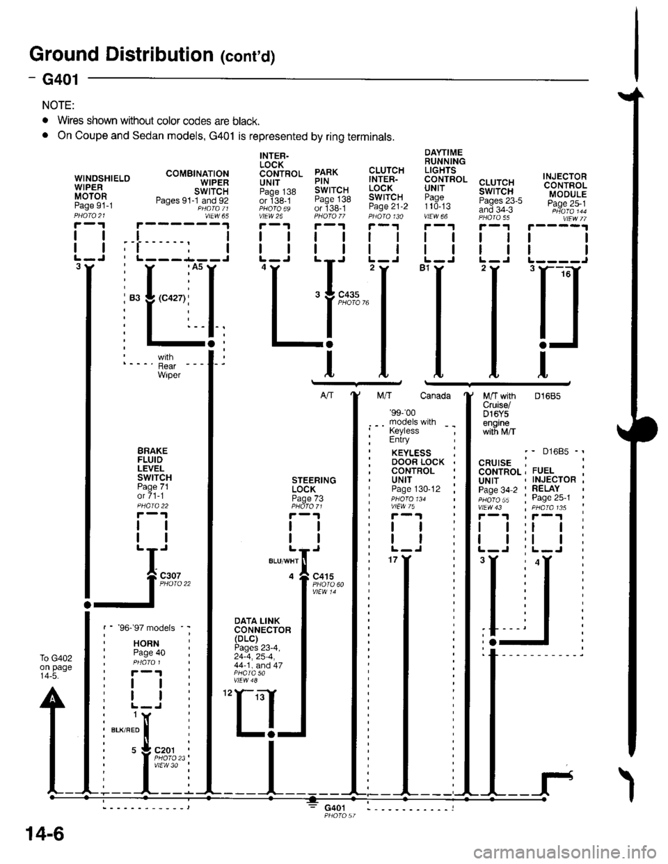
Ground Distributioh (conrd)
)
- G401
NOTE:
To G402on page14-5.
WINOSHIELOWIPERMOTORPage 91-1
DAYTIMERUNNINGLIGHTS
99.!rRoL cLUrcHuNr I swtTcH:?99^ Pases 23-5and 34-3vtEw 66 PHA|A 55
I
I
INJECTORCONTROLMODULEPage 25-1
I
I
3
. Wires shown without color codes are black.
o On Coupe and Sedan models, G401 is represented by ring terminals.
tl
tl
INTER.LOCK6611p99 PARKUN|T PINpaoe j38 SWITCHor ige_t Page 138PHoro6s of 138-1vtEw 26 PHOfO /7r-1 r-'t
tttl
CLUTCHINTER-LOCKSWITCHPage 21-2
ll
ll
ttl
rll
I
Itttl
'Ll;
I
n
t
M/T with 01685Cruise/D16Y5enginewith M/T
BRAKEFLUIDLEVELswtTcHPage 71ot 71-1
tl
tl
DOOR LOCK .CONTROLSTEERINGLOCKPage /3
tl
tl
UNITPage 130-12 ;
ttl
tt:
models
RNte 40
I
I
(
I
I czor
l'i1l?,
'97 mo
HORNPage 4
I
I
NFnl
s 9c.Plv'
BLK/RED
t
IJ;--
',f-l
DATA LINKCONNECTOR(DLC)Pages 23-4,24-4,25 4,44-1, and 47
30
14-6
G401
Page 1895 of 2189
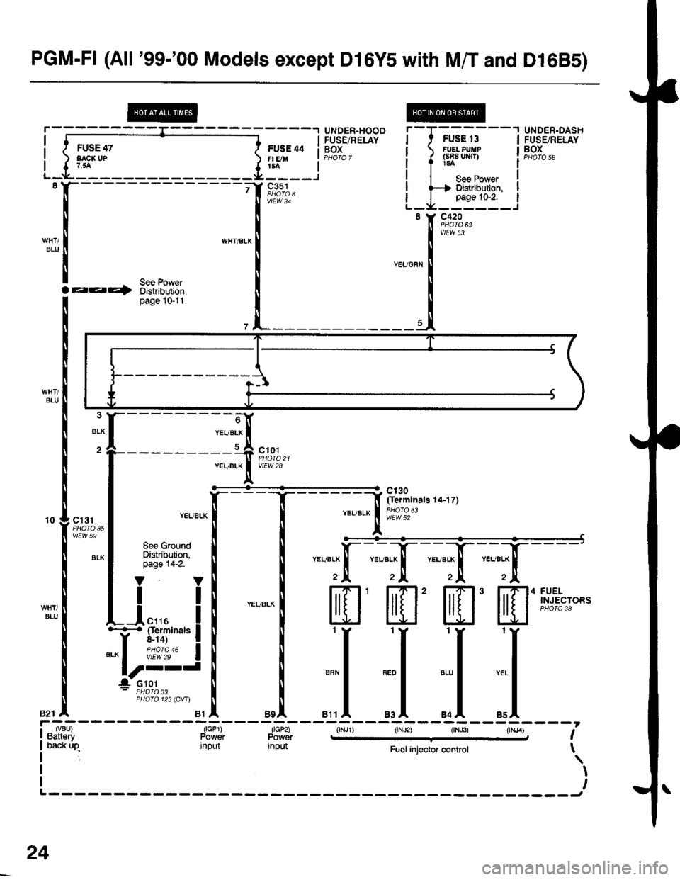
PGM-FI (All '99-'00 Models except Dl6Y5 with M/T and Dt685)
@r-T-------r UNDER.DASHI t FUSE ro IFUSE/RELAYI FUEL PUMP I BOX
i { {"rl"t* i PHarc 58
! | see Power II H Distribution. I
I I page 1o-2. IL-Y,------J8 Y C420
FUSE 44n E/ur5A
FUSE/RELAYBOX
:1,-
I
"l[-------]:"il",.,
|
'f -------;;[
#""r'6"'
ll__
il _mfil?9'"*,*,,,"f,r*r"rl"l
^*_"'l t -
I
-"1
$$f'Fl,[ I
"-Tf;f,{=l[
"rrl
Lj",,. il
"""'-l
m' m'm'm'fti:i";r""'
| *i. fl.iK""l
l I
'l
!
"'-lr4'iJ
",,,!,
+il!"'bt,"*",,N.
"j :l :l :l :l
i,rrr&---------;!%
---i*t---. ---f
I back up. input inpd Fuel injector cortrol \
t\
atL------ ______J
@
BLU
sLu
24
Page 1908 of 2189
From B
WHT/BED
WHT/REO
WHT/FED
W}ITIRED
2
c401
vlEw 73
WIIT/BED
LJ*
;.;.il,
m
:il
"u"T.l,
m
*
a
From A onfacing page.
v
I
*"rr"a^ |
,L-:l'il
mm-'
1:-a PHO|O147
I See Ground8LX I oistribtnbn,
|
*'"J'.
v'a-
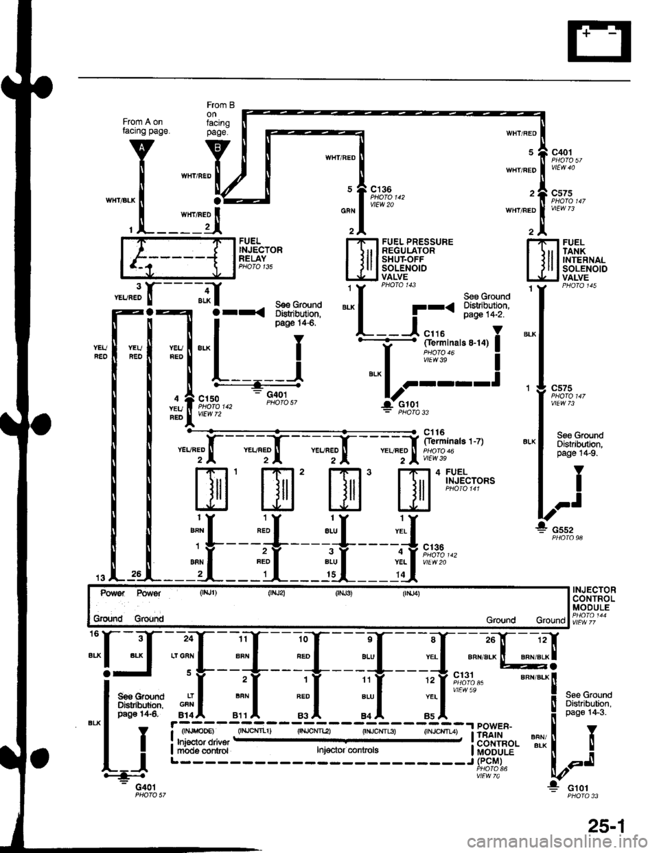
FUELINJECTORRELAYPHOTO 135
r S€s Groundarr< Dietribution.
FUEL PRESSUREREGULATORSHUT.OFFSOLENOIDVALVE
: c4o'lc150
vtEW 72
r-
IT
;.;..{
'm'
m'ill"'"-"'
,t,iJ,-,
i{
it.;:;t"'-
INJECTORCONTROLMODULE
See G.oundDislribution,pag€ 14-3.
Y
!
BFN/BLKI-J
I
I Distribr;tion,I pags r{-6.
ti: clot
y'o,JPHOIO 86
G101
-"----.< c.t 16- -J (Terminals'l-7)""'7lw;8"'"
Ground GrouftGround Ground
fu*gr PorYgrfl[J2) (rNJ3] 0NJ4]
;:[
2s-1
!-'
BFN/BLK
Page 2140 of 2189
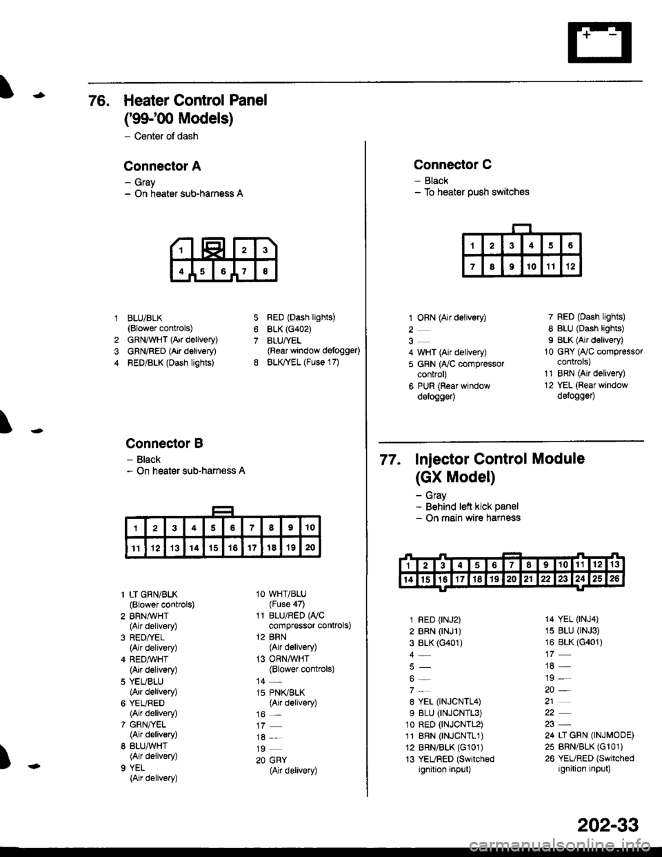
76. Heater Control Panel
('99100 Models)
- Center of dash
Conneclor A
- Gray- On heater sub-harness A
BLUi BLK(Blower controls)
GRNAVHT (Air delivery)
GRN/RED (Air delivery)
RED/BLK (Dash lights)
Connector B
- Black- On heater sub-harness A
7
8
1
4
RED (Dash lights)
BLK (G402)
BLUfYEL(Rear window defogg€0
BLK,TYEL (Fuse 17)
\
)
1 LT GRN/BLK(Blower controls)
2 BRN,A/VHT(Air delivery)
(Air delivery)
4 REDA/VHT(Air delivery)
5 YEUBLU(Air delivery)
6 YEURED(Air delivery)
7 GRN/YEL(Air delivery)
8 BLU,ryVHT(Air delivery)
9 YEL
{Air delivery)
1O WHT/BLU(Fuse 47)
11 BLU/RED WCcompressor controls)
12 BRN(Air delivery)
13 ORNAVHT(Blower controls)
14 -
15 PN(BLK(Air delivery)
16 _
19 _
20 GRY(Air delivery)
Connector C
- Black- To heater push switches
1 ORN (Air delivery)
2
4 WHT (Air delivery)
5 GRN (ry'C compressorcontrol)
6 PUR (Roar windowdelogge4
7 RED (Dash lights)
8 BLU (Dash lights)
I BLK (Air delivery)
10 GRY (Ay'C compressorcontrols)
1'1 BRN (Air delivery)
12 YEL (Rear window
defogge0
77. Injector control Module
(GX Model)
- Gray- Behind left kick panel- On main wire harness
1 RED (rNJ2)
2 BRN (rNJl )3 BLK (G401)
4_
8 YEL (TNJCNTL4)
9 BLU (TNJCNTL3)
1o RED (tNJCNTL2)
11 BRN 0NJCNTL1)12 BRN/BLK (G101)
13 YEURED (Switched
ignition input)
14 YEL (tNJ4)
15 BLU (rNJ3)
16 BLK (G401)
19 -
20-
21
24 LI GRN (INJMODE)
25 BRN/BLK (Gr 01)
26 YEURED (Switched
ignition input)
202-33
Page 2143 of 2189
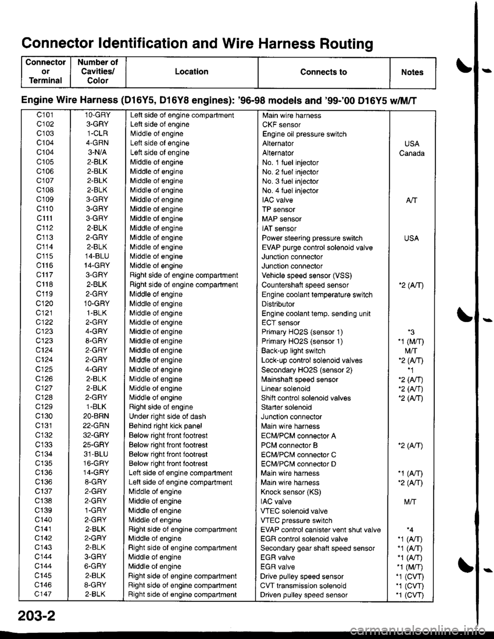
Connector ldentification and Wire Harness Routing
Connector
or
Terminal
Number ot
Cavities/
Golor
LocationConnects toNotes
Engine Wire Harness (Dl6Y5, D16Y8 engines): '96-98 models and '99;00 D16Y5 dM/T
c101
c102
c 103
c104
Q104
c105
c106
c107
cl 08
cl09
cl10
c1l1
cl'12
c113
c114
c'115
c116
c'117
c 118
c119
c120
c121
c122
c123
c123
c124
Q124
c125
c 126
c127
c128
c129
c130
c131
cl32
c 134
c135
c136
c137
c138
c139
c'140
c141
c142
c143
c144
c'|44
c145
c146
c147
1O-GRY
3.GRY
1-CLR
4-GRN
3-N/A
2-BLK
2-BLK
2-BLK
2-BLK
3-GRY
3-GRY
3-GRY
2.BLK
2.GRY
2-BLK
14-BLU
14-GRY
3.GRY
2-BLK
2-GRY
1O-GRY
1.BLK
2.GRY
4-GRY
8-GRY
2-GRY
2.GRY
4-GRY
2.BLK
2.BLK
2-GRY
1.BLK
2O.BRN
22.GRN
32.GRY
25.GRY
31-BLU
16.GRY
14-GRY
8.GRY
2-GFIY
2.GRY
1-GRY
2-GRY
2-BLK
2-GRY
2.BLK
3-GRY
6-GRY
2.BLK
8-GRY
2-BLK
Left side of engine compartment
Left side of engine
Middle of engineI att .i.la ^f an^i^6
Left side ot engine
Middle of engine
Middle of engine
Middle of engine
Middle of engine
Middle of engine
[,liddle of engine
Middle ot engine
Middle ot engine
Middle of engine
Middle of engine
Middle of engine
l\,liddle of engine
Right side of engine compartment
Right side of engine compartment
Middle ot engine
Middle of engine
Middle of engine
Middle of engine
l\,liddle of engine
Nliddle of engine
Middle ot engine
Middle of engine
Middle ot engine
Middle of engine
Middle of engine
Nliddle of engine
Right side of engine
Under right side of dash
Behind right kick panel
Below right front footrest
Below right front footrest
Below right front footrest
Below right front tootrest
Left side ot engine compartment
Left side of engine compartment
Middle of engine
liliddle ot engine
Middle of engine
Nriddle ol engine
Right side of engine compartment
Middle ol engine
Right side of engine compartment
Middle of engine
N,liddle of engine
Right side of engine compartment
Right side of engine compartment
Bight side of engine compartment
Main wire harness
CKF sensor
Engine oil pressure switch
Alternator
Alternator
No. 1 fuel injector
No. 2 fuel injector
No. 3 fuel injector
No.4 fuel injector
IAC valve
TP sensor
MAP sensor
IAT sensor
Power steering pressure switch
EVAP purge control sol€noid valve
Junction connector
Junction connector
Vehicle speed sensor (VSS)
Countershatt speed sensor
Engine coolant temperature switch
Distributor
Engine coolant temp. sending unit
ECT sensor
Primary HO2S (sensor '1)
Primary HO2S (sensor '1)
Back-up light switch
Lock-up control solenoid valves
Secondary HO2S (sensor 2)
lvlainshafl speed sensor
Lanear solenoid
Shift control solenoid valves
Starter solenoid
Junction connector
Main wire harness
ECM/PCM connector A
PCM connector B
ECM/PCNI connector C
ECM/PCl\,,| connector D
Main wire harness
Maln wire harness
Knock sensor (KS)
IAC valve
VTEC solenoid valve
VTEC pressure switch
EVAP control canister vent shut valv€
EGR control solenoid valve
Secondary gear shatt speed sensor
EGR valve
EGR valve
Drive pulley speed sensor
CVT transmission solenoid
Driven pulley speed sensor
USA
Canada
AlT
USA
'2( tr\
'3
-1 (M/r)
t\4/T'2 (Anl'1
'2 (An)'2 (Nr)'2 (AtT)
'2 (Atr)
-1 (An)-2( fi|
M/T
.1 (Arr).1 (A,T)"1 (A/r)-1 (M/r).1 (CVT),1 (cw)'1 (CVT)
203-2
Page 2145 of 2189
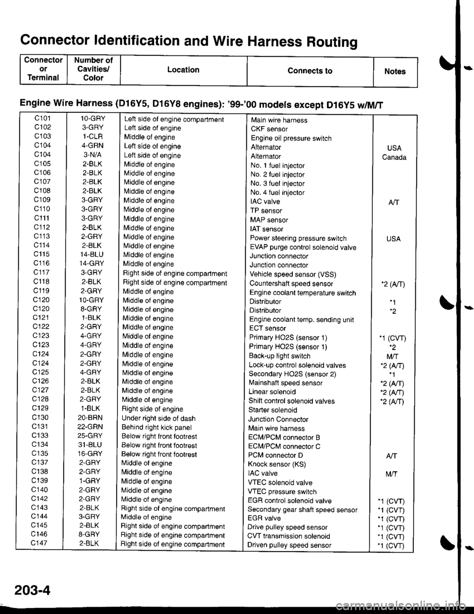
Connector ldentification and Wire Harness Routing
Connector
or
Terminal
Number of
Cavities/
Color
LocationConnects toNotes
Engine wire Harness (Dl6Y5, Dl6Y8 engines): '99-'00 models except D16y5 w/M/T
c 101
c102
c103
cl04
c104
c105
c106
c107
c108
c109
c110
c111
cl12
c1 13
c115
c117
c118
c119
c120
c120
c12'l
cl22
c123
c124
c124
c125
c126
c127
c128
c129
c130
c'131
c133
ct34
c 135
c137
c138
c139
c 140
c142
c143
c144
c'|45
c147
1O-GRY
3.GRY
1-CLR
4-GRN
3-N/A
2.BLK
2.BLK
2-BLK
2.BLK
3-GRY
3-GRY
3.GRY
2-BLK
2.GRY
2-BLK
14-BLU
14-GRY
3-GRY
2-BLK
2-GRY
1O-GRY
8.GRY,1-BLK
2.GRY
4.GRY
4.GRY
2.GRY
2.GRY
4.GRY
2.BLK
2-BLK
2-GRY
1-BLK
2O-BRN
22-GRN
25-GRY
31-BLU
16-GRY
2-GRY
2.GRY
1-GRY
2-GRY
2-GRY
2-BLK
3.GRY
2.BLK
8-GRY
2.BLK
Left side of engine compartment
Left side of engine
Middle of engine
Left side of engine
Left side of engine
Middle ot engine
Middle of engine
N,liddle of engine
l\4iddle of engine
Middle of engine
Niliddle of engine
N,,liddle of engine
Middle of engine
Middle of engine
Middle of engine
Middle of engine
Middle of engine
Rjght side of engine compartment
Right side of engine compartment
Middle of engine
Mlddle of engine
l\4iddle of engine
Middle of engine
Middle of engine
[iliddle of engine
lvliddle of engine
Middle of engine
Middle of engine
l\4iddle of engine
Middle ol engine
Middle of engine
N,liddle of engine
Right side of engine
Under right side of dash
Behind right kick panel
Below right front tootrest
Below right front footrest
Below right lront footrest
[iliddle of engine
l\,liddle of engine
Middle of engine
Middle of engine
L4iddle of engine
Right side of engine compartment
Middle of engine
Right side of engine compartment
Right side of engine compartment
Right side ot engine compartment
Main wire harness
CKF sensor
Engine oil pressure switch
Alternator
Alternator
No. 1 fuel injector
No. 2luel injector
No. 3 fuel injector
No.4 fuel injeclor
IAC valve
TP sensor
MAP sensor
IAT sensor
Power steering pressure switch
EVAP purge control solenoid valve
Junction connector
Junction connector
Vehicle speed sensor (VSS)
Countershaft speed sensor
Engine coolant temperature switch
Distributor
Distributor
Engine coolant temp. sending unit
ECT sensor
Primary HO2S (sensor 1)
Primary HO2S (sensor 1)
Back-up light switch
Lock-up control solenoid valves
Secondary HO2S (sensor 2)
Mainshait speed sensor
Linear solenoid
Shift control solenoid valves
Starter solenoid
Junction Connector
Main wire harness
ECN4/PCM connector B
ECM/PCM connector C
PCM connector D
Knock sensor (KS)
IAC valve
VTEC solenoid valve
VTEC pressure switch
EGR control solenoid valve
Secondary gear shaft speed sensor
EGR valve
Drive pulley speed sensor
CVT transmission solenoid
Driven pulley speed sensor
USA
Canada
ATT
USA
'2 (An\
'1
-1 (cw)
Mft'2 lNr)'1
'2 (Afil'2 (An)'2 (Anl
Atf
t\4/T
-1 (CVr)'1 (CVT).1 (CW)-1 (CVT)'1 (CVT).1 (cw
203-4
Page 2147 of 2189
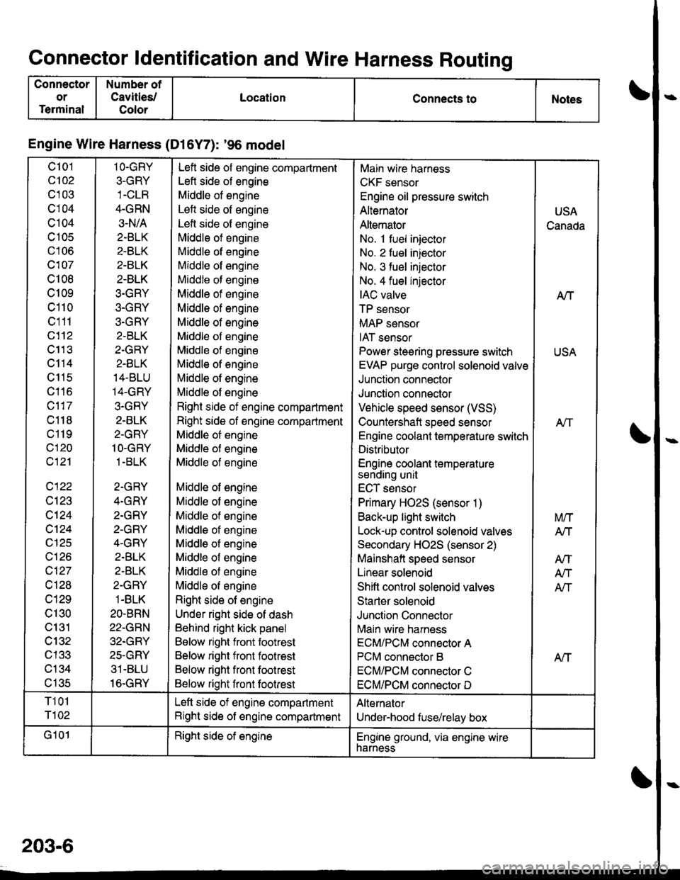
Connector ldentification and Wire Harness Routing
Connector
or
Terminal
Number of
Cavities/
Color
LocationConnects toNotes
Engine Wire Harness (Dl6Y7): '96 model
c101
c102
c103
cl04
c104
c 105
c106
c107
c108
c109
c110
c111
c112
c11 3
c114
c115
c116
c117
c118
c119
c120
c121
c122
c123
c124
cl24
c125
c126
c127
cl28
c129
c130
c131
cl32nl2?
c134al eR
1O.GRY
3-GRY
4.GRN
3-N/A
2.BLK
2-BLK
2-BLK
2-BLK
3.GRY
3-GRY
3.GRY
2-BLK
2.GRY
2-BLK
14-BLU
14-GRY
3.GRY
2.BLK
2-GRY
1O-GRY
1 -BLK
2-GRY
4.GRY
2.GRY
2-GRY
4-GRY
2.BLK
2-BLK
2-GRY
1-BLK
2O-BRN
22-GRN
32.GRY
25-GRY
31-BLU
16.GRY
Left side of engine compartment
Left side of engine
Middle of engine
Left side of engine
Lefl side of engine
Middle of engine
Middle of engine
Middle of engine
Middle of engine
Middle of engine
Middle of engine
Middle of engine
Middle of engine
Middle of engine
Middle of engine
Middle of engine
Middle of engine
Right side of engine compartment
Right side of engine compartment
Middle of engine
Middle of engine
Middle of engine
Middle of engine
Middle of engine
Middle of engine
Middle of engine
Middle of engine
Middle of engine
Middle of engine
Middle of engine
Right side of engine
Under right side of dash
Behind right kick panel
Below right front footrest
Below right front footrest
Below right front footrest
Below right front footrest
Main wire harness
CKF sensor
Engine oil pressure switch
Alternator
Altemator
No. 1 fuel injector
No. 2 fuel injector
No. 3 fuel injector
No. 4 fuel injector
IAC valve
TP sensor
MAP sensor
IAT sensor
Power steering pressure switch
EVAP purge control solenoid valve
Junction connector
Junction connector
Vehicle speed sensor (VSS)
Countershaft speed sensor
Engine coolant temperature switch
Distributor
Engine coolant temperaturesending unit
ECT sensor
Primary HO2S (sensor 1)
Back-up light switch
Lock-up control solenoid valves
Secondary HO2S (sensor 2)
Mainshaft speed sensor
Linear solenoid
Shift control solenoid valves
Starter solenoid
Junction Connector
Main wire harness
ECM/PCM connector A
PCM connector B
ECM/PCM connector C
ECM/PCM connector D
USA
Canada
A/T
USA
Atf
Aff
M/T
Arl
AtT
A/T
Afi
T101
T102
Left side of engine compartment
Right side of engine compartment
Alternator
Under-hood fuse/relay box
G101Right side of englneEngine ground, via engine wirenarness
203-6