Page 1294 of 2189

Headliner
Replacement
CAUTION: When prying with a flat-tip screwdriver,
wrap it with proioctiva tap€ to prevsnt damage.
NOTE:
. Take care not to bend and scratch the headliner.
. Be careful not to damage the dashboard and other
interior trim.
'1. Remove:
4D:
. Front pillar trim (both sides. see page 20-59)
. Center pillar lower trim panel (both sides, see page
20 59)
Upper anchor bolt from the front seat belt (both
sides, see page 20-85)
Center pillar outer trim and center pillar upper trim
(both sides, see page 20-59)
Ceiling light (see section 23)
Rearview mirror (see page 20-25)
a
a
a
a
a
3D:
. Front pillar trim (both sides, see page 20-60)
. Right rear seat-back and rear seat cushion (see
page 20-80)
. Rear center shelf (see page 20-60)
. Rear side shelf and side trim panel (right side,
see page 20-60)
. Upper anchor bolts from the front and rear seat
belts (right side. see pages 20-86, 89)
. Ouarter trim panel (right side, see page 20-60)
. Ceiling light (see section 23)
. Rearview mirror (see page 20-25)
2Dl
. Front pillar trim (both sides, see page 20-51)
. Right rear seat-back and rear seat cushion (see
page 20-81)
Side trim panel (right side, see page 20-61)
Upper anchor bolt from the front seat belt (right
side, see page 20-86)
Ouarter trim panel (right side, see page 20-6'l)
Ceiling light (see section 23)
Rearview mirror (see page 20-25)
20-64
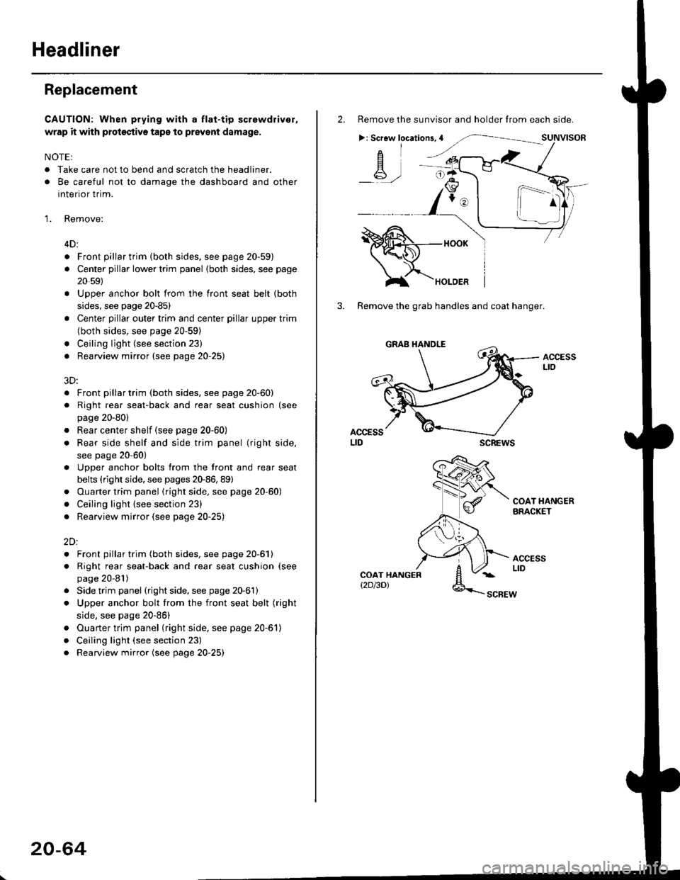
2. Remove the sunvisor and holder from each side.
>: Screw locations,4
-A-,-
3. Remove the grab handles and coat hanger.
scREws
ACCESSLto
COAT HANGERBRACKET
ACCESSLIDCOAT HANGERt2D/3DlSCBEW
1^
Page 1295 of 2189

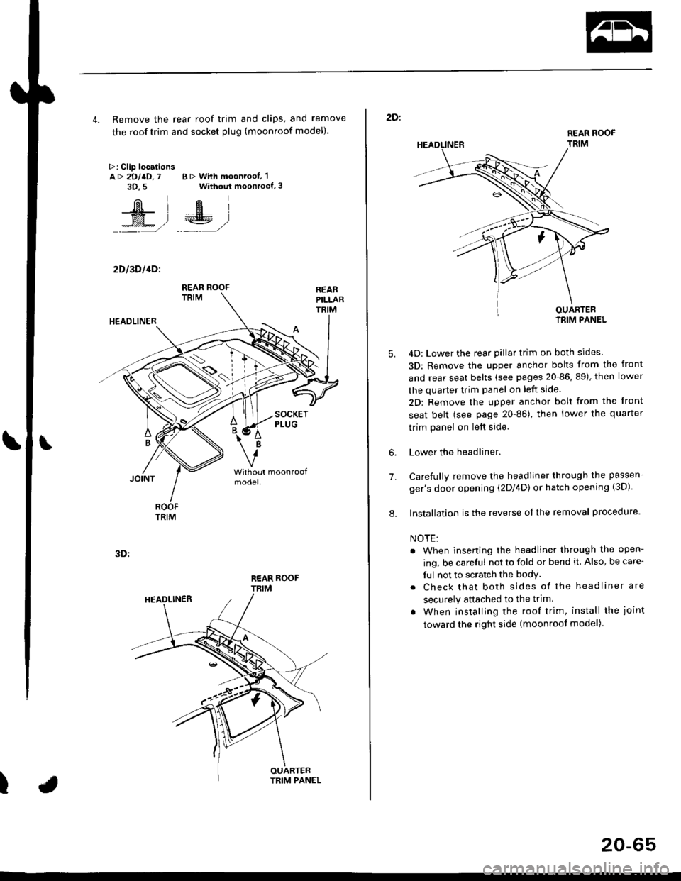
4. Remove the rear roof trim and clips, and remove
the roof trim and socket plug (moonroof model).
>: Clip locationsA> 2DllD,7 B > With moonroof, 'l
3D.5 Without moonroof,3
[il',fEl
t% .l €E .l':: =,/ _._- ,/
2D l3D l4Dl
REAR ROOFTRIM
3D:
t
REAR ROOF
TRIM
2D:
5.
7.
OUARTERIRIM PANEL
4D: Lower the rear pillar trim on both sides
3D: Remove the upper anchor bolts from the front
and rear seat belts (see pages 20-86, 89), then lower
the quarter trim panel on left side.
2D: Remove the upper anchor bolt from the front
seat belt (see page 20-86), then lower the quaner
trim panel on left side.
Lower the headliner.
Carefully remove the headliner through the passen-
ger's door opening (2Dl4D) or hatch opening (3D).
Installation is the reverse of the removal procedure.
NOTE:
. When inserting the headliner through the open-
ing, be careful not to fold or bend it. Also, be care-
ful not to scratch the bodY.
. Check that both sides of the headliner are
securely attached to the trim.
. When installing the roof trim, install the joint
toward the right side (moonroot model)
6.
8.
20-65
Page 1303 of 2189
Seats and Seat Belts
Component Location Index
2Dl3Dl1Dl
SHOULDER ANCHOR
ADJUSTER (4D)
(see Page 20-85i
FRONT SEAT BELT
Replacement, Pages 20 85,86
Inspection, Page 20-91
FRONT SEARemoval, Page 20'74
Replacement, Page 20 75
Harness Wiring and Recline
Cable Locations, Page 20-77
Seat Cover RePlacemenl, Page 2O'77
3D:
BEAR SEAT BELTReplacement, Page 20'89Inspection, page 20-91
REAB SEAT BELT (2DI4DI
Replacement, page 20-88
lnspection, page 20-91REAR SEAT EELT BUCKLE/CENTER BELT TONGUE (2DI4DI
(see p6ge 20'90)
REAR SEAT t2Dl4DlRemoval, pages 20-79, 8'l
Seat-back Latch Replacement, page 20-82
Seat Cover RePlacement, Page 20-83
FRONT SEATBELT BUCKLES{see page 20-87)
REAR SEAT BELT BUCKLE/
CENTER BELT TONGUE(see Page 20'90)
REAR SEATRemoval, page 20 80
Seat back Latch Replacement, page 20-8?
Seat Cover RePlacement, Page 20_83
20-73
Page 1305 of 2189
Replacement
CAUTION: When prying with a flat-tip screwdrivet, wrap it with protective tape to prevent damage'
NOTE:
. Take care not to scratch the seat covers and body
. Remove the front seat through the door openlng'
Driver's:
NOTE: Refer to page 2O-77 for the seat belt switch harness wiring location'
SEAT CUSHION
CENTER COVER
INNER SEATTBACK
PIVOT NUT8 x 1.25 mm22 N.m l.2.216 tbf.ft)
v
l
35 tbt.ft)
10 x 1.25 mm47 N.m {4.8 kgf m,10 x 1.25 mm47 N.m {i1.8 kgl m,35 tbr.ft)
RECLINE ADJUSTER
LOW
d
ER CAP
l
RECLINE
CONNECTING WIRETo connect, twist 180'
OUTER SEATTRACK
Installation is the reverse of the removal procedure'
NOTE:
. Make sure the bushing and pivot washer
installed ProPerly.. To prevent wrinkles when installing the seat-
back cover, make sure the material is stretched
evenly over the Pad.
. Grease the sliding Portion
8 x 1.25 mm20 N.m 12.0 kgf.m,14 tbt.ft)
are
RECLINEKNOB
(cont'd)
20-75
10 x 1.25 mm47 N.m {4.8 kgf'm,35 tbtftl
Page 1306 of 2189
Front Seat
Replacement (cont'd)
Passenger's (with reclino cablel:
NOTE; Refer to page 20-77 for the recline cable location.
HEADREST
PIVOTWASHER
LOWERCAP
PIVOT NUT8 x 1.25 mm22 N.m 12,2 kgl.m,tbt.ftt
SEAT CUSHION
CENTER COVER
10 x 1,25 mm47 N.m (4.8 kgf.m,
10 x 1.25 mm47 N.m {4.8 kgf.m,3s tbt.ft)
INNER SEATTRACK
35 tbf.ftl
RECLINE ADJUSTEB
RECLINECOVER
i LowER CAP
bRECLINECABLE
x 1.25 mm47 N'm (4.7 kgf.m,35 tbtftl
SEAT
8 x 1.25 mm20 N.m {2.0 kgf.m,14 rbf.ft)
ruf, To connect, twist 180'.
lnstallation is the reverse of the removal procedure.
NOTE:
. Make sure the bushing and pivot washer are
installed properly.
. To prevent wrinkles when installing the seat-back
cover, make sure the material is stretched evenly
over the pad.
. Adjust the recline cable.
. G.ease the sliding ponion.
SEAT-BACK
20-76
Page 1307 of 2189
Harness Wiring and Recline
Cable Locations
NOTE: When installing the seat cushion, make sure the
seat belt switch harness, connector and recline cable are
fastened correctly on the seat cushion frame'
Driver's:>: Clip locations
Passenger's (with lecline cablel:
TRACK
Seat Cover RePlacement
CAUTION: Put on gloves to protest yout hands'
NOTE: Take care not to tear the seams or damage the
seat covers.
Seat-back cover removal:
1. Release the hook, and fold back the seat-back cover'
Release all inside springs, then fold back the seat-
back cover.
Remove the headrest.
Remove the headrest guide, then remove the seat-
back cover.
lnst;llation is the reverse of the removal procedure'
NOTE: To prevent wrinkles when installing a seat-
back cover, make sure the material is stretched evenly
over the pad before securing the inside springs and
hook.
3.
(cont'd)
20-77
HEADREST
Page 1344 of 2189
Windshield Wiper Arms and Linkage
Replacement (cont'dl
USA-produced:
3. Separate the windshield wiper linkage and wind-
shield wiper motor.
Japan/Canada-produced:
NOTE: Scribe a line across the link and windshield
wiper linkage to show the original adjustment.
>: Bolt locations, 3
O 6r1.0mm
EF 8 N.m {0.8 kstm,ig 5.8 tbf.ft) )
NUT10 x 1.25 mml8 N rn (1.8 kgtm,13 tbtftl
>r Bolt locations,3
WIPER LINKAG€
\
20-114
USA-produced:
NOTE: Scribe a line across the link and windshield
wiper motor to show the original adjustment.
>: Bolt locations, 2
R 6J( 1.0 mm
Y 8 N.m to.s kgtm, I
.E- 7Y.nt )
NUT10 x 1.25 mm'18 N.m {1.8 kgf.m.13 tbtft)
WINDSHIELDWIPER MOTOR
4. Installation is the reverse of the removal procedure.
NOTE:
. Make sure the connector is connected properly.
. lf necessary, replace any damaged clips.
. lnstall the windshield wiper arms as described
on page 20-1'17.
. Check the windshield wiper motor operation.. Grease the moving parts.
Page 1352 of 2189
Body ('97 model)
Front Seat Belt
Removal/lnstallatlon ....20-128
Rear Seat
RemovaUlnstallation ....20-126
Washer Tube
Windshield
fndex .......... 20-124
Outline of '97 Model Changes
The molding side seal was added.
The method of installing the rear seat cushion was changed (2Dl3D).
A middle floor gusset was added and the method of detaching the seat belt retractor was changed (2Dl3D)
The installation position of the washer tube was changed.