Page 1937 of 2189
A/T Controls ('99-'00 CVT) (cont'd)
)a
Y,
!@
Sa€ POM-FI,page t4€-
YEUBU,I
THROTTLEPOStTtON
FP)SENSOR
\
lt
tl
tt
tt
A9
I
I
I
IL
A8
1
S€€ GrdJrdDisthutlon,pagg 14-7.
c410
vtEw s5
c13 tPHO|O A5vtEw 59
AL
-'r PowERTRAtN' I coNrBoL-. I MODULE (PCM):, I PHO|O 86| | vtEw 70
H$,{srt | ffiffir*Hl
.rud":[4:l
-
;i ",,1 ",[.,,[ ;['
i
- -*j;- -F- - -:m;
lmr
- - -
;'ril)-I ground s€nsor ground sansof indicator
I inp.,t input contml
L------
I
E
F
t,
10 Y c50t"..1if?!o..6.o,
i-=1ffifiI"'""'3**",
I --+;;ai*r
YELI 33:$:?AX'."
^,I xI
-HI-
I F-J---L---J---, f
ir rI
i i I Dtmmhg chcutr I I t
ii.-----r--.,1, tl
ii 6-l \
39-14
Page 1939 of 2189
Horn
- '96-'97 Models
UNDER.HOODFUSE/RELAYBOX
c353PHOTOs
See PowerOistribution,pag610-13.""^T.!,-
HORNRELAYPHA|O 58
c214
vtEw21
BLU/FEO
1
VHT/qRN
I1
WHT/qRN
: :i-I:::--li i ! !'-'! fevtess
! a;fi."*
,,lr--J I::.-------J. , STEREO RAOIO TUNER
| | vtEw 68
HORN
l
h: c4o1PHQ|A 57
c430
Sse CruiseControl
Vehicles pre-wired ---lor accessorysecurity system
BLU
GBY
------- J
- -.! STEERINGWHEEL
6 g c411
| _vtEw 60
a,---li
cnv I
18 A C516
sEcuRtwSYSTEMCONNECTOR(oPTroN)PHO|O 73VEW 5A
40
Page 1944 of 2189

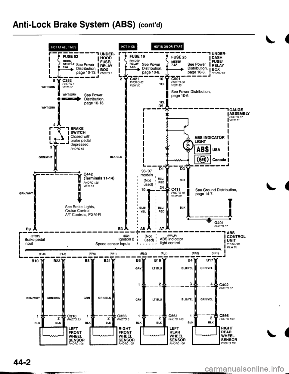
Anti-Lock Brake System (ABS) (cont'd)
(
FUSE 16iA DEFlEtsY See Power:ar Distribution,page 10-8.
c421 10
vlEW 50
'96- 97 Dl
mooels
.I UNDER-
page 1G6. I pHoro 5d
c501
vlEW 55
See Power Distribution,page 1S6.
AAS INDICATORLIG}IT
!'-r;us?;---l H5BE"
ilrryilrfi#ftilHriL-g------JL-g------J'tr F,1%'wHr/GRN I v/El.V 2Z
I t"r,o"" se€ Power
YELD5GAUGEASSEMBLY
usA
CarsdaI
(
D3
', ',i:,tr?""" ! P"g" t+-z".r',
*
! see cround Distributiofl,
".., I i"., I ".-l I;nl
iffit L------J
' n : G401
mI iot
T1*l ^*ry*l:-------l 8Bi"o.' used) ; 4ts5lnolcalor i UH|Tr----j. light conlrol r. iicib ett,"LTfflo",Input
1lo2)lgnition 2
Speed sensor anputsvlEw 63
(
{FLo) {FL1) (FBo) {FF1) (Rr"o) Sg____gT]-__g,l-j
Blo lf B23Y B8Y B21lf B6Y BlsY B4X B17f
i i I i o""l .,",-ul u.,"..1 o"",'.. I
rrttl
| | | I ,l ,l .I of"on"
ll ll I ti
't---'+----"[ --f !'?'%,'
""n*",lo"no""l *"1 *"*-l *"1 .'"."1 *,*.[ "**.I
I r L___t"" " t__t"." 1___!".""
"r.f_ "4::3' ;FJ,;::; ":f3:::1'' "lf-*i":''
t' ,.,Jtri"?r. ll;l]flffi lFli.ft. lU]flqtfl
l l"#tgl I lt5T8?l I lt"F"Ti?l I lt;Tt?f
O--t Distribution,
'n"r,o^n
I
Page 10-13'
.trr -N- .I BRAKE
| | swrrcH
igr:*
o"ntr"r
!
a'KBLU
It
""*[:-l
ftff^"n"o''''ot
I
", I
m;r""#,usi:",
".1
44-2
Page 1946 of 2189

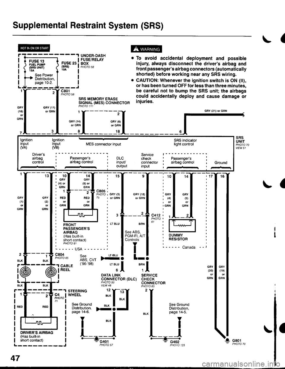
Supplemental Restraint System (SRS)
(
FUSE 13FUELPUUPFBA UMT)15A
See PowerDistibution,page 10-2.
FUSE 23(sRs)
c801PHOTO 58
SRS MEMORY ERASESTGNAL (MES) CONNECTORPHO|O 111
. To avoid accidental deployment and possible
iniury always disconnect the driver's airbag and
f ront passenger's airbag connectors (automatically
shorted) before working near any SRS wiring.
. CAUTION: Whenever the ignition switch is ON (tt),
or has been turned OFF for less than three minutes,
be caretul not to bump the SRS unit; the airbags
could accidentally deploy and cause damage or
iniuries.
UNDER-DASHFUSE/RELAYBOX
GFY 07)or GFN{18)
GFN
GFYt2l
GFN
GRY0)
GFN
2
ALK
J (ii
t\
GFY O4)or GRN
SRSUNIT
a
-ffiffi,*l-{
H!=";=_J
iffii'r:fi:*" i tH-
PHOIO 125short contact) | - FCqOtL_________J PHO|A 57
47
GAY (21) or GRN
lgnitionInput(VA)
Driver's
cont.ol
lgnitioninput(VB)MES connector inputSRS indicatorlighl control
Service t------check : Passengefs ;connector ; airbag control , GroundInpu , /+rr I pir-r
Passenger'sai|bag conlrol; prc..t rnpuv, Ourpul
14GRY(5) orGFN
rffi{{_ilil
i ffi i""'"1*"o,"'.1'' i lffil
ffirtu!-T:l
ir:r*::"."
ilstEl'{s6.e8'�
'"'Jl "Tl
, I oATA L|NK SERVTCE: CoNNECTOR (DLC) CHECK,J piarasa CONNECTORvtEw48
Page 1949 of 2189
- '99-'00 Models
i-F;;t
L-t'::-i
"d[ft?"l'
UNDER.HOODFUSE/RELAYBOX
UNDER-DASHFUSE/RELAYBOXPHOTO 58
iGi'i'-----'lBEATEA,'/C RE|AY7.5A
".*1.[F*ft"
See PowerDist.ibution,
FUSE 55HEAIERt/toToR
page 10"9.L-*----::--J
BLU
n
$
Se€ PowsrDl8tdbution,pago 1O11.
g€e PowsrDlslribution,pag€ lGg,
ALOWEFmoToRREIAYPHOTO Il1
BIUBLIVYEI
813
OFN/WHT
BLK
2BIK
G402G402
"lSi:lf:::' >-1
-".. i c.u, I--';-lP;!o;i: I---------J
l ,f 3ffJ?il3'o'"o'o*'on
L __ f_---_-_ :::::: - --- r-- -- J
-f-***;
;Iru
I 'rr l-'n BLowER---:-----.l I A lm-o-roC'------------a---E eaoz - I( M rlProraE3PHoro 12s I Y I=----GG-a -
vtEvl 57c440
Se€ Ground
".","i-l'
Ea
JI
6BLOWERMOTORTIIGHRELAYPHO|O 83
UNDER.HOOOFUSE/RELAYBOX
t
!.-
1 HEATER I"-'FI POWERt Battory lgnition Blower I CONTROL I | | rAlHStStOni (brckup) input molor i pAHel I I I pHoro 13e
I ,,o*", _ ffJtt' t PHoro tr7 | tt I
i motor Power ' 'Jback I wr'vzo
I ;_ |! high relay transislor
Ls::s1gl-tt:---J lJ J I
A6
alK
See GroundOistribution,page '14-5.
za
60-1
Page 1952 of 2189
![HONDA CIVIC 1999 6.G Workshop Manual Air Delivery
- 99-00 Models
a
r--T----.I UNDER-HOOD UNDEB-DASH
| ,ry:i.l? IFUSE/RELAY I t::u:E^tt l:usE/RELAyi
- -{-;;; -
I PJ,.,8.J390 i
-
T;; ;
- - - - -
I H$3,,8
i 1;:t"* ];FPJ", i i m. HONDA CIVIC 1999 6.G Workshop Manual Air Delivery
- 99-00 Models
a
r--T----.I UNDER-HOOD UNDEB-DASH
| ,ry:i.l? IFUSE/RELAY I t::u:E^tt l:usE/RELAyi
- -{-;;; -
I PJ,.,8.J390 i
-
T;; ;
- - - - -
I H$3,,8
i 1;:t"* ];FPJ", i i m.](/manual-img/13/6068/w960_6068-1951.png)
Air Delivery
- '99-'00 Models
a
r--T----.I UNDER-HOOD UNDEB-DASH
| ,ry:i.l? IFUSE/RELAY I t::u:E^tt l:usE/RELAyi
- -{-;;; -
I PJ,'.',8.J390 i
-
T;; ;
- - - - -
I H$3,',8
i 1;:t"* ];FPJ", i i m'.u" se€power i "t8L,,
i t i a l'"0 r3l",lli"i:" aL--{..-----J L-J..----5::---:-J
"",":"rfi?ll, '[r;T:1"
-",*"1-J
*-*..l
,n", ".u I lt I
lr !I See Power I See Power Distnbution.I Distribution, U page 1o-9.
,, L::':l------- *Y=l
"*o "."",,t
[
*,:.'.Y%
Irel-
lt
:'l-4riffi
MODECONTROLMOTOR
;L:L{;I{,tt't{ {f
SensorGround grgund
venl
Air mix5Y poientia,reTgrano9 rnrrul
gIouno
RecircSwilcfi switchcommon mput
Recirc S$,itchtED LEDcontrol common
RECIRCULATIONCONTROLMOTORPHOTO 139
CONTROLPANEL
vtEw 76
So€ Roar II Windolv :
a
Htr Ttr =tr ;l *tr :tr *,tr THtr Ttr =tr ;l *tr :tr *tr Ttr
'il
Ti
Battery lgnition Mod€ Mode Mode L4ode Mode l od€(back up) input detrost h€av heat heav vent motorR€circulato Fresh
IJ
Delogger
L------- ---J
HEATERPUSHswtTcHEs
delrost
Air Airmix mixcool hot;;-; J'J - - - J-JL i- 5:- - -
SLK
812
AFN
13
BFN
See GroundDistribution,page 14-5.
c4 t, cl
WHT I ONN
ft++il
c723
F ash/RoclreSwftch
Reclrc.oat LEo
IY
tt
L__l--tGo3,
See RearWindowOetogger
AIR MIXTURECONTROLMOTOR
(
c9 Y cl1
61-2
Page 1954 of 2189
A/C Compressor Controls
- AllModels
cc5)M7
BLU/RED
?
\a
@
&cCOMPRESSORCLUTCHRELAYPHOfO 10
a
! ,acc, : POWERTRATN! arn.^-^,o..^, I or ENGINE
! ii i"i-iiii"v i.,ii.r | fi 3$18.
I A/C request ! (pCM or ECM)I (ACSJ a pHOrO a6L------J vtEw 70
REO
BEO
1
RED
BLU/FEO
2
BLU/FEO
ct31
:"1'!i'------;
Fi:rz, a ='e6-'s8: A|| moders except D1685vtEw 21 '99100: D16Y5 with l\illT'* = 96-'98: All models
ir'iio ," 99. 00: Dt6y5 wth t\4/t Dl6Bb
atcPRESSUREswtTcH
c752
c1
".,n""t 1(
".r-".rf, "tA% "
"."-:,fi tfr,]4.
v
To facing page ('96''98 models)or page 62'2 ( 99-'00 models).
-Yl
-t---------Jc353
c2'14
vtEW21
c209
A,/CCOMPRESSORCLUTCH
COMPRESSORTHERMALPROTECTOR
UNDER-HOODFUSE/RELAYBOXf-T-*-'.T'---l H53.',EPA?' i-l-------
i iflH* !F,?r",, i f6F"'.i:.",",
| tsBi":J;"#il ! a T| | oaoe 1o-9. ! I I See PowerL_J1_j:_-_j ! H Distriburion.e Y c42o i I
pase 1o-1.
***
f ifi"l'
^ see power ! |
62
!(on bracket)
Page 1957 of 2189

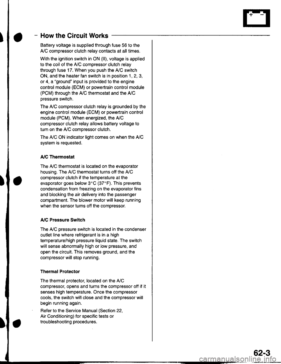
- How the Circuit Works
Battery voltage is supplied through tuse 56 to the
A,/C compressor clutch r€lay contacts at all times.
With the ignition switch in ON (ll), vollage is applied
to the coil of the A,/C compressor clutch relay
through fuse 17. When you push the A,/C switch
ON, and the heater fan switch is in position | , 2, 3,
or 4, a "ground" input is provided to the engine
control module (ECM) or powertrain control module
(PCM) through the l'lC thermostat and the l'lC
pressure switch.
The A,/C compressor clutch relay is grounded by the
engine control module (ECM) or powertrain control
module (PCM). When energized, the A'lC
compressor clutch relay allows battery voltage to
turn on the A,/C comDressor clutch.
The A,/C ON indicator light comes on when the A,/C
system is requested.
A,/C Thermostat
The A'lC thermostat is located on the evaoorator
housing. The A,/C thermostat turns off the A,/C
compressor clutch if the temperature at the
evaporator goes below 3'C (37'F). This prevents
condensation from freezing on the evaporator fins
and blocking the air delivery into the passenger
compartment. The blower motor will keep running
when the sensor turns off the comDressor.
A,/C Pressure Switch
The fuC oressure switch is located in the condenser
outlet line where refrigerant is in a high
temperature/high pressure liquid state. The switch
will sense abnormally high or low pressure, and
open the circuit. This removes ground, and the
compressor will stop running.
Thermal Protectot
The thermal protector, located on the A,/C
compressor, opens and turns the compressor off if it
senses high temperature. Once the compressor
cools, the switch will close and the compressor will
begin running again.
Refer to the Service Manual (Section 22,
Air Conditioning) for specific tests or
troubleshooting procedures.
62-3