1999 HONDA CIVIC dash
[x] Cancel search: dashPage 2127 of 2189
Connector Views (cont'd)
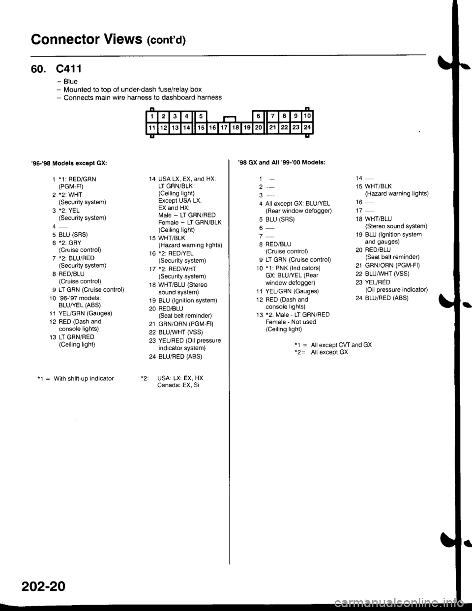
60. c411
- Blue- Mounted to top ol under-dash fuse/relay box- Connects main wire harness to dashboard harness
'95198 Models excepl GXI
1 *1: RED/GRN(PGrvr-FD
2 A2: WHT(Security system)
(Security system)
4
5 BLU (SRS)
6 *2r GRY(Cruise control)
7 *2: BLU/RED(Security system)
8 RED/BLU(Cruise control)
9 LT GRN (Cruise control)
10 '96-�97 models:BLU/YEL (ABS)
11 YEUGRN (Gauges)
12 RED (Dash andconsole lights)'13 LT GRN/RED(Ceiling light)
*1 = With shitt-up indicator
14 USA LX, EX, and HX:LT GRN/BLK
{Ceiling light)Except USA LX,EX and HX:ftrale - LT GRN/REDFemale - LT GRN/BLK(Ceiling light)
15 WHT/BLK(Hazard warning lights)
16 *2: RED|YEL(Security system)
17 *2: REDA/VHT(Security system)
18 WHT/BLU (Stereo
sound system)
19 BLU (lgnition system)
20 RED/BLU(Seat bett reminder)
21 GRN/OBN (PGN4 FD
22 BLUAVHT (VSS)
23 YEURED (Oil pressure
indicator system)
24 BLU/RED (ABS)
USA: LX: EX, HXCanadar EX, Si
202-20
'98 GX and All '99-'00 Models:
1
2
4 All except GX: BLU/YEL(Rear window defogger)
5 BLU (SRS)
7
B RED/BLU(Cruise control)
9 LT GRN {Cruise control)
10 *1: PNK (lnd cators)GX: BLU/YEL (Bear
window defo9ger)
1l YEL/GBN (Gauges)
12 RED (Dash andconsole lights)
13 *2: Male - LT GRN/REDFemale - Not used(Ceiling light)
14
15 WHT/BLK(Hazard warning lights)
18 WHT/BLU(Stereo sound system)
19 BLU (lgnition systemano gaugesl
20 RED/BLU(Seat bell reminder)
21 GRN/ORN (PG[,4-Fl)
22 BLU,ryVHT O/SS)23 YEURED(Oil pressure indicator)
24 BLU/RED (ABS)
*1 = Allexcept CW and GX*2= All except GX
Page 2130 of 2189
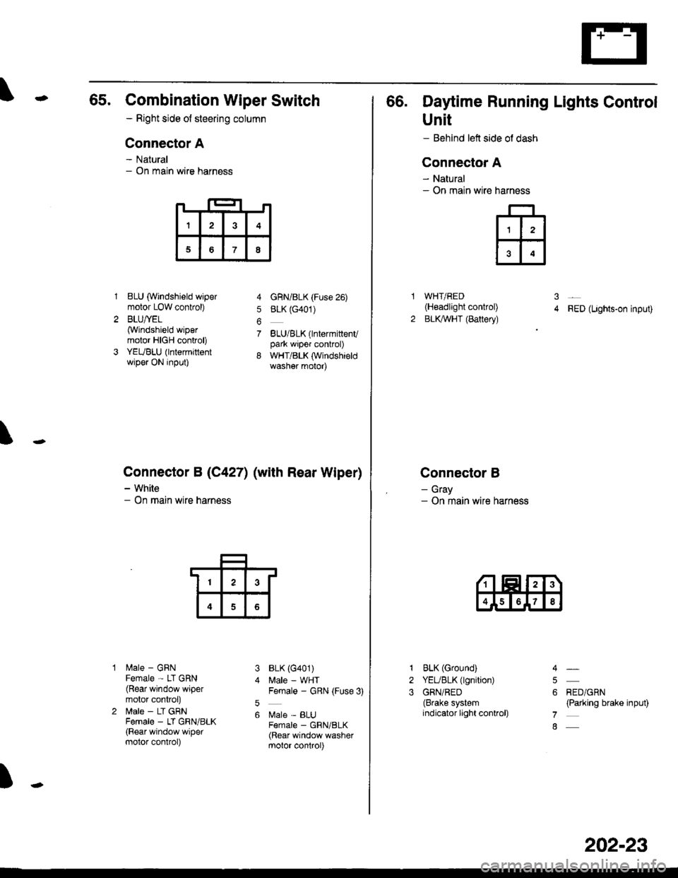
65. Combination Wiper Switch
- Right side ot steering column
Connector A
- Natural- On main wire harness
1BLU (Windshield wipermotor LOW conkol)
BLU/YEL(Windshield wipermotor HIGH control)
YEUBLU (lntermittentwiper ON input)
lilale - GRNFemale - LT GRN(Rear window wipermotor conkol)
lrale - LT GRNFema|e _ LT GRN/BLK(Rear window wipermotor control)
4 GnN/BLK (Fuse 26)
5 BLK (G401)
7 BLU/BLK(lntermittenvpark wiper control)
8 WHT/BLK (Windshieldwasher motor)
BLK (G401)
Male - WHTFemale - GRN (Fuse 3)
Male - BLUF€male _ GRN/BLK(Rear window washermotor control)
\
Connector B (C4271 (with Rear Wiper)
- White- On main wire harness
3
5
6
)
I3
68
13
4
66. Daytime Running Lights Control
Unit
- Behind left side ol dash
Connector A
- Natural- On main wire
WHT/RED(H€adlight control)
BLKAVHT (Battery)RED (Lights-on input)
Connector B
- Gray- On main wire harness
narness
ffi
31
2
1
2
3
BLK (Ground)
YEUBLK (lgnition)
GRN/RED(Brake systemindicator light conkol)
RED/GRN(Parking brake input)
4
5
6
7
8
202-23
Page 2131 of 2189
Gonnector Views (cont'd)
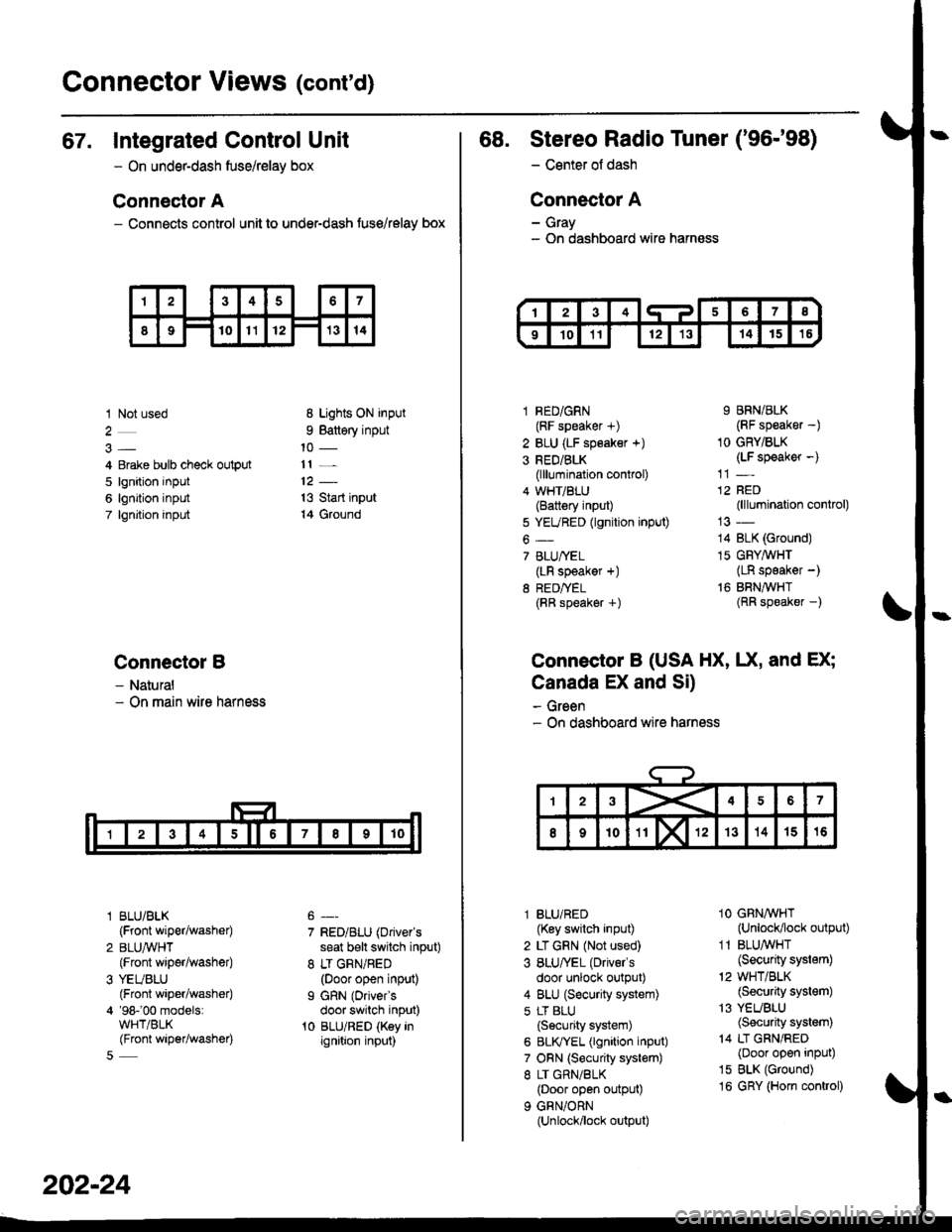
67. Integrated Control Unit
- On underdash fuse/relay box
Connector A
- Connects control unit to under-dash fuse/relay box
1 Not used
4 Erake bulb check output
5 lgnition input
6 lgnition input
7 lgnjtion input
Connectol B
- Natural- On main wire harness
l BLU/BLK
{Front wiper/washer)
2 BLUA/VHT(Front wiper/washe0
3 YEUBLU(Front wiper/washer)
4 '98-'00 models:WHT/BLK(Front wiper/washer)
8 Lights ON input
9 Battery input
11 _
13 Start input
14 Ground
7 RED/BLU (Driver's
seat b€lt switch input)
8 LT GRN/RED(Door open input)
I GRN (Oriver's
door switch input)'t0 BLU/RED (Key inignition input)
202-24
68. Stereo Radio Tuner ('96-'98)
- Center ot dash
Connector A
- Gray- On dashboard wire harness
1 RED/GRN(RF speaker +)
2 BLU (LF speaker +)
3 RED/BLK(lllumination control)
4 WHT/BLU(Battery input)
5 YEURED (lgnition input)
6-
7 BLU/YEL(LR speaker +)
8 RED/TEL(RR speaker +)
9 BRN/BLK(RF speaker -)
1O GRY/BLK(LF speaker -)
12 RED(lllumination control)
14 BLK (Ground)
15 GFY,4/VHT(LR speaker -)
16 BRNAVHT(RR speaker -)
Connector B (USA HX, UX, and EX;
Canada EX and Si)
- Green- On dashboard wire harness
l BLU/RED(Key switch input)
2 LT GRN (Not used)
3 BLU/'EL (Drivels
door unlock output)
4 BLU (Security system)
5 LT BLU
{Security system)
6 BLIVYEL (lgnition input)
7 ORN (Security system)
8 LT GRN/BLK(Door open output)
9 GRN/ORN(Unlock/lock output)
1O GRNAVHT(Unlock/lock output)
1 1 BLU/WHT(Security system)
'2 WHT/BLK(Security system)
13 YEUBLU(Security system)
14 LT GRN/RED(Door open input)
15 BLK (Ground)
16 GRY (Horn conkol)
Page 2137 of 2189
Connector Views (conrd)
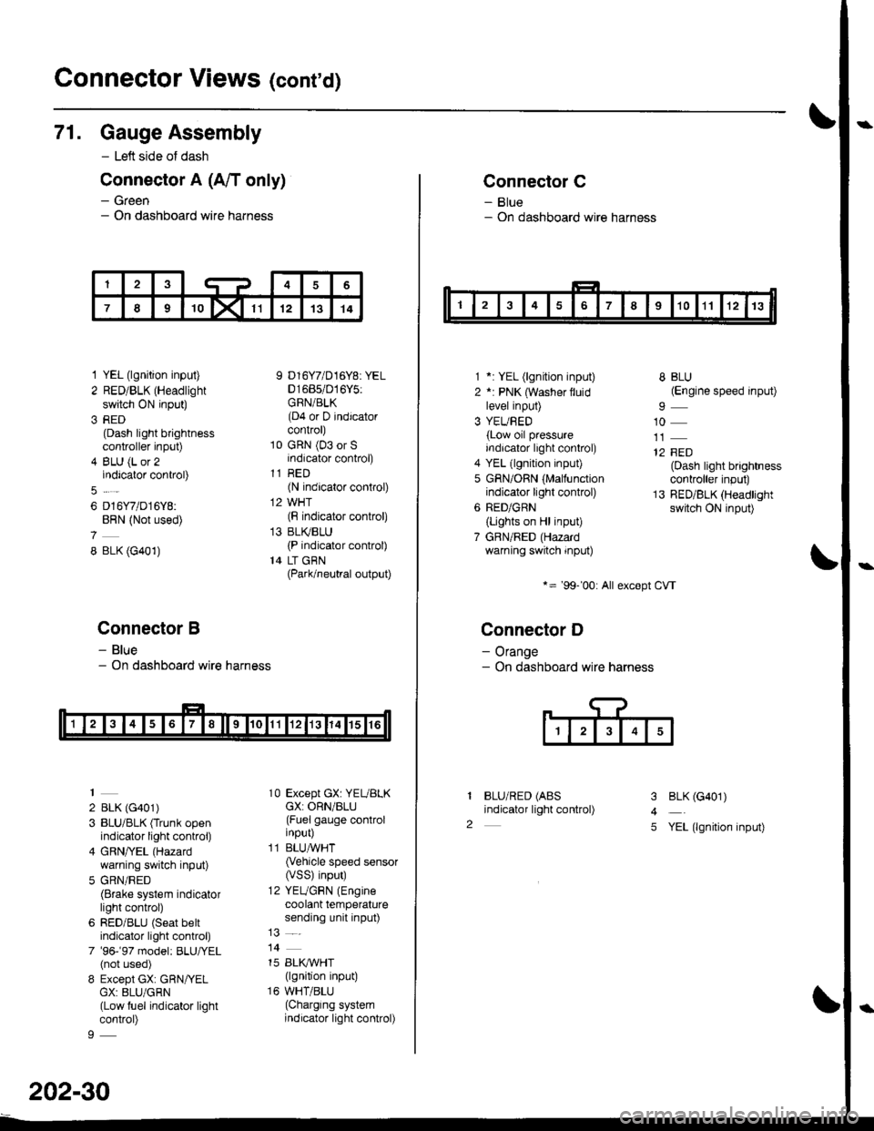
71. Gauge Assembly
- Left side of dash
Connector A (A/T only)
- Green- On dashboard wire harness
1 YEL (lgnition input)
2 RED/BLK (Headlight
switch ON input)
3 RED(Dash light brightnesscontroller input)
4 BLU (L or 2indicator control)
6 D16Y7/D16Y8:BRN (Not used)
8 BLK (G401)
Connector B
- Blue- On dashboard wire harness
2 BLK (G401)
3 BLU/BLK (Trunk openindicator light control)
4 GRN/YEL (Hazard
warning switch input)
5 GRN/RED(Brake system indicatorlight control)
6 RED/BLU (Seat beltindicator light control)
7 '96-'97 model: BLU,ryEL(not used)
8 Except GX: GRN/YELGX: 8LU/GRN(Low fuel indicator lightcontrol)
9 D16Y7/D16Y8: YEL01685/016Y5:GRN/BLK(D4 or D indicatorcontrol)
10 GRN (03 or Sindicator control)
11 RED(N indicator control)
12 WHT(F indicator control)
13 BLI(BLU(P indicator control)
14 LT GBN(Park/neutral output)
10 Except GX: YEUBLKcX: ORN/BLU(Fuel gauge controlinput)
11 BLUAVHT(Vehicle speed sensor(VSS) input)
12 YEUGRN (Engine
coolant temperaturesending unit input)
14
15 BLI(IVHT(lgnition input)
16 WHT/BLU(Charging systemindicator light control)
202-30
Connector C
- Blue- On dashboard wire harness
1 *: YEL (lgnition input)
2 *: PNK (Washer lluidlevel input)
3 YEUBED(Low oil pressureindicator light control)
4 YEL (lgnition input)
5 GRN/ORN (Malfunctionindicator light control)
6 RED/GRN
{Lights on Hl input)
7 GBN/RED (Hazardwarning switch input)
*= '99-'00: All except CVT
Connector D
- Orange- On dashboard wire harness
BLU/RED (ABS
indicator light control)
8 BLU(Engine speed input)
10
12 FED(Dash light brightnesscontroller input)
13 RED/BLK (Headlightswitch ON input)
I
2
3
4
5
BLK (G401)
YEL (lgnition input)
Page 2138 of 2189
\
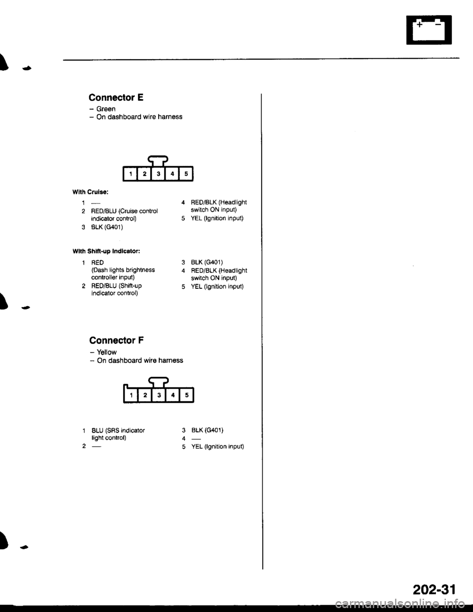
Connector E
- Groen- On dashboard wire harness
T
Wllh Crulss:
1-
2 RED/BLU (Cruise conkolindicator control)
3 BLK (G401)
Wlth Shtft-up Indlcator:
1 RED(Dash lights brightn€ss
controller inPut)
2 RED/BLU (Shift-up
indicator control)
4 RED/BLK (Headlight
switch ON input)
5 YEL (lgnition input)
BLK (G401)
RED/BLK (Headlight
switch ON input)
YEL (lgnition input)
BLK (G401)
YEL (lgnition input)
3
5
1
2
Connector F
- Yellow- On dashboard wir€ harness
BLU (SRS indicatorlight control)
)-
202-31
Page 2139 of 2189
Connector Views (cont'd)
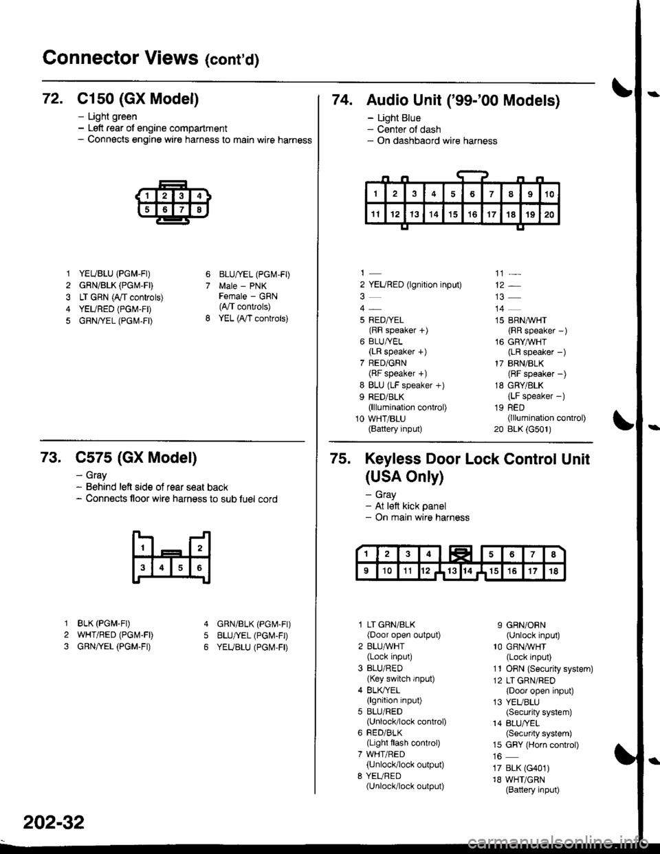
72. C1s0 (GX Model)
1 YEUBLU (PGM-FI)
2 GRN/BLK (PGM.FD
3 LT GRN (A/t controls)
4 YEURED (PGM-FD
5 GRN/rEL (PG|\,1-FD
- Light green- Left rear of engine compartment- Connects engine wire harness to main wire harness
6
7
BLU/IEL (PGM-FD
Male - PNKFemale - GRN(4,/T convols)
YEL (A,/T controls)
74. Audio Unit ('99-'00 Models)
- Light Blue- Center ol dash- On dashbaord wire harness
2 YEURED (lgnition input)
5 RED/YEL(RF speaker f)
6 BLU/YEL(LR speaker +)
7 RED/GRN(BF speaker +)
I BLU (LF speaker +)
9 RED/BLK(lllumination control)
10 WHT/BLU(Battery input)
']]]-
12*
14
15 BRN,^/VHT
{RR speaker -)
16 GRYAVHT(LR speaker -)
17 BRN/BLK(RF speaker -)
18 GRY/BLK
{LF speaker -)
19 RED(lllumination control)
20 BLK (G501)
73. C575 (GX Model)
BLK (PGM.FD
WHT/RED (PGI\4-FD
GRN/YEL (PGM.FI)
- Gray- Behind left side of rear seat back- Connects floor wire harness to sub luel cord
5
1
2
3
GRN/BLK (PGr\4-Fr)
BLU/YEL (PGI\'-FD
YEUBLU (PGI\,4,FD
202-32
75. Keyless Door Lock Control Unit
(USA Only)
- Gray- At lett kick panel- On main wire harness
l LT GRN/BLK(Door open output)
2 BLU,ryVHT(Lock input)
3 BLU/RED(Key switch input)
4 BLK/YEL(lgnition input)
5 BLU/RED(Unlock/lock control)
6 FED/BLK(Light flash control)
7 WHT/RED(Unlock/lock output)
8 YEURED(Unlock/lock output)
9 GRN/ORN(Unlock input)'10 GRNA/VHT(Lock input)
11 ORN {Securiiy system)
12 LT GRN/RED
{Door open input)
13 YEUBLU(Security system)
14 BLU/YEL(Security system)
15 GRY (Horn control)
17 BLK (G401)
18 WHT/GRN(Battery input)
Page 2140 of 2189
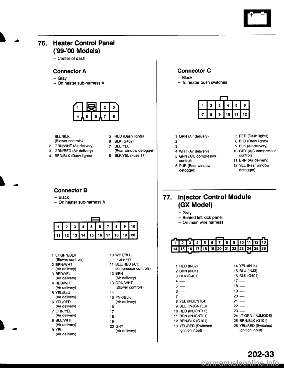
76. Heater Control Panel
('99100 Models)
- Center of dash
Conneclor A
- Gray- On heater sub-harness A
BLUi BLK(Blower controls)
GRNAVHT (Air delivery)
GRN/RED (Air delivery)
RED/BLK (Dash lights)
Connector B
- Black- On heater sub-harness A
7
8
1
4
RED (Dash lights)
BLK (G402)
BLUfYEL(Rear window defogg€0
BLK,TYEL (Fuse 17)
\
)
1 LT GRN/BLK(Blower controls)
2 BRN,A/VHT(Air delivery)
(Air delivery)
4 REDA/VHT(Air delivery)
5 YEUBLU(Air delivery)
6 YEURED(Air delivery)
7 GRN/YEL(Air delivery)
8 BLU,ryVHT(Air delivery)
9 YEL
{Air delivery)
1O WHT/BLU(Fuse 47)
11 BLU/RED WCcompressor controls)
12 BRN(Air delivery)
13 ORNAVHT(Blower controls)
14 -
15 PN(BLK(Air delivery)
16 _
19 _
20 GRY(Air delivery)
Connector C
- Black- To heater push switches
1 ORN (Air delivery)
2
4 WHT (Air delivery)
5 GRN (ry'C compressorcontrol)
6 PUR (Roar windowdelogge4
7 RED (Dash lights)
8 BLU (Dash lights)
I BLK (Air delivery)
10 GRY (Ay'C compressorcontrols)
1'1 BRN (Air delivery)
12 YEL (Rear window
defogge0
77. Injector control Module
(GX Model)
- Gray- Behind left kick panel- On main wire harness
1 RED (rNJ2)
2 BRN (rNJl )3 BLK (G401)
4_
8 YEL (TNJCNTL4)
9 BLU (TNJCNTL3)
1o RED (tNJCNTL2)
11 BRN 0NJCNTL1)12 BRN/BLK (G101)
13 YEURED (Switched
ignition input)
14 YEL (tNJ4)
15 BLU (rNJ3)
16 BLK (G401)
19 -
20-
21
24 LI GRN (INJMODE)
25 BRN/BLK (Gr 01)
26 YEURED (Switched
ignition input)
202-33
Page 2143 of 2189
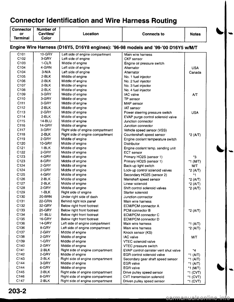
Connector ldentification and Wire Harness Routing
Connector
or
Terminal
Number ot
Cavities/
Golor
LocationConnects toNotes
Engine Wire Harness (Dl6Y5, D16Y8 engines): '96-98 models and '99;00 D16Y5 dM/T
c101
c102
c 103
c104
Q104
c105
c106
c107
cl 08
cl09
cl10
c1l1
cl'12
c113
c114
c'115
c116
c'117
c 118
c119
c120
c121
c122
c123
c123
c124
Q124
c125
c 126
c127
c128
c129
c130
c131
cl32
c 134
c135
c136
c137
c138
c139
c'140
c141
c142
c143
c144
c'|44
c145
c146
c147
1O-GRY
3.GRY
1-CLR
4-GRN
3-N/A
2-BLK
2-BLK
2-BLK
2-BLK
3-GRY
3-GRY
3-GRY
2.BLK
2.GRY
2-BLK
14-BLU
14-GRY
3.GRY
2-BLK
2-GRY
1O-GRY
1.BLK
2.GRY
4-GRY
8-GRY
2-GRY
2.GRY
4-GRY
2.BLK
2.BLK
2-GRY
1.BLK
2O.BRN
22.GRN
32.GRY
25.GRY
31-BLU
16.GRY
14-GRY
8.GRY
2-GFIY
2.GRY
1-GRY
2-GRY
2-BLK
2-GRY
2.BLK
3-GRY
6-GRY
2.BLK
8-GRY
2-BLK
Left side of engine compartment
Left side of engine
Middle of engineI att .i.la ^f an^i^6
Left side ot engine
Middle of engine
Middle of engine
Middle of engine
Middle of engine
Middle of engine
[,liddle of engine
Middle ot engine
Middle ot engine
Middle of engine
Middle of engine
Middle of engine
l\,liddle of engine
Right side of engine compartment
Right side of engine compartment
Middle ot engine
Middle of engine
Middle of engine
Middle of engine
l\,liddle of engine
Nliddle of engine
Middle ot engine
Middle of engine
Middle ot engine
Middle of engine
Middle of engine
Nliddle of engine
Right side of engine
Under right side of dash
Behind right kick panel
Below right front footrest
Below right front footrest
Below right front footrest
Below right front tootrest
Left side ot engine compartment
Left side of engine compartment
Middle of engine
liliddle ot engine
Middle of engine
Nriddle ol engine
Right side of engine compartment
Middle ol engine
Right side of engine compartment
Middle of engine
N,liddle of engine
Right side of engine compartment
Right side of engine compartment
Bight side of engine compartment
Main wire harness
CKF sensor
Engine oil pressure switch
Alternator
Alternator
No. 1 fuel injector
No. 2 fuel injector
No. 3 fuel injector
No.4 fuel injector
IAC valve
TP sensor
MAP sensor
IAT sensor
Power steering pressure switch
EVAP purge control sol€noid valve
Junction connector
Junction connector
Vehicle speed sensor (VSS)
Countershatt speed sensor
Engine coolant temperature switch
Distributor
Engine coolant temp. sending unit
ECT sensor
Primary HO2S (sensor '1)
Primary HO2S (sensor '1)
Back-up light switch
Lock-up control solenoid valves
Secondary HO2S (sensor 2)
lvlainshafl speed sensor
Lanear solenoid
Shift control solenoid valves
Starter solenoid
Junction connector
Main wire harness
ECM/PCM connector A
PCM connector B
ECM/PCNI connector C
ECM/PCl\,,| connector D
Main wire harness
Maln wire harness
Knock sensor (KS)
IAC valve
VTEC solenoid valve
VTEC pressure switch
EVAP control canister vent shut valv€
EGR control solenoid valve
Secondary gear shatt speed sensor
EGR valve
EGR valve
Drive pulley speed sensor
CVT transmission solenoid
Driven pulley speed sensor
USA
Canada
AlT
USA
'2( tr\
'3
-1 (M/r)
t\4/T'2 (Anl'1
'2 (An)'2 (Nr)'2 (AtT)
'2 (Atr)
-1 (An)-2( fi|
M/T
.1 (Arr).1 (A,T)"1 (A/r)-1 (M/r).1 (CVT),1 (cw)'1 (CVT)
203-2