1999 HONDA CIVIC main relay
[x] Cancel search: main relayPage 1212 of 2189
Le
\.t
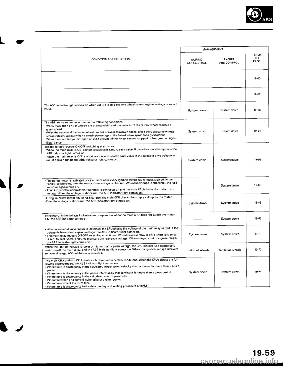
CONDITION FOR DETECTION
MANAGEI\,4ENT
FEFERTOPAGEDUNINGABS CONTFOLEXCEPTABS CONTAOL
19-60
19-62
The ABS indicator lighl cones on when vehicle is stopp€d and wheel sensor a given vohaqe does nol
19 64
The ABS indicaror comes on under th€lollowing conditions.When morethan one otwheels are a standstiland thelelocirv otthe fastest wheel reaches a
' fohen th. velocity of the faslesl wheel reaches or exceds a given sped, and it there ar€ somewh@lswhose velocity is slowe.lhan a cenain percenlage oi lh€ fast6t wheelsped for 3 given period. when rhere are lemporary open or short ctcuits ol rhe wheel sonsor' chipp€d pulser gear, orsrgnalorslJrbaaLe
19 64
The main relay repeats ON/OFF switching atalltimes.WhenthemainrelayisON,ashortt$tpulseissentloeachvalve lfthere s some dis'repa ncv, lheABS indicalor lightcomes on.. When rhe main relay is OFF, a shonl€sl pulse is s€nlto each valve lfth6 solenoid drive voltage rsout ol a qiven range, the ABS ndicalor lighl comes on19-66
'The pump nolot s activaled orc€ o' Mrce sfier every gn't'on sw'lch ON (ll) operarion whrle lte -^vchicle acLelerales lrenthemolorotivevo'taSersrhecled When lhevolla96 rs abnormar,lre Absindicaror llghl comes on.. Afte. ABS ;onl rol com pletion, the moror isswitched ofi 6nd the main CPU checks the molor dnvevoltase. when rhe vortase is abnormsl, the ABS indicato49!!!99!:l!:_-
19-68
D!rino an active motor lesl or AAS control,lhe main CPU checks ihe supplv voltage to the motor'whe;lhe vohage s abnofmal, the ABS indicator lightcomes on19,68
lirhe moror drvevoltage indicates molot operalion when the main cPU does notswilch the motoroN, rhe ABs indicaro. comes on19-64
. Wh"" " ".1"".1d ""1r. f"llure is detecred, the CPU checksth€ voltage ofthe main rel6v output lllhevohaqe is lowerthan 6 given vohage, theABS indicator light comes on. The ;ain r€lay repeats ON/OFF switching ar a!ltimss when the main rel.v is ofi, a shorl l6st pulse
is sent ro €ach valve. The CPU mon tors the reJer€nce vohage ll the vohage is out ot a g iven range'
the ABS indic.tor lightcomes on
19 71
wt'",, rt'e lgnitlon rottag" is ower or higherthan a given voltage,lhe CPU inhibils ABSlonlrolandswirches oli the ma in relaY, 6nd the ABS indicaror lig ht com€s on When the ig n ilion vohage recove'sto normal f6ng6, ABS inhibition is canceled.19.73
rimln CpU anO suU CeU ch€ck each other undercertain condnions. Whon rhe CPUS dstectthe fol'lowing discrepanaies, rhe ABS indicator light comss on. whe; rh€re is discGpancv n lhacarculated wheelspeed velocirv thar continuosJor more than a given
.i^/hen rhere is discrcoancv in the ehase informalion lhat continuesfor morerhan a given period' When rhere is discrepancY in thecalculared conlfol pa.amerer'. When thewatch dog conrrolp!lsetailslof a given penod. When th6 checkotth€ ROM tai1s.. when there is disrepancy inrhe data roading.nd wriung prcledurc ot RAM
19 7'l
tr
19-59
Page 1224 of 2189
tfMain Relay
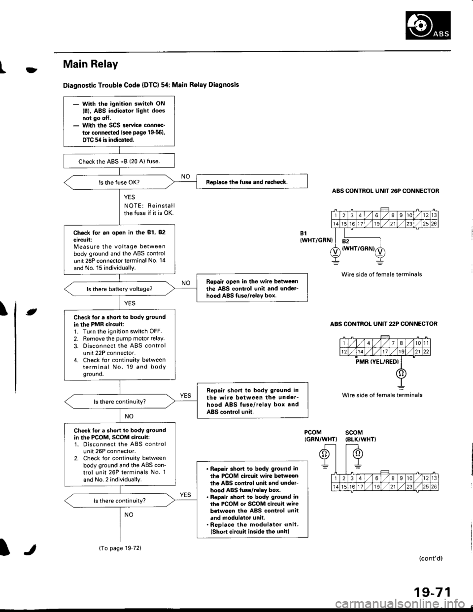
Diagnostic Trouble Code {DTC} 54: Msin Relay Diagnosis
YES
NOTE: Reinstallthe fuse if it is OK.
ABS CONTROL UNIT 26P CONNECTOR
Wire side of female terminals
ABS CONTROL UNIT 22P CONNECTOR
B1{WHT/GRNI
\e
PCOMIGRN/WHT}scoM{BLK/WHTI
(cont'd)
19-71
Wire side of female terminals
- With the ignition switch ON
{ll), ABS indic.tor light doesnot go off.- With the SCS 3ervica connoc-
tor connected (s€e pag€ 19-561,
DTC 54 is indicated.
checkthe ABS +B (20 Alfuse.
Replace th6 fuso and rechock.
Ch€ck for an op€n in the 81, 82
circuit:Measure the voltage betweenbody ground and the ABS control
unit 26P connector terminal No. '14
and No. 15 individually.
Repair open in the wire betweonthe ABS control unit and under-hood ABS tuse/relav box.
Check for a short lo body ground
in the PMR circuit:1- Turn the ignition switch OFF.
2. Remove the pump motor relay.
3. Disconnect the ABS controlunit 22P connector.4. Check for continuity betweenterminal No. 19 and bodygrouno.
Repair short to body ground in
the wire between the undor-hood ABS fuse/relay box andABS control unit.
ls there continuity?
Check tor a short to body ground
in the PCOM, SCOM circuit:1. Disconnect the ABS controlunit 26P connector.2. Check for continuity betweenbody ground and the ABS con-trol unit 26P terminals No. 1
and No.2 individually.
. Bepai. short to body ground in
tho PCOM circuit wire betwoenthe ABS control unit and under-hood ABS fu3e/.olay box.. Repair 3hort to body ground inthe PCOM or SCOM circuit wirebetween the ABS control unitand moduletor unit.. Rcplace th6 modulator unit.(Short circuit insido tho unit)
ls there continuity?
{To page 19 72)lr
Page 1225 of 2189
Troubleshooting
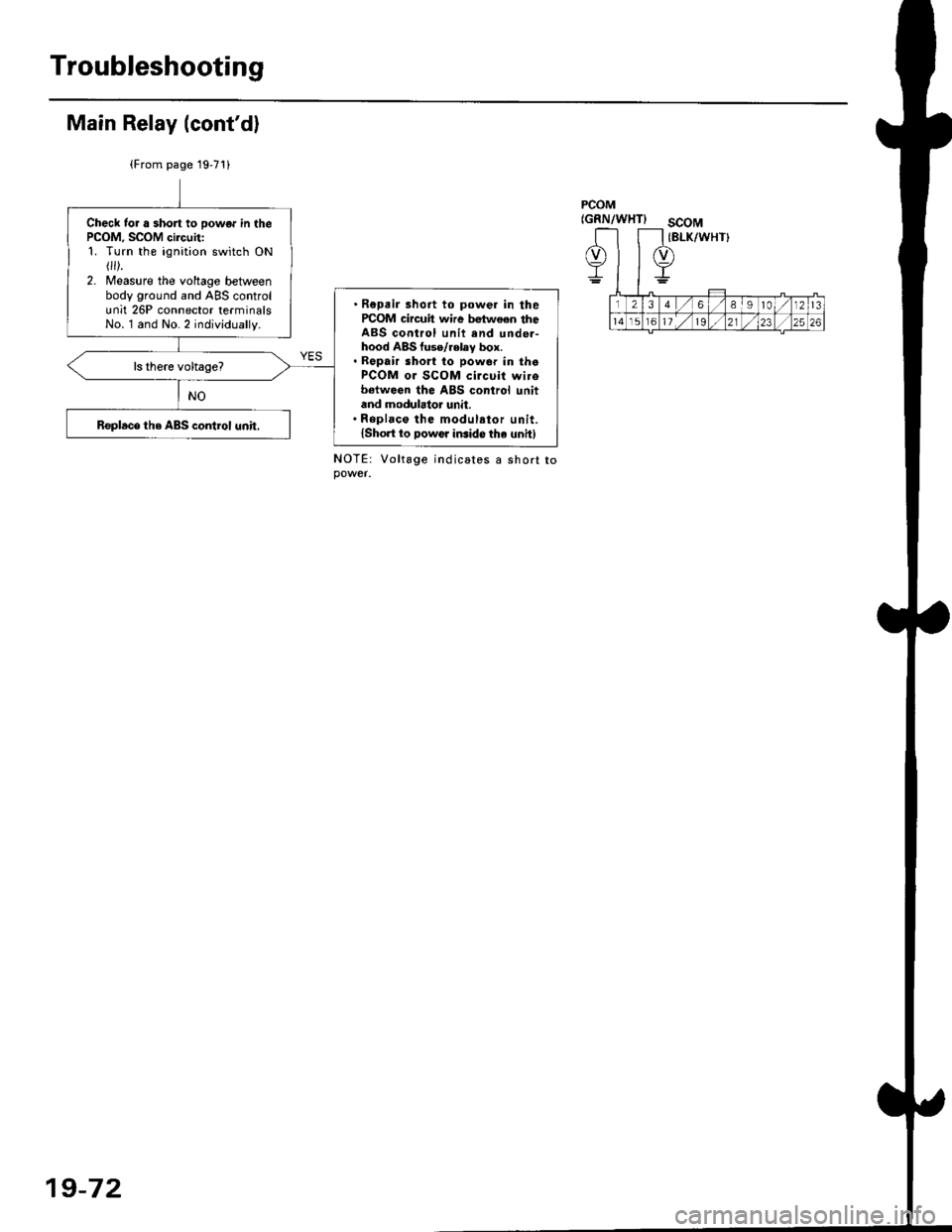
Main Relay (cont'd)
(From page 19'71)
PCOM(GRN/WHTIscoM(BLK/WHT}Check tor a short to powor in thePCOM, SCOM circuit:1. Turn the ignition switch ON r).2. Measure the voltage betweenbody ground and ABS controlunit 26P connector terminalsNo. l and No.2 individually.
. Repair 3hoit to power in ihercOM circuil wire bgtween theABS control unit end unde.-hood ABS fuse/relay box.. Repair sho to powor in thaPCOM oJ SCOM circuit wirobetwoen the ABS control unitand modulator unit.' Repl.co the modul.tor unit.lshort to Dowcr iGido the unit)Replace the ABS control unit.
Vo lta ge
19-72
Page 1300 of 2189
Dashboard
Gomponent Removal/lnstallation
(cont'd)
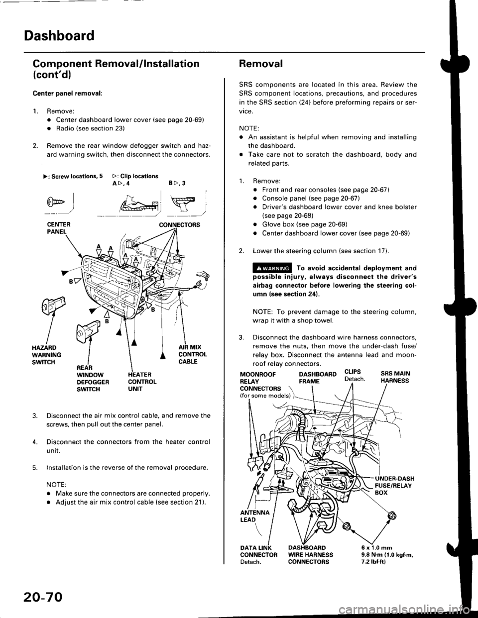
Center panel removal:
1. Remove:
. Center dashboard lower cover (see page 20-69)
. Radio {see section 23)
2. Remove the rear window defogger switch and haz-
ard warning switch, then disconnect the connectors.
>: Screw locations, 5 >: Clip locationsA>,4 B>,3
fii*-)
CENTERPANEI.
rt-xR.
W
IHAZARDWARNINGswlTcH
r44 "
F.IZvl
IIREARwtNoowOEFOGGERswtrcH
MtxCONTNOLCABLE
3. Disconnect the air mix control cable, and remove the
screws, then pull out the center panel.
4. Disconnect the connectors from the heater control
u nit.
5. Installation is the reverse of the removal procedure.
NOTE:
. Make sure the connectors are connected properly.
. Adjust the air mix control cable (see section 21).
20-70
Removal
SRS components are located in this area. Review the
SRS component locations, precautions, and procedures
in the SRS section (24) before preforming repairs or ser-
vice.
NOTE:
. An assistant is helpful when removing and installing
the dashboard.
. Take care not to scratch the dashboard, body and
related parts.
1. Remove:
o Front and rear consoles (see page 20-67)
. Console panel (see page 2O 67),
. Driver's dashboard lower cover and knee bolster(see page 20-68)
. Glove box (see page 20-69)
. Center dashboard lower cover (see page 20-69i
2. Lower the steering column (see section 17).
@ To avoid accidental deplovment and
possible injury, always disconnect the driver's
airbag connector belore lowering the steering col-
umn lsee section 241.
NOTE: To prevent damage to the steering column,
wrap it with a shop towel.
3. Disconnect the dashboard wire harness connectors,
remove the nuts, then move the under-dash fuse/
relay box. Disconnect the antenna lead and moon-
roof relay connectors.
DASHBOARD cltPs
CONNECTORS(for some models)
MOONROOFRELAY
ANTENNALEAO
FRAME
SRS MAINHARNESS
9.8 N.m (1.0 kgf m,7.2lbt.ltl
DATACONNECTOR WIRE HARNESSDetach. CONNECTORS
Page 1483 of 2189
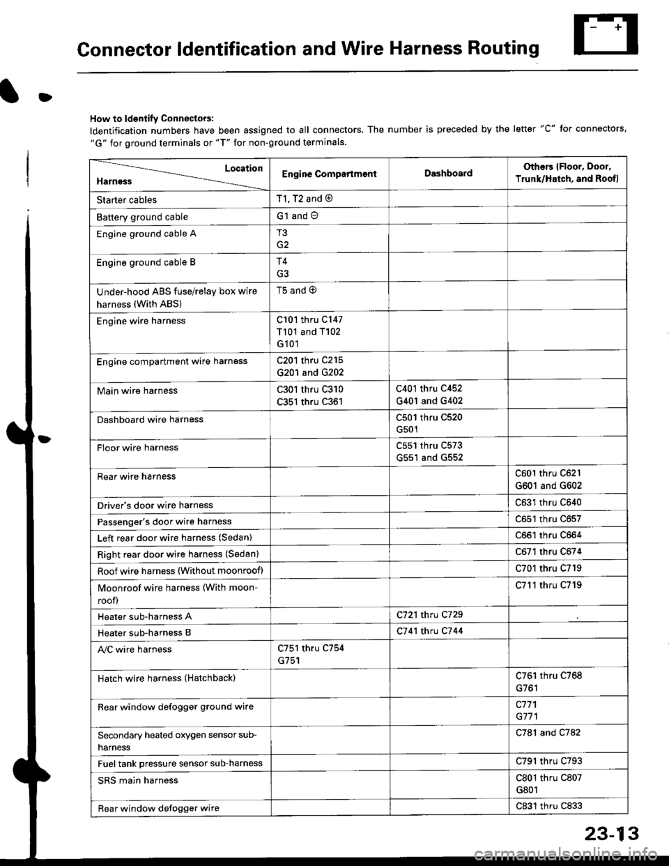
Connector ldentification and Wire Harness Routing
D
How to ldentify Connectors:
ldentification numbers have been assigned to all connectors. The number is preceded by the letter "C" for connectors,"G" for ground terminals or "T" for non-ground terminals.
Location
HarnessEngine CompartmentDashboardOthers {Floor, Door,
Trunk/Hatch, and Rootl
Starter cablesT1, T2 and @
Battery ground cableG1 and O
Engine ground cable AT3
G2
Engine ground cable BT4
Under-hood ABS fuse/relay box wire
harness (With ABS)
t5 ano (9
Engine wire harnessCl01 thru C147
T101 and T102
G101
Engine compartmenl ware harnessC201 thru C215
G201 and G202
Main wire harnessC301 thru C310
C351 thru C361
C401 thru C452
G401 and G402
Dashboard wire harnessC501 thru C520
G501
FIoor wire harnessC551 thru C573
G551 and G552
Rear wire harnessC601 thru C62l
G601 and G602
Driver's door wire harnessC631 thru C640
Passenger's door wire harnessC651 thru C657
Left rear door wire harness (Sedan)C661 thru C664
Right rear door wire harness (Sedan)C671 thru C674
Roof wire harness (Without moonroof)C701 thru C719
Moonroof wire harness {With moon-
roof)
C7l'l thru C719
Heater sub-harness AC721 thru C729
Heater sub-harness BC7 41 thtu C7 44
Ay'C wire harnessC751 thru C754
G751
Hatch wire harness (Hatchback)C761 thru C768
Rear window defogger grgund wirec771
G171
Secondary heated orygen sensor sub-
narness
C781 and C782
Fuel tank pressure sensor sub-harnessC791 thru C793
SRS main harnessC801 thru C807
G801
Rear window defogger wireC831 thru C833
Page 1486 of 2189

Connector ldentification and Wire Harness Routing
Engine Wire Harness lD16Y5, D16Y8 enginss): '96 - 98 models
Connector or
Torminal
Numbsr of
CavitissLocationConnects toNot€s
c 101c102c103c104c104c105c106c107c108c 109c110c111c112c113c114c115c116cl17c118c119c120cl21
c122c123cl23c124
c125
c127c12Ac129c130c131c132c 133c134c135
c136
c138c139c140c 141c142c 143c144cl44c145c'146cl47
10
1
22
14l4322l0I
2
2
2
2120
3l
14
14
1222
2
2
22
Left side of engine compartmentMiddle of engineMiddle of engineLeft side of engine companmentLeft side of engine compartmentMiddle of engineMiddle of engineMiddle of engineMiddle of engineMiddle of enginefvliddle of engineMiddle of engineMiddle of engineMiddle of engineMiddle of engineMiddle of engineMiddle of engineLeft side of engine compartmentMiddle of engineMiddle of engineMiddle of engineMiddle of engine
Middle of engineMiddle of engineMiddle of engineMiddle of engineMiddle of engineMiddle of engineMiddle of engineMiddle of engineMiddle of engineRight side of engine companmentBehind right kick panelUnder right side of dashUnder riOht side of dashUnder right side of dashUnder right side of dashUnder right side of dashUnder right side of dash
Under right side of dash
Under right side of dash
Middle of engineMiddle ot enginel iddle of engineMiddle of engineMiddle of ongineMiddle of engineLeft side of engine compartmentMiddle of engineMiddle of engineRight side of engine compartmentRight side of engine compartmentRight side of engine compartment
USACanada
Afi
USA
-' (A/r)
Main wire harness (C303)Crankshaft speed fluctuation (CKF) sensorEngine oil pressure switchAlternatorAlternatorNo. 'l fuel injectorNo. 2 fuel injectorNo.3 fuel injectorNo. 4 fuel injectorIAC valveThrottle position (TP) sensorl\4anifold absolute pressure (MAP) sensorIntake air temperature (lAT) sensorPower steering pressure {PSPI switchEVAP purge control solenoid valveJunction connectorJunction conn€ctorVehicle speed sensor {VSS}Countershaft speed sensorEngine coolant temp€rature (ECT) switch ADistributorEngine coolant temperature (ECT) sendingunrtEngine coolant temperature (ECT) sensorPrimary HO2S (sensor'l)Primary HO2S (sensor 1)Back-up light switchLock-up control solenoid valveSecondary HO2S (sensor 2)Mainshaft speed sensorLinear solgnoid valveShift control solsnoid valveStarter solenoidJunction connectorMain wire harnesE (C446)ECM/PCMPCMECMiPCMECM/PCMMain wire harness (C305)
Main wire harness (C305)
Main wire harness (C305)
Knock sensor (KS)IAC valveVTEC solenoid valveVTEC pressure switchEVAP control canister vent shut valveEGR control solenoid valveSecondary gear shaft speed sensorEGR valveEGR valveDrive pulley speed sensorSolenoid connector {CVT)Driven pulley speed sensor
*, (M/T)M/T*" INT\
*, tAtf)
NT:'96 model*,(A,/T):'97 - 98mooets
moqets
M/T
-1 (l,/T)*, (A,/T)-,(4,/T)*1 {M/T)*, (A,/T)*1 (CW)*, (A,T)
T101r102Left side of engine companmentRight side of engine companmentAlternatorUnder-hood fuse/relay boxG 101Middle of engineEngine ground, via engine wire harness
2
*1: Dl6Y5 engine*2: D16Y8 engine*3: D16Y5 (Ay'T), D16Y8 engines
3-16
Page 1488 of 2189
Gonnector ldentification and Wire Harness Routing
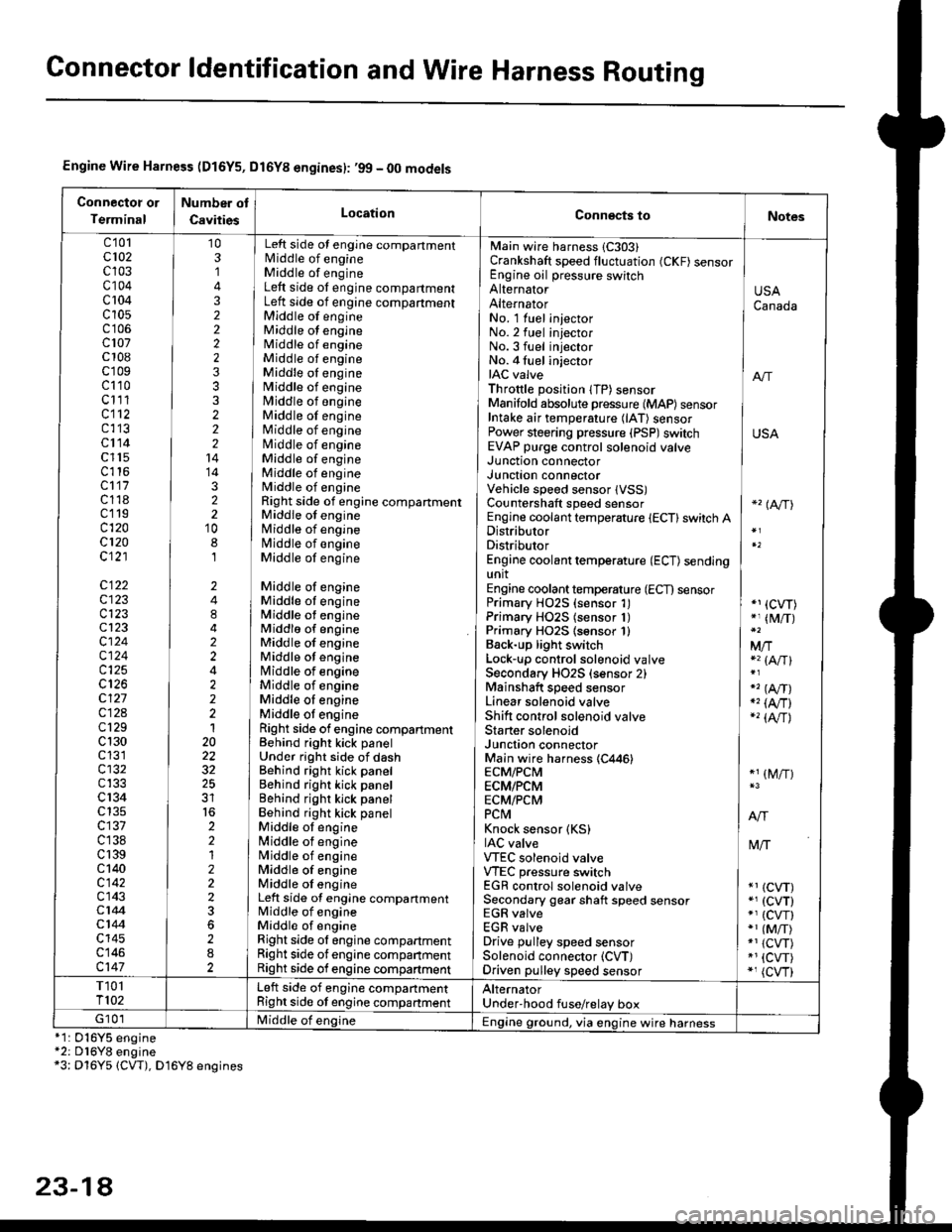
Engine Wire Harness (D16Y5, Dl6Yg engines): ,99 - 00 models
Connectot or
Terminal
Number ot
CavitiesLocationConn€cts toNotes
c'101cl02c103c104c 104c10s
c107c 108c'r09c110c111cl12c113cl14c l15c116cl17c118c119c120cl20c121
c122c123c123cl23cl24c124c125
c127c12Ac129c 130c131cl32c133c 134c135c137c138c 139c 140c142c143c144cl44c145c146c147
103,]
322223332221414322'10
8,l
2484224222120
32
2212223
282
No. 1 luel injector INo.2 fuel injectorNo.3 fuel injector ]No. 4 fuel injector iIAC valve I anThrottle position lTP) sensorManifold absolute pressure {MAP) sensor IIntake air temperature (lAT) sensor IPower steering pressure (PSP)switch USAEVAP purge control solenoid valve ]
Main wire harness 1C303)Crankshaft speed fluctuation (CKF) sensorEngine oil pressure switchAlternatorAlternator
Left side ot engine compartmentlvliddle of engineMiddle of engineLeft side ot engine compartmentLeft side of engine compartmentMiddle of engineMiddle ot engineMiddle of engineMiddle of engineMiddle oI engineMiddle of engineMiddle of engineMiddle of engineMiddle of engineNliddle of engineMiddle of engineMiddle of engineMiddle of engineRight side of engine compartmentMiddle of engineMiddle of engineN4iddle of engineMiddle of engine
Middle of engineMiddle ot engineMiddle ot engineMiddlo of engineMiddle of engineMiddle ot enginelrliddle of engineMiddle of engineMiddle oI engineMiddle ot engineRight side of engine compartmenlBehind right kick panelUnder right side of dashBehind right kick panelBehind right kick panelBehind righr kick panelBehind right kick panelMiddle ot engine[,liddle of engineN4iddle of engineMiddle of engineMiddle oI engineLeft side of engine compartmentMiddle of engineMiddle of engineRight side ol engine compartmentRight side of engine companmentRight side of engine compartment
USACanada
Junction connectorJUnct|On COnnectorVehicle speed sensor lVSS)Countershaft speed sensorEngine coolant temperature {ECT} switch ADistributorDistributorEngine coolant temperature (ECT) sendingunitEngine coolant temperature (ECT) sensorPrimary H02S (sensor 1)Primary HO2S (sensor 1)Primary HO2S lsensor 1)Back-up light switchLock'!p control solenoid valveSecondary HO2S (sensor 2)Mainshaft speed sensorLinear solenoid valveShift control solenoid valveStarter solenoidJunction connectorMain wire harness (C446)ECM/PCMECM/PCMECM/PCMPCtvtKnock sensor (KS)IAC valveVTEC solenoid valveVTEC pressure switchEGR control solenoid valveSecondary gear shaft speed sensorEGR valveEGR valveDrive pulley speed sensorSolenoid connector (CVT)Driven pulley speed sensor
*'� (A/TI
*1 (CVT)*, (M/T)
Mfia (A/Tl
" (A,/T)., (4,/r)-'� {AlrJ
*1 (M/T)
tvliT
*1 (CVT)*, (cvT)*' (cw)*1 (MiT)*1 {CVT)*1 {CVT)*, (cvr)
T101T102Left side of engine companmentRight side ot engine companmentAlternatorUnder'hood fuse/relay boxG 101Middle of englne IEngine ground, via engine wire harness*1: 016Y5*2: D16Y8*3: Dl6Y5
engineengine(CW), D16Y8 engines
23-14
Page 1490 of 2189
Gonnector ldentification and Wire Harness Routing
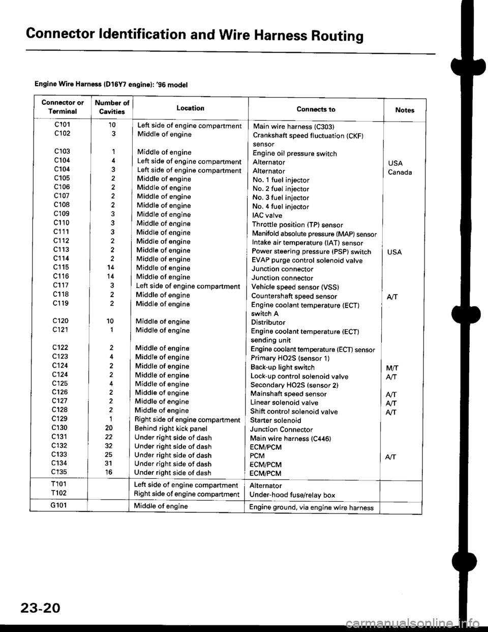
Engine Wire Harness {D16Y7 engine}: '96 model
Conneclor or
Terminal
Number ot
CavhiesLocationConnects toNotes
c101
c102
c 103
c104
c104
c105
c'r06
c107
c 108
c 109
c110
c111
c112
c l13
c't14
LttS
cl16
cl17
c118
cl19
c120
c121
c123
c124
c124
c125
c126
c't27
c12a
c129
c130
c131
c132
c133
c134
c135
10
1
4
5
'14
14
10
1
,,
2
2
1
22
31
16
No. 1 fuel injector INo. 2 fuel injector
No. 3 fuel injector INo,4 fuel injector
IAC valve l
Throttle position (TP)sensor IManifold absolute pressure (MAP) sensorIntake ai. temperature (lAT) sensor ]Power steering pressure (PSP) switch I USAEVAP purge control solenoid valve IJunction connector
Junction connector IVehicle speed sensor (VSS) |Countershaft speed sensor AlTEngine coolant temperature (ECT) I
Main wire harness (C303)
Crankshaft speed fluctuation (CKF)
sensor
Engine oil pressure switch
Alternator
Alternator
switch A
Distributor
Engine coolant temperature (ECT)
sending unit
Engine coolant temperature lECT) sensor
Primary H02S (sensor 1)
Back-up light switch
Lock-up control solenoid valve
Secondary HO2S (sensor 2)
Mainshaft speed sensor
Linear solenoid valve
Shift control solenoid valve
Staner solenoid
Junction Connector
Main wire harness {C446)ECM/PCM
PCM
ECM/PCM
ECM/PCM
Left side of engine compartment
Middle of engine
Middle of engine
Left side of engine compartment
Left side of engine compartment
Middle of engine
Middle of engine
Middle of engine
Middle of engine
Middle of engine
Middle of engine
Middle of engine
Middle of engine
Middle of engine
Middle of engine
Middle of engine
Middle of engine
Left side of engine compartment
Middle of engine
Middle of engine
Middle of engine
Middle of engine
Middle of engine
Middle of engine
Middle of engine
Middle of engine
Middle of engine
Middle of engine
Middle of engine
Middle of engine
Right side of engine compartment
Behind right kick panel
Under right side of dash
Under right side of dash
Under right side of dash
Under right side of dash
Under right side of dash
USA
Canada
M/T
AtJ
Afi
T101
T102
Left side of engine compartment
Right side of engine compartment
Alternator
Under-hood fuse/relay box
G101Middle of engineEngine ground, via engine wire harness
23-20