1999 HONDA CIVIC main relay
[x] Cancel search: main relayPage 508 of 2189

JI
I
- Repair open or 3hort in the
wire bstw€er the lGM-Fl mainrolsy .nd the No. 31 STARTERSGNAL 17.5 A) tuse.- Reolace the No. 31 STARTER
SIGNAL (7.5 Al fu3o in the
unde.-dash tusg/rolav box.
ls there baftery voltage?
Chock lor !n open in the wit.
lFLn line)l1. Turn the ignition switch OFF
2. Disconnect the ECM/PCM con-
nector A (32P).
3. Check for continuity between
the PGM-FI main relay 7P con-
nectorterminal No. 1 and ECM/
PCM connector terminal A16.
Ropair op6n in th. walo betwoanthe ECM/PCM lA16) and thc
PGM-FI main rolaY.
Ch6ck for an opon in th. wi.e3
llcPl,lGP2linesl:1. Reconnect the ECM/PCN4 con-nector A (32P).
2. Reconnoct the PGM-Fl main
relay connector,3. Turn the ignition switch ON (ll)
4. Measure voltage between
ECM/PCM connector termanals
A11 and A10, and betweenA24 6nd A10.
Repeir opon in th6 wire bet-
ween ttre ECiA /PCM (A11, A24)
and tho PGM-FI msin r.lty.
R€plac. tho FGM-FI main rc|.Y.
Check tor an open in the ECM/
PCM:1. Turn the ignition switch OFF.
2, Measure voltage between
ECM/PCM connector terminalsA16 and A10 when the ignition
switch is lirst turned ON (ll) for
two seconds.
Substituta a known-good ECM/
PCM and rechcck. lf proacribod
voltege is now availablc, r.Placethe originll ECM/PCM.
ls thero 1.0 V or less?
Ch6ck th. PGM-FI m.in lolay(.ee pagc 11-2371.
('96 - 98 models)
t32Pt
Wire side of female terminals
IGP2{YEL/BLKI
FLRIGRN/YELIPGl
3l5 6 7l lslel tl1l
1213'tal5t6't7t8t920221 232a
2527284t
(cont'd)
1 1-239
IBLK)
{GRN/YELI
FLR(GRN/YELI
23
()a6t
ECM/PCM CONNECTOR A
21Il0t1
12r31'al5't61'tti9ml,/x2232a
25212e293ol./
PGl (BLK)
1I
12't/t15t617t8t9zi
25272A4t304l
Page 509 of 2189
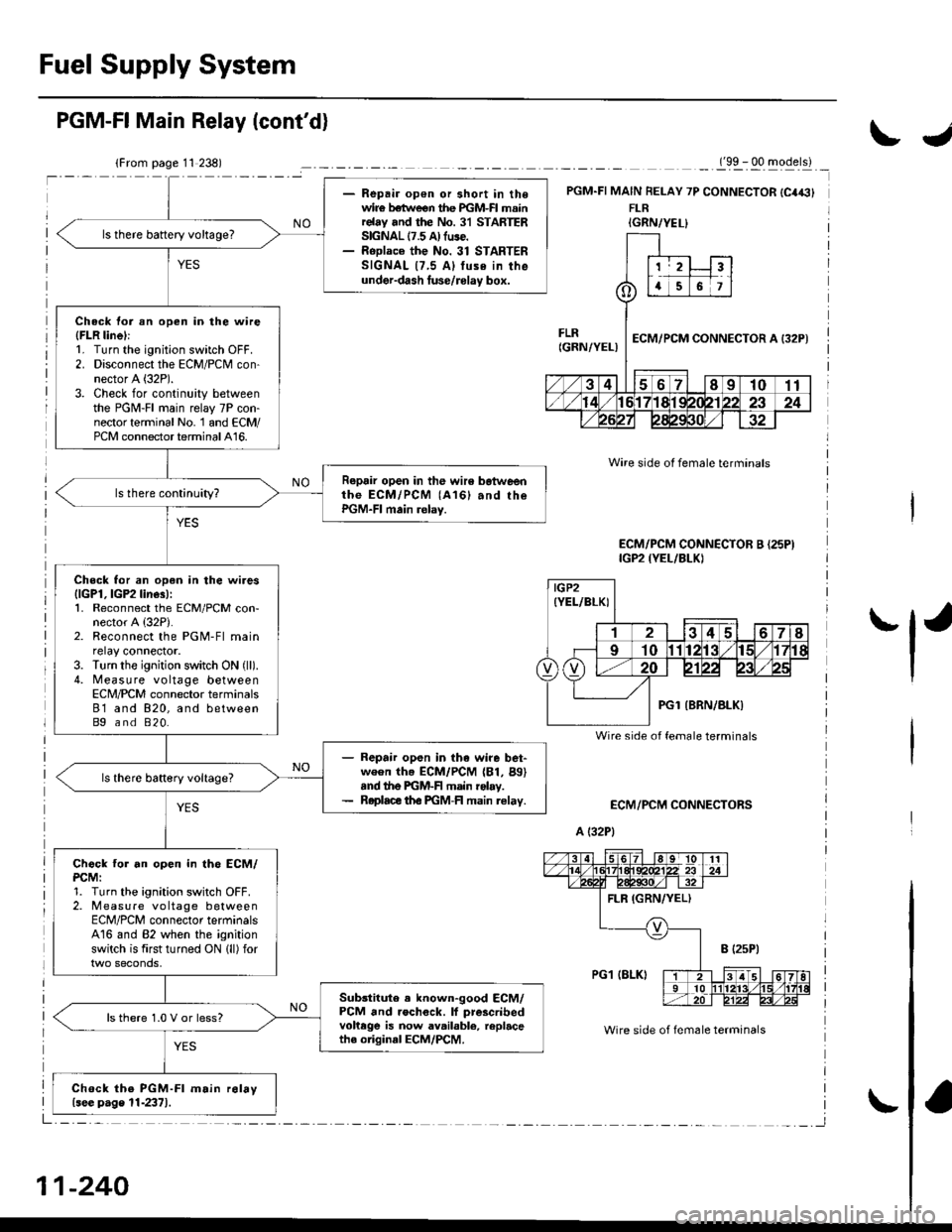
Fuel Supply System
- Repair op€n or short in thewir€ betlveen the PGM-FI mainrelay and the No. 31 STARTERSIGNAL 17.5 A) fuse.- RoDlace the No. 31 STARTERSIGNAL {7,5 Al tuse in theunder-dash luse/rolay box.
ls there battery voltage?
Check tor an open in the wire(FLR linel:1. Turn the ignition switch OFF.2. Disconnect the ECM/PCM con-nector A (32P).
3. Check for continuity betweenthe PGM-FI main relay 7P con-nector terminal No. 1 and ECM/PCM connector terminal A16.
Repair open in the wir6 botweenthe ECM/PCM (A161 and rhePGM-FI main relay.
Check for an open in the wires{lGPl, lGP2 line3):1. Reconnect the ECM/PCM con-nector A {32P).2. Reconnect the PGM-Fl mainrelay connector.3. Turn the ignition switch ON (ll).
4. Measure voltage betweenECN4/PCM connector terminals81 and 820, and betweenBg and 820.
- Repair open in the wire bet-ween th. ECM/PCM (81, Bg)snd the PGM-F main rolay.- Roplace th€ PGM-FI main relav.
Chock tor an open in th6 ECM/PCM:1. Turn the ignition switch OFF.2. Measure vo ltage betweenECM/PCM connector terminalsA16 and 82 when the ignitionswitch is first turned ON lll) for
Sub3titute . known-good ECM/PCM and rochock. lf prescribedvohege is now available, replacethe original ECM/PCM.
ls there 1.0 V or less?
Chock the PGM-Fl m.in r6lay{see p.ge 11-2371.
PGM-FI Main Relay (cont'd)
_._(9x . qq -gqerll _
PGM.FI MAIN FELAY 7P CONNECTOR {C4€}FLR
ECM/PCM CONNECTORS
A (32P1
Wire side ot female terminals
Wire side of fem6le terminals
ECM/PCM CONNECTOR B {25PIIGP2 {YEL/BLKI
IGRN/YEL}
IGP2(YEL/BLKI
Wire side of female terminals
11-240
IJ
'l'
Page 780 of 2189

Electrical Troubleshooting ('99 - 00 Models)
Troubleshooting Flowchart - E Indicator Light Does Not Come On
FCM CONNECTOR B (25P}
LGl {8RN/ALKI{BRN/8LK}
Wire side ol temale terminals
LGl IBNN/BLK} LG2 {BRN/BLK)
i2t5 6q
910t7
LG2
o) (o
The Pll indicator light does notcome on when the ignitionswitch is fi.st turned ON (ll). lltshould come on for about twoseconda.l
Check the Service Check Con-nector:Make sure the special tool (SCS
Service Connector) is not connect-ed to the service check connector?
ls the specialtool {SCS ServiceConnector) is not connected tothe seNice check connector.
Disconnect the special tool fromthe service check connector andr6check.
Check the Dll lndicator LightiShift to d position.
Check for loose terminal fit in thePCM connecto13. It necessary.sub3titute a known-good PCMand recheck.
Does the @ indicator lightcome on?
Check the Ground Circuit:1. Turn the ignition switch OFF.2. Disconnect the B (25P) con-nector from the PCM.3. Check for continuity betweenthe 820 terminal and bodyground, and between the 822terminal and body ground.
Repair open in the wiresbetween the B20 rnd 822 termi-nals and ground (G101), andrep.ir poor ground (G1011.
Measure Power Supply CircuitVoltage:1. Turn the ignition switch ON {ll}.2. Measure the voltage betweenterminals B1 and 822 andbetween terminals Bg and820.
Repair open or short in the wi.obetween th6 81 and/or 89 termi-nals and the PGM-FI main relav,and between th€ PGM-FI mainr€ley rnd the under-hood tus€/relay box.
To page 14''103
14-102
Page 909 of 2189
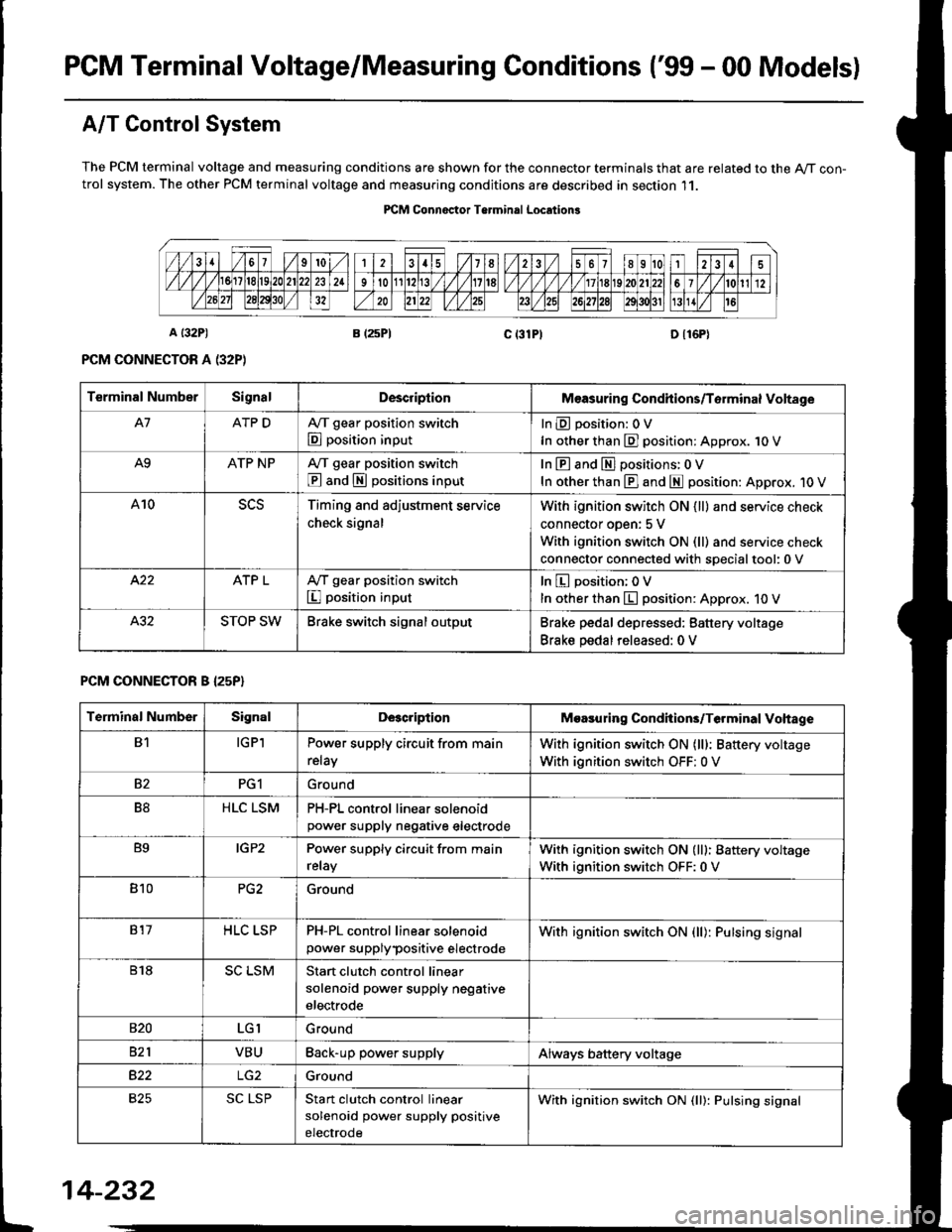
PGM Terminal Voltage/Measuring Conditions ('99 - 00 Modelsl
A/T Control System
The PCM terminal voltage and measuring conditions are shown for the connector terminals that are related to the A/T con-trol system. The other PCM terminal voltage and measuring conditions are described in section 11.
PICM Connoctor Terminrl Location3
Terminal NumberSignalDescriplionMeasuring Condhions/Torminal Voltage
A7ATP DA,/T gear position switch
E position input
InEposition:OV
In other than E] position: Approx. 1O V
A9ATP NPA/T gear position switch
@ and S positions input
In E and El positions: 0 V
In other than E] and E position: Approx. 1O V
A10Timing and adjustment service
check signal
With ignition switch ON {ll} and service check
connector oDen: 5 V
With ignition switch ON (ll) and service check
connector connected with soecialtool:0 v
ATP LA,/T gear position switch
I position input
In E position; OV
In other than E position: Approx. 10 V
STOP SWBrake switch signal outputBrake pedal depressed: Battery voltage
Brake pedal released: 0 V
PCM CONNECTOR B I25P}
Terminal NumberSignalDescriptionMoasuring Condhions/Terminal Vohage
B1IGPlPower supply circuit from main
relay
With ignition switch ON (lll: Battery voltage
With ignition switch OFF: 0 V
82PG1Ground
B8HLC LSMPH-PL control linear solenoidpower supply neqative electrode
B9IGP2Power supply circuit from main
relay
With ignition switch ON (lll: Battery voltage
With ignition switch OFF:0 V
810PG2Ground
817HLC LSPPH-PL control linear solenoid
power supplypositive electrode
With ignition switch ON {ll): Pulsing signal
818SC LSMStart clutch control linear
solenoid power supply negative
electrode
s20LGIGround
821VBUBack-up power supplyAlways battery voltage
B22Ground
825SC LSPStan clutch control linear
solenoid power supply positive
electrode
With ignition switch ON (ll): Pulsing signal
t
14-232
Page 965 of 2189
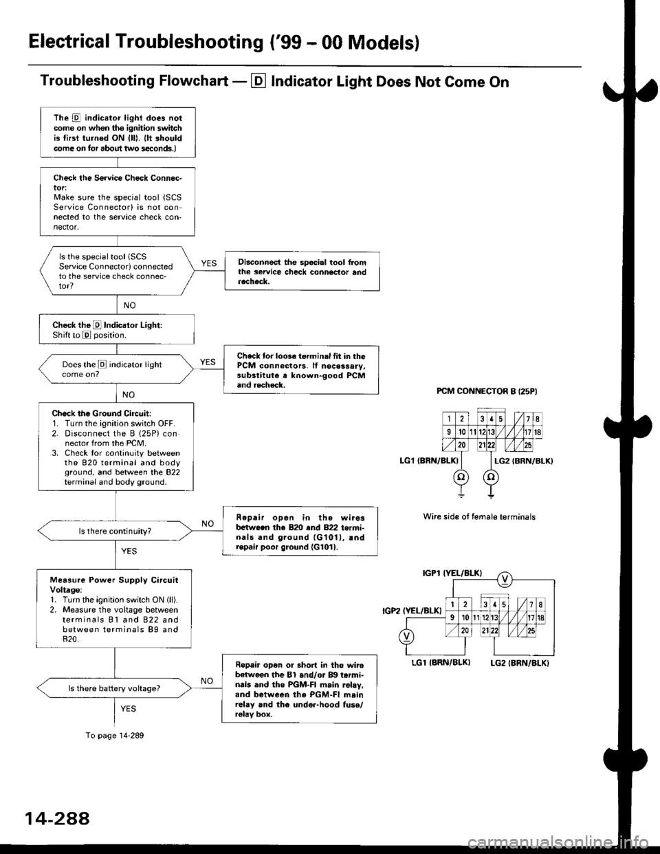
Electrical Troubleshooting ('99 - 00 Models)
Troubleshooting Flowchart - El Indicator Light Does Not Come On
PCM CONNECTOR B I25PI
LGl {BRN/BLK)
Wire side ot female terminals
LGlIARN/BLK) LG2IBRN/BLKI
The D indicator light does notcome on whon ths ignhion switchis tirst turned ON {lll. llt shouldcome on tor about two s€conds.)
Check the Service Check Connec-tor:Make sure the special tool {SCSService Connectorl is not connected to the service check con-nector,
ls the special tool (SCS
Service Connectorl connectedto the service check connec-tor?
Disconnect the sp€cial tool f]omthe seruice chcck connoclor andaecheck.
Check the E Indicalor Light:Shift to E posjtion.
Check tor loose te.minal fit in thePCM connectors, lf nocessary,substitute a known-good PCMand aecheck.
Does the E indicator light
Check the Ground Circuit:1. Turn the ignition switch OFF.2. Disconnect the B (25P) connector from the PCM.3. Check tor continuity betweenthe 820 terminal and bodyground, and between the 822terminal and body ground.
Fepair open in th. wirosb€tw.en the 820 end 822 termi-nals and ground {G1011, !ndrepair poor ground {G1011.
ls there continuity?
Measure Power Supply CircuitVoltage:1. Turn the ignitlon switch ON (ll).
2. Measure the voltage betweenterminals Bl and 822 andbetween terminals B9 and820.
Ropair op€n or short in tho wireb€tween the Bl and/or B!| tarmi-nds and the PGM-FI main .ohy,and between tho PGM-FI mainrelay and the under-hood fuso/r€lav box.
ls there battery voltage?
To page 14-289
14-2AA
Page 1196 of 2189
L-
t
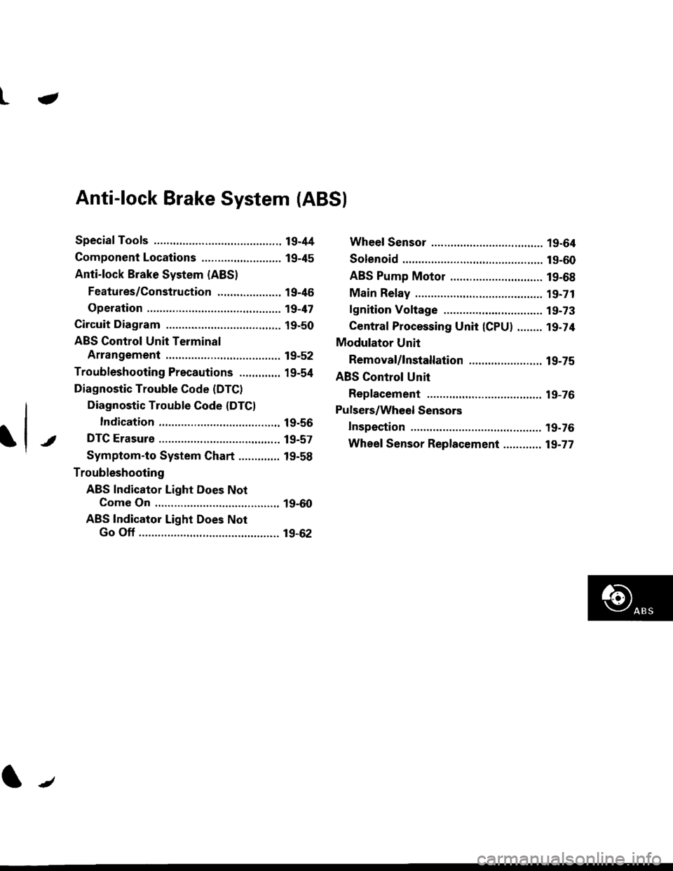
Anti-lock Brake System (ABSI
Special Tools ............. 19-44
Component Locations ......................... 19-45
Anti-lock Brake System (ABS)
Features/Construction ..................., 19-46
Operation ............... 19-47
Circuit Diagram ......... 19-50
ABS Control Unit Terminal
Arrangement ......... 19-52
Troubleshooting Precautions ............. 19-54
Diagnostic Trouble Code (DTCI
Diagnostic Trouble Gode (DTCI
Indication ........... 19-56
DTC Erasure ........... 19-57
Symptom-to System Chart ............. 19-58
Troubleshooting
ABS Indicator Light Does Not
Come On ............ 19-60
ABS Indicator Light Does Not
Go Off ............................................ 19-62
Wheel Sensor ........ 19-64
Solenoid ................. 19-60
ABS Pump Motor ............................. 19-68
Main Relay ............. 19-71
lgnition Voltage .... 19-73
Central Processing Unit {CPU} ........ 19-74
Modulator Unit
Removal/lnstallation ....................... 19-75
ABS Control Unit
Replacement ......... 19-76
Pulsers/Wheel Sensors
Inspection .............. 19-76
Wheel Sensor Replacement ............ 19-77
t/
Page 1200 of 2189
t-Operation
t
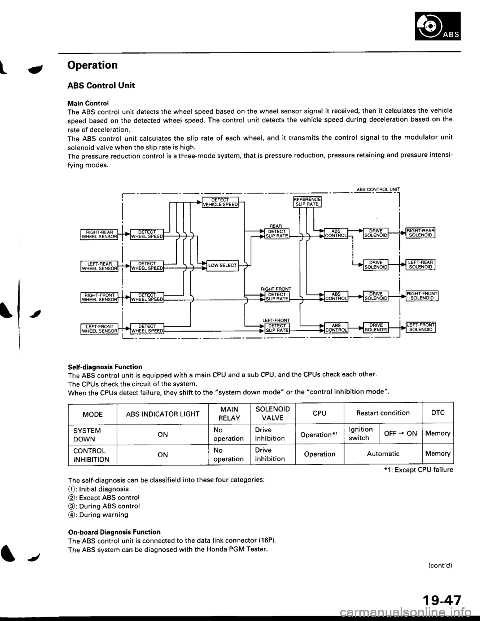
ABS Control Unit
Main Control
The ABS control unit detects the wheel speed based on the wheel sensor signal it received, then it calculates the vehicle
speed based on the detected wheel speed. The control unit detects the vehicle speed during deceleration based on the
rate of deceleration.
The ABS control unit calculates the slip rate of each wheel. and it transmits the control signal to the modulator unit
solenoid valve when the slip rate is high.
The pressure reduction control is a three-mode system, that is pressure reduction, pressure retaining and pressure intensi-
fying modes.
Self -diagnosis Funqtion
The ABS control unit is equipped with a main CPU and a sub CPU, and the CPUS check each other'
The CPUs check the circuit of the svstem.
When the CPUS detect failure, they shift to the "system down mode" or the "control inhibition mode"
The self-diagnosis can be classifield into these four categories:
O: Initial diagnosis
@: Except ABS control
@: During ABS control
@: During warning
On-board Diagnosis Funstion
The ABS control unit is connected to the data link connector {16P).
The ABS system can be diagnosed with the Honda PGM Tester.
(cont'd)
MODEABS INDICATOR LIGHTMAIN
RELAY
SOLENOID
VALVECPURestart conditionDTC
SYSTE IV
DOWNONNo
operation
Drive
inhibitionOperation*rlgnition
switchOFF + ONMemory
CONTROL
INHIBITIONONNo
operalron
Drive
inhibitionOperationAutomaticMemory
*1: Except CPU failure
/
19-47
Page 1207 of 2189
Troubleshooting Precautions
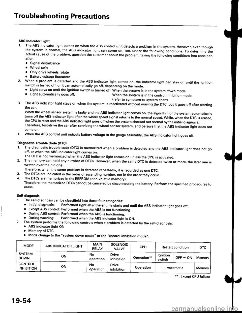
ABS Indicator Light
I The ABS indicator light comes on when the ABS control unit detects a problem in the system. However, even thoughthe system is normal, the ABs indicator light can come on, too, under the following conditions. To determine theactual cause of the problem, question the customer about the problem, taking the following conditions into consider-ation.
. Signal disturbance
. Wheel soin
. Only drive wheels rotate. Battery voltage fluctuates
2. When a problem is detected and the ABS indicator light comes on, the indicator light can stay on untat the ignitionswitch is turned off, or it can automatically go off, depending on the mode.. Lightstayson until the ignition switch isturned off;When the system is inthesvstem down mode.o Light automatically goes off:When the system is in the control inhibition mode.(refer to symptom-to-system chart)3 The ABS indicator light stays on when the system is reactivated without erasing the DTC, but it goes off after startingthe car.
when the wheel sensor system is faulty and the ABS indicator light comes on, the algorithm of the system automaticallyturns off the ABS indicator light after the wheel speed signal returns to the normal speed. while, when the DTC is erased,the CPU is reset and the ABS indicator light goes off when the system check€d out normal by the initial diagnosis.Therefore, test-drive the car after servicing the wheel sensor system, and be sure that the ABS indicator light does notcome on.
4. When the ABS control unit outputs battery voltage to the gauge assembty, the ABS indicator light goes off.
Diagnostic Trouble Code (DTC)
1. The diagnostic trouble code (DTC) is memorized when a problem is detected and the ABS indicator light does not gooff, or when the ABS indicator light comes on.The DTC is not memorized when the ABs indicator right comes on unress the cpU is activated.2. The memory can hold any number of DTCs. However, when the same DTc is detected twice or more, the later one iswritten over the old one.
Therefore. when the same problem is detected repeatedly, it is recorded as one DTC.3. The DTCS are indicated in the order of ascending number, not in the order thev occur.4. The DTCS are memorized in the EEpROM {non-volatile memorv}.Therefore, the memorized DTCS cannot be canceled by disconnecting the battery. perform the specified orocedures toerase.
Solf-diagnosis
1. The self-diagnosis can be classifield into these four categories:' Initial diagnosis; Performed right after the engine sta rts and untiltheABs indicator light goes off.o Except ABS control: Performed when the ABS is not functioning,. During ABS control: Performed when the ABS is functioning.. During warning: Performed when the ABS indicator light is ON.2 The system performs the following controls when a problem is detected by the self-diagnosis:. ABS indicator light ON. Memory of DTC
. Mode change to the "system down mode,, or the "control inhibition mode,,.
MODEABS INDICATOR LIGHTMAIN
RELAY
SOLENOID
VALVECPURestart conditionDTC
SYSTEM
DOWNONNo
operal|on
Drive
inhibitionOperation+rlgnition
switchOFF - ONMemory
CONTROL
INHIBITIONONNo
operat|on
Orive
inhibitionOperationAutomaticMemory
*1: Except CPU failure
19-54