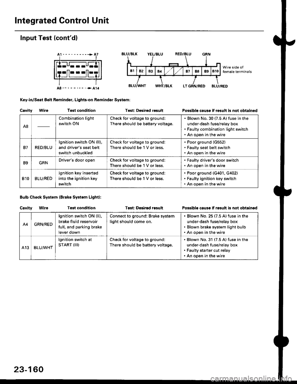
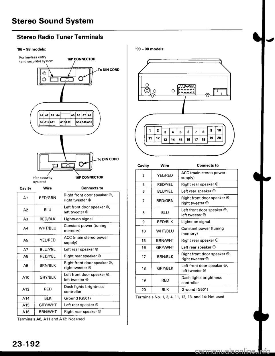
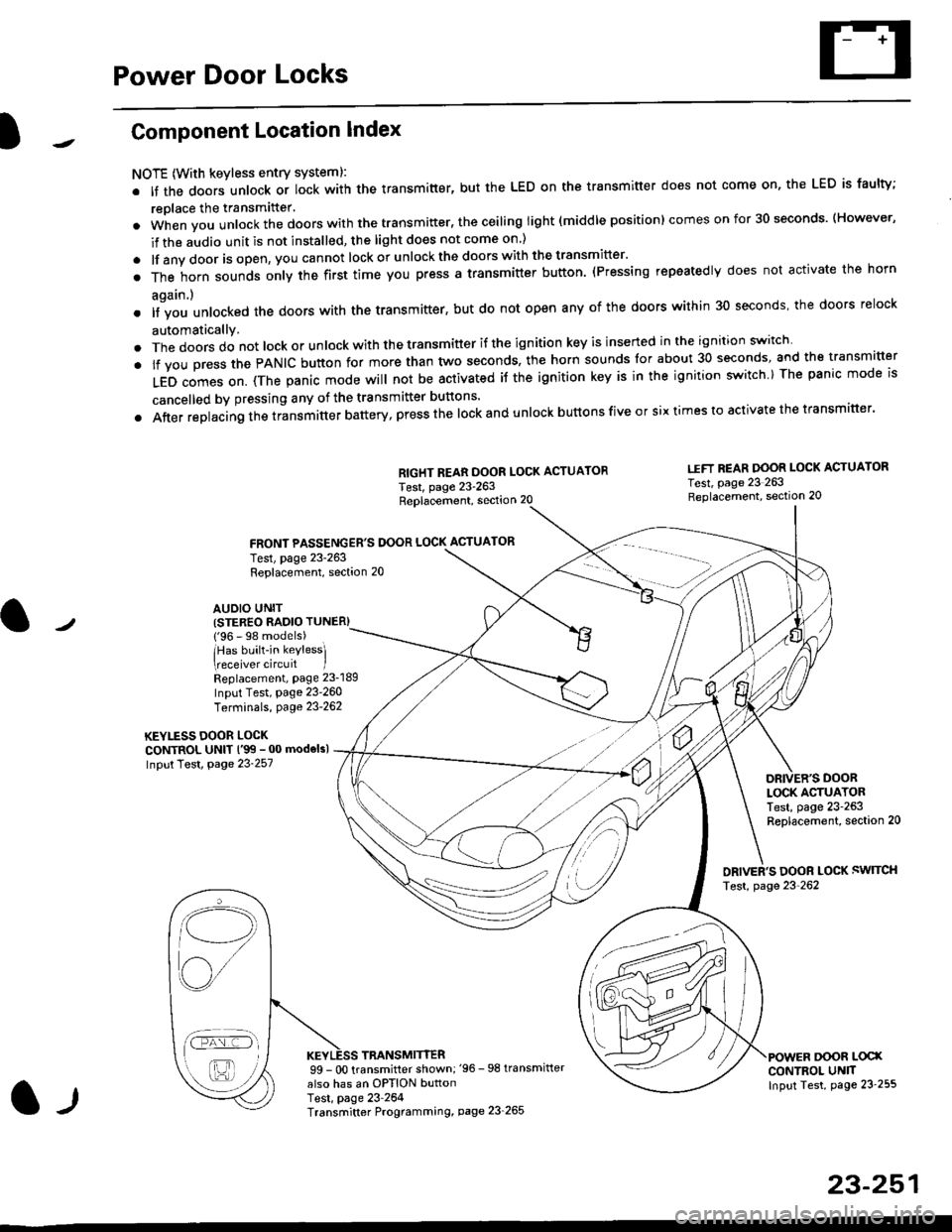
Page 1627 of 2189
(A,4)
A,T GEARPosrfloN swlrcH _ _(Closed h posilon l?l ot [!l )
BLU/BLK -> [h'#f- |COMEINATIONLIGHT SWITCH
V
IREO/GRN
UNDEF.DASH FUSEi RELAY BOX
a
E
YEL
I
A iEi,I,B"'T
vll".i,l
| ,rr.nrorro .orrro, ,*,,
tt-
t(
rffi
|
BEMI\DEB crqcurl
lm
| /t I
tffinEoTsru REDTBLU BLIJ/RED clnculr
-neoieru | ,,-,r.0 J
l, "ulTo
/fP /Itr\
YVI onrveqs I or rtor
l3fifl&''' l5frl'.'
l (3'&T' 8iytr") l
(3&Y fiti'fJ"fl )
BLK BLK
TT
c552 G401
I
. BRAKE FLUIDLEVEL SWITCH. PARKING ERAKEswrTcH (usA)
' CEILING LIGHT. KEYLESS RECE VER CIRCUIT(ln lhe audio unil")
..aorr,rro Y
A
Iu$ut,""'
I3fif'�3#3trr,)-::
DRIVER'SDOOFswtTcHfolosed : Door open )(Open :Doordosed/
STARTERCUT FELAY
a
-
GFNi RED
23-157
Page 1630 of 2189

Integrated Gontrol Unit
Input Test (cont'dl
A8--------.--all
Key-in/Seat Belt R€mind€r, Lights-on Reminder Systom:
Cavity WireTest condhion
Bulb Check System (Brako System Light):
Cavity WireTest condilion
Tost: D€sirod r€guh
T6st: Dosirad result
Possible cause if result is not obtained
Possibls cause if rasuft b not obtainod
A8
Combination light
switch ON
Check for voltage to ground;
There should be battery voltage.
Blown No.30 (7.5 A)fuse in the
under-dash fuse/relay box
Faulty combination light switch
An open in the wire
B7RED/BLU
lgnition switch ON (ll),
and driver's seat belt
switch unbuckled
Check for voltage to ground:
There should be 1 V or less.
Poor ground (G552)
Faulty seat belt switch
An open in the wire
B9GRNDriver's door openCheck for voltage to ground:
There should be 1 V or less.
. Faulty driver's door switch. An open in the wire
Bl0BLU/RED
lgnition key inserted
into the ignition key
switch
Check for voltage to ground:
There should be 1 V or less.
Poor ground (G401. G402)
Faulty ignition key switch
An open in the wire
A4GRN/RED
lgnition switch ON {ll),
brake fluid reservoir
full, and parking brake
tever oown
Connect to ground: Brake system
light should come on.
Blown No.25 (7.5 Alfuse in the
under-dash fuse/relay box
Blown brake system light bulb
An open in the wire
A13BLUA/1r'HT
lgnition switch at
START (III)Check for voltage to ground:
There should be battery voltage.
Blown No.31 (7.5 A) fuse in the
under-dash fuse/relay box
Faulty starter cut relay
An open in the wire
23-160
Page 1654 of 2189
Interior Lights
Circuit Diagram (With Spotlights)
SPOT.LGHTS
2
LT GRNlRED
t_:kr
(Wilh key ess enlry syslem)
t-t
-
, LTGRN/BLKKEYLESS RECEIVERCIBCUIT(ln the aLid o unil)
A
Y""I REARI DooF
t;:x::
| | 333i"
GBN L
A
Ttp;:'
Itsl";g;" I
I3331."..,J:
FFONTPASSENGERSDOORSWITCH
ictoseo : 'l
I Door openI Open :L Door closed _J
x I 3.4W :tiSA, Canada produced5W Japan produced*2 8w W lh moofroot5W Wlho!lmoonroof
23-144
UNDEB HOOD FUSEi RELAY BOX
LTGRN/RED
WHT/REDWHT/RED
r*r
I T 1,,'-1
'F!
I
I8LU/8LK
I
I
| *ttt-
| ,Y.
IBLUlBLK
A
Yiri'n
It3f.r'+m:r:r,lBLK
{
G601 G761 rHalchbac(G601 Coupe/Sedan
LTGRN/RED
Page 1662 of 2189

Stereo Sound System
Stereo Radio Tuner Terminals
'96 - 98 models:
For keyless entry . t6p coNNEcroR(and securrty) syslem
To DIN CORD
To DIN CORD
(for securitysystem)
Cavity Wire
A1RED/GRNRight front door speaker o,
right tweeter @
BLULeft front door speaker @,
left tweeter @
A3RE D/B LKLights-on signal
A4WHT/BLUConstant power (tuning
memoryl
A5YEL/REDACC (main stereo power
suppry)
A7BLUI/ELLeft rear speaker O
A8RE DI/E LRight rear speaker O
A9BRN/BLKRight front door speaker O,
right tweeter o
A10GRY/BLKLeft tront door speaker O,
left tweeter O
412REDDash lights brightness
controller
A14BLKGround (G501)
415GRYMHTLeft rear speaker O
Al6BR N/VVHTRight rear speaker O
Terminals A6, A11 and A13: Not used
23-192
'99 - 00 models:
CsvityConnccts toWire
2YEL/REDACC (main stereo power
suppry)
5RE DI/E LRight rear speaker @
BLUI/ELLeft rear speaker @
7RED/GRNRight front door speaker @,
right tweeter @
8BLULeft front door speaker @,
left tweeter @
9RED/BLKLights-on signal
10WHT/BLUConstant power (tuning
memory)
15BRN,ryVHTRight rear speaker O
GRYMHTLeft rear speaker O
17BRN/BLKRight front door speaker O,
right tweeter O
18G RY/BLKLeft front door speaker O,
left tweeter O
'19REDDash lights brightness
controller
20BLKurouno t(l5u t,
Terminals No. 1, 3, 4, 11,12, 13, and 14: Not used
Page 1721 of 2189

Power Door Locks
Component Location Index
NOTE (With keyless entry systeml:
. It the doors unlock or lock with the transmitter, but the LED on the transmitter does not come on, the LED is faulty;
replace the transmitter'
. when vou unlock the doors with the transmitter, the ceiling light (middle position) comes on for 30 seconds. (However,
if the audio unit is not installed, the light does not come on )
. lf any door is open, you cannot lock or unlockthe doors with the transmitter'
. The horn sounds only the first time you press a transmitter button. (Pressing repeatedly does not activate the horn
again.)
o lf vou unlocked the doors with the transmitter, but do not open any of the doors within 30 seconds, the doors relock
automatically.
. The doors do not lock or unlock with the transmitter if the ignition key is inserted in the ignition switch
. lf you press the PANIC button for more than two seconds, the horn sounds for about 30 seconds, and the transm'fer
LED comes on. (The panic mode will not be activated iJ the ignition key is in the ignition switch ) The panic mode is
cancelled by pressing any of the transmitter buttons'
o After replacing the transmitter battery, press the lock and unlock buttons five or six times to activate the transmitter'
Replacement, section 20
FRONT PASSENGER'S DOOR LOCK ACTUATOR
RIGHT REAR DOOR LOCK ACTUATOR
Test, page 23-263
I.IFT REAR DOOR LOCK ACTUATOR
Test, page 23 263Replacement, section 20
LOCK ACTUATORTest, page 23-263Replacement, section 20
ORIVER'S DOOR LOCK SWITCH
Test, page 23'262
DOOR L@XCONTROL UN]TInput Test, page 23 255
23-251
Test, page 23-263Replacement, section 20
AUDIO UNIT(STER€O RADIO TUNER)
{'96 - 98 models)
lHas built-in keylessl
eceiver circuit IReplacement, page 23-189
Input Test, page 23-260
Terminals, page 23-262
KEYLESS DOOR LOCKCONTROL UNIT l'99 - 00 modelsl
Input Test, Page 23-257
l-l
TRANSMITTER99 - 0O transmitter shown;'96 -98 transmifter
also has an OPTION buttonTest, page 23-264Transmitter Programming, page 23_265
Qi,,a/
/----
L(ru
i'.-8,-'l
/'-'6
Page 1722 of 2189
Power Door Locks
Circuit Diagram (With Keyless Entry System: '96 - 98 modelsl
WHTi BLK
WHT/BED
WHT/BLU
LOCK KNOB
n
Y KEY| -----.f--;-)
i-q__!J
8LK
G551
ll,o"., L
I PASSENGER'SI DoOF LOCKI ACTUATOR
IIYEUREO
WHT/RED WHT/FED
l,l,
tA-r rA] r.
qJ_*:[:,,,:
liqi*"""r llqi*'€trYELIRED YELi REDBLK
I
No.4l 180A) N0.42 (40A)
WHT/GRN
UNDER.HOOD FUSEi RELAY BOX
POWER OOOR LOCK CONTROL UN T
uNLocK@ rocK @
t'8LU/REDI'YELTRED
GRNiORN
GRN/]/VHT
BLK
G55l
23-252
Page 1723 of 2189
)1
ITRUNKLIGHT
GRNiRED LT GRN/ NED
AA
Ii,llh* T#,
I lctoseo : Door open ) | (ctoseo . ooo, open
I Looen Doot dosed J I Loner :ooot closet
tl
ll-: -l
@
wl
r,*1.,. ,,Tr,
,
I llltii irl:rx l5|i;e''lv
|
'r-1--
I
IBLU/YEL
TGFIVRED
I *r.oro,ro
I coNTRor uNrr
fF7IY \IT \
|L
GRN
AA
Y6su-' YFHrLo,,"
liili.}
',"**, r
liHi:
e*,**, r
ll-;
KEYLESS RECEIVER CIRCUIT(ln lhe audio unrl)
l"'l"l''o'*i*"
| |-"'i:"j^,"
l'*tectotroI coNTROL UNIT
I ,Y,
IBLU/RED
A
Y.r'ro,u
l:!llT -, ..".-
I
l-ope1 (ey temoved
BLK
I
);
G402
23-253
Page 1724 of 2189
Power Door Locks
Circuit Diagram (With Keyless Entry System : '99-00 models)
BL(
I
G551
UNDEF.HOOO FUSE/RELAY BOX
N0.41 1804) N0.51 (20 )
KEYLESSDOOF LOCKCOIJTROL UNIT
DRIVEF'SDOOF LOCKSWITCH
23-254