1999 HONDA CIVIC harness
[x] Cancel search: harnessPage 622 of 2189

Transmission
Reassembly (cont'd)
23, Tighten the transmission housing aftaching bolts in
the numbered sequence in several steps shown
Delow.
8 x 1.25 mm
Tolque: 27 N.m 12.8 kgf.m. 20 lbf.ft)
EACK.UP LIGHT SWITCHHARNESS BRACKET
24. Install the steel balls, springs, and set screws.
K)w
s
WASHERReplace.
STEEL EALLSD. 5i 16 in
SETTING SCREW22 N.m 12.2 kgf.m, 16 lbf.ftl
//-',, o/I .--"-4
;'c'-9,/t-)
13-42
L. 31.6 mm 11.24 in)
25. Install the back-up light switch and transmission
hanger.
8 x 1.25 mm27 N.m 12.8 kgl.m, 20 lbt.lrl
TRANSMISSIONHANGER
I./25 N.m (2.5 kgt.m, 18 lbf.ft)
Page 628 of 2189

Transmission Assembly
l
,
{
Removal
@Make sure iacks and safoty stands are placad plop-
erly (3ee section l).
Apply parking braks and block rear wheels so car
will not roll off stands and fall on you while working
under il.
CAUTION: Us6 fonder cove6 to avoid damaging painted
sudaces.
Disconnect the negative (-) cable from the battery,
then the positive (+l cable.
Drain the transmission oil. then reinstall the drain
plug with a new washer (see page 13-47).
Remove the intake air duct and the air cleaner hous-
ing assembly (see s€ction 5).
Disconnect the back-up light switch connector and
the transmission ground wire.
Remove the lower radiator hose clamp from the
transmission hanger B.
L
8 x 1 .25 mm22Nm12.2kgl'm�,
LOWER RADIATORHOSE CLAMP
16 rbtft)
13-48
7.
Bemove the wire harness clamps.
Disconnect the starter motor cables and the vehicle
speed sensor (VSS) connector.
8 x 1.25 mm8.8 N.m (0.9 kgf.m,6.5 tbtftl
STARTERMOTORCABLES
8. Remove the clutch line bracket and the slav6 cylin-
oer.
NOTE: Do not operate the clutch pedal once the
slave cylinder has been removed.
\J
Page 635 of 2189

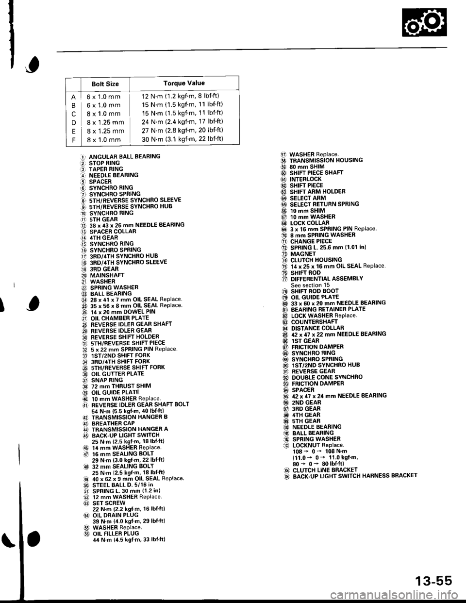
Bolt SizeTorque Value
cn
E
F
6x1.0mm
6x1.0mm
8 x 1.0 mm
8 x '1.25 mm
8 x 1.25 mm
8 x 1,0 mm
12 N.m (1.2 kgnm, 8 lbf'ft)
15 N.m (1.5 kgf'm, 11 lbf ft)
15 N.m (l.5 kgf.m, 11 lbift)
24 N'm (2.4 kgim, 17 lbift)
27 N.m (2.8 kgf.m,20 lbf'ft)
30 N.m (3.1 ksf m. 22 lbift)
5i WASHER Replace.6 TRANSMrssioN HouslNG!9 80 mm SHIM@ SHIFT PIECE SHAFT(6' INTERLOCK@ sHrFr PECE6} SHIFT ARM HOLDER@ seucr nnrvtI9 SELECT RETURN SPRING
@ 10 mm SHIM6, 10 mm WASHER@ LOCK COLLARi6sl 3 x l5 mm SPRING PIN Replace.t0 8 mm SPRING WASHERA) CHANGE PIECEll SPRING L.25.6 mm (1.01 in)'' MAGNET?4) CLUTCH HOUSINGta. 14 x 25 x 16 mm OIL SEAL Replace.A sHrFT BooO D|FFERENT|aL ASSEMBLYSee section 15iIO SHIFT ROD BOOT6 OIL GUIDE PLATE@ 33 x 60 x 20 mm NEEDLE BEASINGO BEARING RETAINER PLATElD LocK WASHER Replace..0 couNTERSHAFIA DISTANCE COLLAR6 & x 4I x 22 mm NEEDLE BEARING6. 1sr GEAR@ FRICTION DAMPERO SYNCHRO RING.d SYNCHRO SPRING@ 1ST/2ND SYNCHRO HUB..9i. REVERSE GEARC) DOUBLE CONE SYNCHROO FRICTION DAMPERS SPACER6 T2 x TI x 24 mm NEEDLE BEARING(!' 2ND GEAR61 3RD GEARiD 4TH GEAR@ 5TH GEAR(O NEEDLE BEARING(10 BALL BEARING@ SPRING WASHERf,o LoCKNUT Replace.108 - 0- 108 N'm111.0- 0* 11.0 kgf m,80* 0- 80lbI.ft)IO CLUTCH LINE BRACKET.d BACK.UP LTGHT SWITCH HARNESS BRACKET
:!, ANGULAR BALL BEABING:2, STOP RING:3] TAPER RING..-I NEEOLE BEARINGl!-- SPACERO SYNCHRO RING? SYNCHRO SPRINGE 5TH/REVERSE SYNCHRO SLEEVE...] sTH/REVERSE SYNCHRO HUB
O SYNCHBO EING.11-r sTH GEAR1A 38 x 43 x 26 mm NEEDLE BEARINGI13) SPACER COLLAR[!] /ITH GEAR.T5) SYNCHRO RING
O SYNCHRO SPRING17 3RD/4TH SYNCHRO HUB
O 3RD/4TH sYNcHRo SLEEVE
ii9 38D GEAR8I MAINSHAFT2i WASHERA SPRING WASH€R?I BALL BEARING.a4, 28 x 41 x 7 mm OIL SEAL Replace..2i 35 x 56 x 8 mm OIL SEAL Replace.t-t 14 x 20 mm DowEL PIN
.'] OIL CHAMBER PLATE
O REVERSE IDLER GEAR SHAFT.iI.., REVERSE IDLER GEAR'd REVERSE SHIFI HOLDERait srH/REVERSE sHIFT PIECE'34 5 x 22 mm SPRING PIN Replace.3' 1ST/2ND SHIFT FORK,34' 3RD/4TH SHIFT FORKi9t) srH/nevense sstrr ronx33 OIL GUTTER PLATE!' SNAP RING3d 72 mm THRUST SHIM
@ OIL GUIDE PLATE4t 10 mm WASHER Replaceti REVERSE TDLER GEAR SHAFT BoLT54 N.m {5.5 kgf m, 40lbIft)4N TBANSMISSION HANGER B43] BREATHER CAPA,J TRANSMISSION HANGER AIT' BACK-UP LIGHT SWITCH
I
25 N.m {2.5 kgl.m, 18lblftl14 mm WASHER RePlaceaO 14 mmtt 16 mm16 mm SEALING BOLT29 N.m (3.0 kgf m,22 lbf ft):4s) 32 mm SEALING BoLT25 N m 12.5 kgl m, 18 lbl'ft)40 x 62 x I mm OIL SEAL ReplaceSTEEL BALL D.5/15 iNSPRING L. 30 mm {1.2 in)12 mm WASHER Replace.SET SCREW22 N.m {2.2 kg{ m, 16 lbl ftlOIL DRAIN PLUG39 N.m {4.0 kgf m, 29lbtftlWASHER Replace.OIL FILLER PLUG4,t N.m {4.5 kgl m, 33 lblftl
.!rl00
@l
13-55
Page 762 of 2189

Electrical Troubleshooting ('gg - 00 Models)
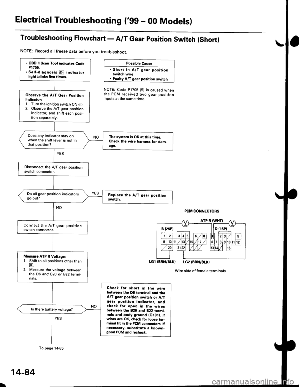
Troubleshooting Flowchart - A/T Gear position Switch (Short)
NOTE: Record all freeze data before you troubleshoot.
Po$ible Cause
' Short in A/T go.r positionswhch wire. Faulty A/T goar position switch
NOTE: Code P1705 (5)the PCM received twoinputs at the same time.
is caused whengear position
PCM CONNECTORS
LGl (BRN/BLK) LG2 (BRN/BLKI
Wire side of femaleterminals
B {25P1 llD (16P1
. OBD ll Scan Tool indicrtB CodeP1?05.. Solt-diagno3i3 E indicatorlight blink. tive times.
Observo the A/T Gear PositionIndicetori1. Turn the ignition switch ON fit).2. Observe the lVT gear positionindicator, and shift each posi,!on separately.
Does any indicator stay onwhen the shift lever is not inthat position?
The sFtom is OK at thi3 time.Check the wi.e harness for dam-aga.
Do all gear position indicatorsgo out?
Moasure ATP R Voltage:1. Shift to all positions otherthanE.2. Measure the voltage betweenthe DG and 82O o( 822 terfii-nats.
Check tor short in the wirebatwoen tha DB terminal and theA/T go.r porhion switch or A/Tg6ar po3ition indicator, andchock for opon in the wiresbetween the B20 and B22 t€rmi-n.ls and body ground (G10 . tfwir€c rro OK, chsck fo. loo3e tel-ftinal fit in the FCM connectors. llnoceisary, substiiute e known-good FCM and r€check.
ls there battery voltage?
To page 14-85
\
14-84
Page 807 of 2189

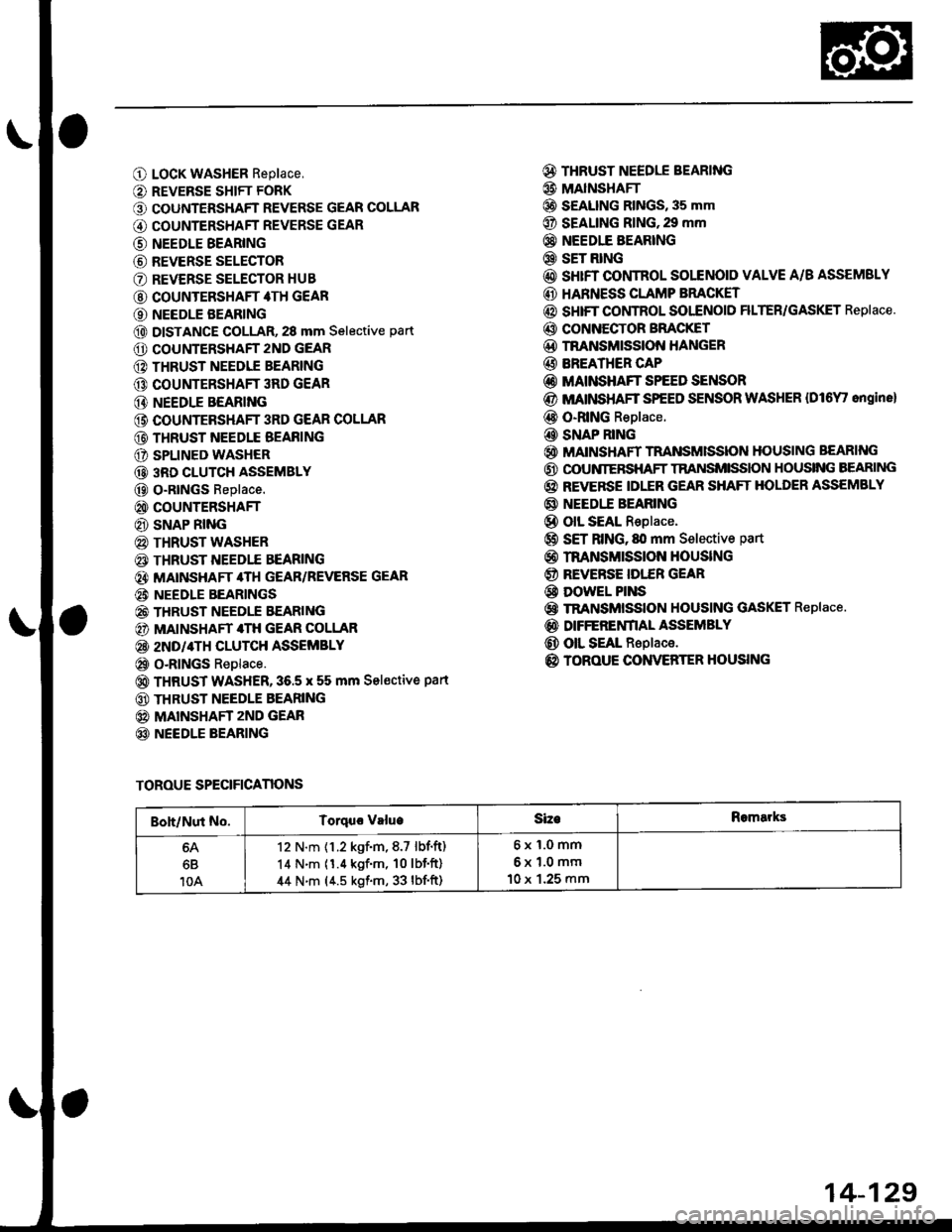
O LocK WASHER Replace,
O REVERSE SHIFT FORK
O COUNTERSHAFT REVERSE GEAR COLLAR
G) COUNTERSHAFT REVERSE GEAR
@ NEEDLE BEARING
@ REVERSE SELECTOR
O REVERSE SELECTOR HUB
@ COUNTERSHAFT 4TH GEAR
O NEEDLE BEARING
@ DISTANCE GOLLAR, 28 mm Selective part
O COUNTERSHAFT 2ND GEAR
@ THRUST NEEDIE BEARING
@ COUNTERSHAFT 3RD GEAR
@ NEEDLE BEARING
@ COUNTEBSHAFT 3RD GEAR COLLAR
@ THRUST NEEDLE BEAFING
O SPLINED WASHER
@ 3RD CLUTCH ASSEMBLY
@ O-RtNGs Replace.
@ COUNTERSHAFT
@ SNAP RING
@ THRUST WASHER
€) THRUST NEEDTE BEARING
@} MATNSHAFT 4TH GEAR/REVERSE GEAR
@i NEEDLE BEARINGS
@ THRUST NEEDLE EEARING
@) MAINSHAFT 4TH GEAR COLLAR
@ 2ND/4TH CLUTCH ASSEMBLY
@ o-RlNGs Replace.
@ THRUST WASHER,36.5 x 55 mm Sel€ctive part
@ THRUST NEEDLE BEARING
@ MAINSHAFT zND GEAR
@ NEEDLE BEARING
@ THRUST NEEDLE BEARING
@ MAINSHAFI
@ S€ALING RINGS, 35 mm
@ SEALING RING,29 mm
@} NEEDIE BEARING
@ SET RING
@ sHrFT CONTROL SOLENOID VALVE A/B ASSEMSLY
@ HARNESS CLAMP BRACKET
@ SHIFT COI,ITROL SOI"ENOID FILTER/GASKET Replace.
@ CONNECTOR BFACKET
@D TNANSMISSION HANGER
@ BREATHER CAP
@ MAINSHAFT SPEED SENSOR
@ MATNSHAFT SPEED SENSOR WASHER {Dl6Y' ongine}
@ O-RING Replace.
@ SNAP RING
@ MAINSHAFT TRANSMISSION HOUSING BEARING
@ OOUNIERSHAFT TRANSMISSION HOUSING BEARING
@ REVERSE IDLER GEAR SHAFT HOLDER ASSEMBLY
@ NEEDI.E BEARING
@ olL SEAL Replace.
@ SET RING, fll mm Selective part
@ rnANsMrssloN HouslNG
@ REVERSE IDI."ER GEAR
@ DowEL PINS
@ TRANSMISSION HOUSING GASKET Replace.
@ DIFFERENfIAL ASSEMBLY
@ OIL SEAL Replace.
@ TOROUE CONVERTER HOUSING
TOROUE SPECIFICANONS
Boh/Nut No.Torquo valueSizeRomarks
6B
10A
12 N.m {1.2 kgf.m,8.7 lbf.ft)
14 N.m (1.4 kgf'm, 10lbf'ft)
44 N.m (4.5 kgf.m, 33 lbf'ft)
6x1.0mm
6x1.0mm
10 x 1.25 mm
14-129
Page 927 of 2189

Electrical Troubleshooting (,96 - 9g Modelsl
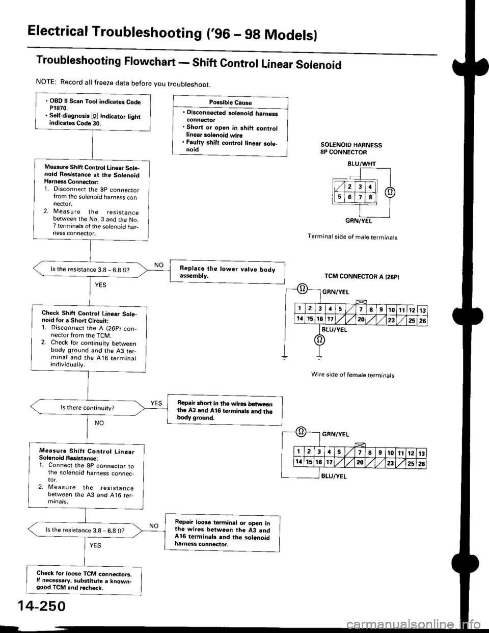
Troubleshooting Flowchart - Shift Control Linear Solenoid
Possible Cause
' Disconnected 3olenoid h.rn€isconnoctor. Short or open in 3hift controllinear solenoid wire. Faulty shift control linear sole-noidSOLENOID HARNESS8P CONNECTOR
Terminal stde of male terminals
Wire side of female terminals
8LU/YEL
NOTE: Record all freeze data before you troubleshoot.
. OBD ll Scan Toot indicates CodeP1870.. Selt-dirgnosis [d indic.tor tightindicatos Code 30.
Measure Shift Control Linoar Sole-noid Resistance at the SolenoidHarness Connector:1. Disconnect the 8p connectorfrom the solenoid harness connector.2, Measu re the resistancebetlveen the No. 3 and the No.7 terminals ofthe solenoid haFness connector.
ls the resistance 3.8 - 6.8 O?
Check Shift Controt Linear Sote-noid for a Short Circuit:1. Disconnect the A (26p) con,nector from the TCM.2. Check for continuity betweenbody ground and the A3 terminal and the A16 terminalindividually.
Repair shon in tho wire6 betweonthe A3 and A16 termin.ts lnd thobody ground.
Measure Shitt Control Line.rSolenoid Resistance:1. Connect the 8P connector tothe solenoid harness connec,tor.2, Meas u re the resistancebetween the 43 and A16 ter-
Repair loose terminal oa open inthe wires between the 43 andA16 terminal3 and the solenoidharness connector.
ls the resistance 3.8 6.8 O?
Chock for loose TCM connectorc.ll necessary, substitute a known-good TCM and recheck.
BLU/WHT
GRN/YEL
TCM CONNECTOR A I26PI
GRN/YEL
ll 12l:
IriGlx
1578910111213
172t)232526
14-250
Page 928 of 2189

Troub|eshootingF|owchart_PH-PLControJLinearSo|enoid
NOTE| Record all treeze data before you troubleshoot
Possible cause
' Disconnected solenoid harness
connectof. Short or oPen in PH_PL control
linear solenoid wire. Faulty PH-PL control linear sole_
noidSOLENOIO HARNESS8P CONNECTOR
GRN/WHT
Terminal side of male termlnals
Wire side ol female terminals
. OBD ll Scan Tool indicates Codo
P1873.. sef-diagnosis E indicalor light
indicat6 Code 31.
Measure PH-PL Control Linear
Solenoid Resistance at the Sole_
noid Hatness Connectot:1. Disconnect the 8P connector
from the solenoid harness con-
nector,2. Measure the resistance
between the No 2 and the No.
6 terminals ofthe solenoid har
ness connector'
ls the resistance 3.8 - 6.8 0?
Check PH-PL Control Lineer
Solenoid for a Short Circuit:
1. Disconnect the A 126P) con-
nector lrom the TCM
2. Check for continuity between
body ground and the A2 ter
minal and the A15 terminal
individually.
Repair short in th€ wires
between the A2 and A15 lermi_
nals and the body glound.
Measute PH-PL Control Linear
Solenoid Resi3tance:1. Connect the 8P connector to
the solenoid harness connec-
tor,2, Meas u re the reslslance
between the ,q2 and A15 ter_
Rep.il loose tetminal or oPen in
th6 wires betwccn the A2 and
A15 lerminals and the solenoid
harness conn€ctol.
lsthe resistance 3.8-6 8 O?
Check for loose TCM connactors
lf neceasery, Substitute a known-good TCM and rechock.
PNK/BLK
TCM CONNECTOR A (26P)
oPNK/BLK
I234578I10l11213
11't5161720/,,/232526
IGRN/wHr
o
*r}l
t'T,
E[
PNK/8LK
3a5I910111213
1620232526
GRN/WHT
14-251
Page 929 of 2189

Electrical Troubleshooting ('96 - gg Modelsl
Troubleshooting Flowchart - start clutch control Linear solenoid
NOTE: Record all freeze data before you t.oubleshoot.
Po$iblo C.u.o
' Di3aonnoctod solanoid harncatconnactol. Short or opon in start clutchcontrol linoar tolanoid wira. Faulty ttart clutch control lino.rsolanoid
SOLENOID HARNESS8P CONNECTOR
Terminal side of male terminals
Wire side of female terminals
. OBO ll Scan Tool indicatG CodeP1879.. Self-dilgno.is E indicator lightindiclt$ Code 32.
Me.suro Sta.t Clutch ControlLinear Solenoid Rosirtrnco st th.Solenoid Hrrn6rs Connecto.:1. Disconnect the 8P connectorfrom the solenoid harness con-nector.2, Measure the resistancebetween the No. 4 and the No.8 terminals otthe solenoid har-ness connectot.
ls the resistance 3.8 - 6.8 0?
Chock Start Clutch Control Lin-oar Solenoid tor a Short Circuit:1. Disconnect the A (26p) con,nector from the TcM.2. Check lor continuity betweenbody ground and the A1 ter-rninal and lhe Al il terminalindividually.
Raprir 3hort in tha wira3b.ftvcen tho A1 .nd Atil t .mi.n.l. .nd thr body ground.
Measure Stan Clutch Cont.olLineer Solenoid F6aist.ncei1. Connect the 8P connector tothe solenoid harness connec-tor.2. Meas u re the resistancebetween the 41 and Al4 ter-minals,
Rcplir loose tcrminal or oDcn inthG wiras b.tween the Al rndAla torminal3 rnd tha 3olanoidhamaas connactor.
ls the resistance 3.8- 6.8 O?
Check for loose TCM connecto.s.lf necessary, substitute a known-good TCM and iecheck.
YEL
PNK/BLU
TCM CONNECTOR A I26P}
-{r-
E
PNK/BLU
23a51I910ll1213
a15t61'20a252G
YEL
14-252