Page 1539 of 2189

t
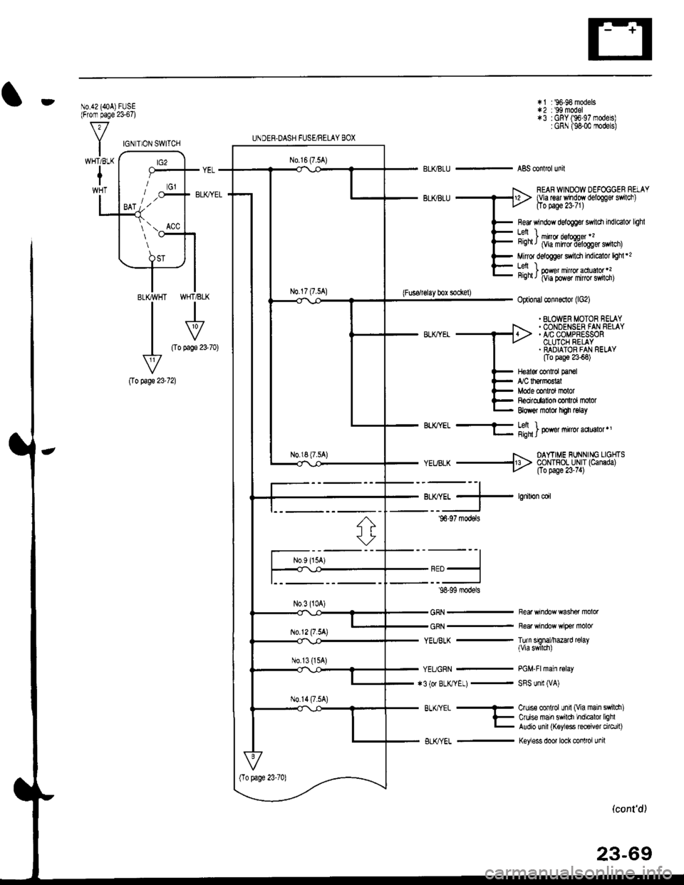
BLI(BLU - ABS controlunit
r 96'9€ models: 99 modol: GRY (96-97 models: GRN (9&00 models
Rear window d8loloer swilch indicalo. l€ht
::: ) mirroa d€loQor r?Hrgn, Ma miror i;logger sYritch)
Miror dolog06r $ tdr indicalor lighl'2
191 ) oo*e, ri,,o, "qraor',hEn, ivra pow mircr sMdr
odional conna.ior 1lG2)
*2*3
REAR WINDOW DEFOGGER RELAY{Via Gar wndow deloggot sw ch)fro page 23-71 )
N0.42 (40A)FUSE(Frofir page 23.67)
WHTi BLK
t
lFusdrelay bor socl(el)WHT/BLK
I
V
fro page 23'70)
Ipag6 23-0o
. BLOWER MOTOR FELAY. CONDETISER FAN RETAY. ,VC COMPRESSORCLWCH RELAY. NAONTOR FAN RELAY0o pag€ 2368)
12)Heal€r conlrol Pan6l,ryC her|lDshlMode conlrol molorReorolalion conlol molorAow€r molor iEh aelay
YEUBLK -
YEUGRN -
:rl l^r A k/YF l -
B./"|YEL - Ctr|s€ conlrcl Jn (Via main swildr)
l- C'uEe ma'4 swildr 'ndicalot lEhlL Audio unil (K€y oss rece'ver drol4)
BLKryEL - Kevless door tock conlroi unit
UNDER.DASH FUSE/RELAY BOX
N0.16 (7.5A)
(To page 23'70)
No.l2 (7.5A)
N0.13 (15A)
N0.14 (7.54)
IGN TION SWITCH
BA1 ;.'
1 '.._ ACC
q, (/vrr - |.fi II ::: I mrcr mircr aqua|ol'r
F DAY'IME FUNNING LIGHISvELrtsLK -113> CONTFOL UN|T (Ceneda)t'- (f o We 23-71)
,F1J- ,n*,"',
'96-97 mod6ls
""j
'98-99 models
GRN -
GRN _
Rear window washer molof
Rear window wiper molor
Turn srgnal/hazard relay(Viaswilch)
PGM-Flmain relay
SRS unii (VA)
(cont'd)
23-69
Page 1544 of 2189

Power Distribution
Circuit ldentification (cont'd)
Canada:
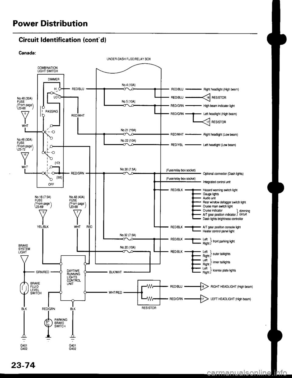
COMBINATIONLIGHT SWITCH
N0.48 {30A)
RED/BLU - Right headlighl (High boam)
FEDiBLU ----< REstsTOR
REo/GRN - HiJh beam indicator lighl
BEo/GRN - Left headlighl iH,gh beam)
L
Fight headlight {Low beam)
FEo/YEL - L€ll headlight (Low beam)
(Fuse/lelay box sockel)Optional conneclor (oash lighs)
Inleg6led conlrcl unil
- Hazard wanirE swilch lighl
i- Gauge lEhts
l- Audio unil
l- Re& Yrindow delogg8r swili
t- Ctuise main swrdr ligh
l- C/uise indEator l
E g"ffiry:'l,:1':::1
Refi window delog$r swildr light
Ctuise indicalor 1 dimming,T geal posilion indicator J circu(Dasn lghls brignmess co oller
BRAKESYSTEMLIGHT
V
I
l- GFf
,,4,,0*,lf tIFLUDII ,j I LEVEL
Y
SWTCH
I8LKI
I
I
I:
G401G402
REo/BLK - l/T ged position console lqhl- Hqalor codrot panel tighl
REO/BLK -F- Lefi ) .l- g;n1J lron 9arrn! qm
FEDiBLK + Letl I
F Rqn J ouer larrqns
- I Al, I
{- i'-;*; inne' raittiotts
E fifi]t'"nt"o't't'sn"
*ro,rru -$ RcHT HEADLIGHT (Hrgh beam)
BEDiGRN -+ LEFI H EADLIGHT (High beam)
I BLK
IIPARKING IEFAKE IswrrcH I
I:
G401G402
UNDER,DASH FUSE/RELAY 8OX
lo| | PASSTNGto
/Fforn page\\a-68 l
N0.48 {304)FUSE/From page\\23-72 )
N0.18 (7.54)FUSE/From page \\?3-69 J
v
YIYEUBLK
N0.48 (40A)FUSE/From paqe \\23-68 - ,/
RED6RN
23-74
Page 1552 of 2189
Ground Distribution
Circuit ldentification (cont'dl
'99-00 models:(Wilholl ABS)
r'1BL( -< 6 | c40. tFror oaoe 23-BC. II
L
E
UNDEF.H@DFUSF]RELAY BOX
_::I
A,/I gefi posilion swilchELD unil
Servi@ check connector
BL-_14BL- rl--{ry--Browe,mororreray
L4 ,r^ -.;--a-r,* -11-51 BLK - Hearer conrror o6nt n"*-fi-+aLx-lfuBLK- Hearer conrror panel
eLx -iff BLK - ff;?,m",:[:' "n'
or*
ABS glmp motor
_trl
G501
Pos€r door lock cortaol unitDivers door lock aclualorDriver's door lock switchLefl miror delogger
BLK --.+t _
F J Power wndos man swdch
-. Dive/s Fo*gr window motor
TBLK -.1 F--{ BLK - Fighr.niror detogger
tr
tr
E : Healer sub-haness A
El : Healer sub'harress B
: Floor wire hamess
: Drve/sdoorwife haness
-
|,-"*T-"^tl I
vl-L"."
G551
ort,
El ' Main *it" hanes
E : Dashboafd wirc harness
23-82
@ Passenger's doof w're hamess
Page 1553 of 2189
G601High molnl brake lighlR€ar window wper molor
Bigh mounl brake lighlRear window wiper molor
TrLrnk laldl swilch
ouo,
l"fn, ) o*"' ''*'nnt"
l",$') 'nnt' '"t'n"'
lt$|n') ''"nt"o'"'t,'nn"
Tronk lalci switchHigh mounl brake lighl
(coupe/sedan : 96-98 models)
G601
li|n') o*".'tt'nn''
l[., ] 'nn"' 't*'n*"
.,"'jn, ) """n" o'"t" ''nnt"
Trunk laldr swlcll
(cont'd)
BLK *'lli.,ilJ:"f_'$l
{Sedan : 99 00 models)
E :Fearwrehaness
E , H"t"h nit" h"tnes"
23-83
Page 1670 of 2189
Rear Window Defogger
Gomponent Location Index
36 - 98 modols:
UNDER.DASH FUSE/RELAY BOX
REAR WINDOW DEFOGGER SWITCHInput Test, page 23-203
REAR WINOOW DEFOGGERRELAYTest, page 23-86
REAR WINOOW OEFOGGERFunction Test, page 23'202Defogger Wire Repair. page 23 202
23-200
Page 1674 of 2189

Rear Window Defogger
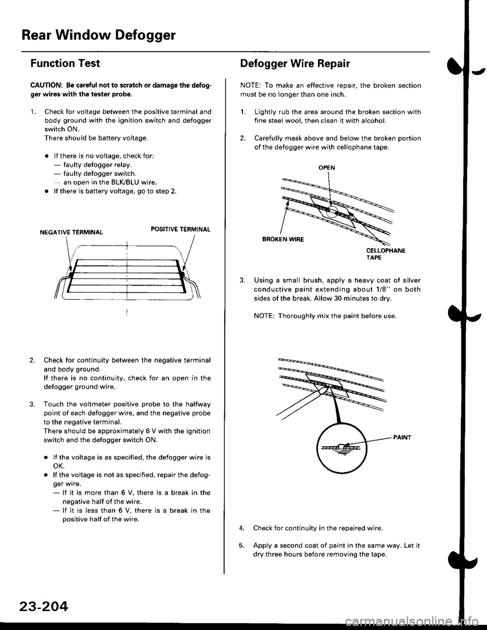
Function Test
CAUTION: Bs careful nol to scralch or damage the defog-
ger wires with the tester probe,
'1. Check for voltage between the positive terminal and
body ground with the ignition switch and defogger
switch ON.
There should be banery voltage.
. lf there is no voltage, check for:- faulty defogger relay.- faulty defogger switch.
an ooen in the BLK,/BLU wire.
. lf there is battery voltage, go to step 2.
POSITIVE TERMINAL
2. Check for continuity between the negative terminal
and body ground.
lf there is no continuity, check for an open in the
defogger ground wire.
Touch the voltmeter positive probe to the halfway
point of each defogger wire, and the negative probe
to the negative terminal.
There should be approximately 6 V with the ignition
switch and the defogger switch ON.
. lf the voltage is as specified. the defogger wire is
oK.
. lf thevoltage is not as specified, repairthe defog-
ger wrre.- lf it is more than 6 V, there is
negative half of the wire.- lf it is less than 6 V, there is
positive half of the wire.
a break in the
a break in the
23-204
OPEN
?
Defogger Wire Repair
NOTE: To make an effective repair, the broken section
must be no longer than one inch.
1, Lightly rub the area around the broken section with
fine steel wool, then clean it with alcohol.
2. Carefully mask above and below the broken portion
of the defogger wire with cellophane tape.
CELLOPHANETAPE
Using a small brush, apply a heavy coat of silver
conductive paint extending about 1/8" on both
sides of the break. Allow 30 minutes to dry.
NOTE: Thoroughly mix the paint before use.
Check for continuity in the repaired wire.
Apply a second coat of paint in the same way. Let it
dry three hours before removing the tape.
Page 1675 of 2189
Switch Input Test
CAUTION: Be careful not to damagc the rear window
defogger switch or the center panel when prying the
switch out.
NOTE: Before testing, check for blown No. 16 (7.5 A)
fuse in the under-dash fuse/relay box,
1. Pry the switch out of the center panel (see section 20).
2. Disconnect the 5P connector from the switch.
3. Turn the jgnition switch ON (ll), and check the voltage
between the BLVBLU {+) and the BLK (-)terminals.
There should be battery voltage
. lf there is no voltage, check for an open in the
BLVBLU wire.
. lfthere is baftery voltage, go to step 4.
Wire side of famale terminals
connect a jumper wire between the BLK/BLU and
the BLU/YEL terminals.
Turn the ignition switch ON (ll), and check that the
rear window defogger works; if it does. replace the
defogger switch.
4.
RED
l-
23-205
Page 1684 of 2189
Wipers/Washers
Component Location Index
SBS components are located in this area, Review the SRS component locations, precautions, and procedures in the SRSsection (241 betore performing repairs or service.
WIPER/WASHER SWITCHTest, page 23-215REAR WINDOW WIPERMOTOR lHatchback)Test, page 23'216WINDSHIELD WIPER ARMS/BLADES
WINDSHIELD WIPER MOTORTest, page 23-215
WASHER FLUIDRESERVOIR
WASHER MOTOR {Hatchback)Test, page 23'216
INTERMITTENT WIPER RELAYCIRCUIT (ln the integratedcontrol unit)
t_l
Iilr
i
T
23-214