Page 1180 of 2189
Rear Brake Disc
Disc Runout Inspection
1.Loosen the front wheel nuts slightly, then raise thevehicle, and suppon it on safety stands. Removethe front wheels.
Remove the brake pads (see page 19-24).
Inspect the disc surface for damage and cracks.Clean the disc thoaoughly, and remove a
rust.
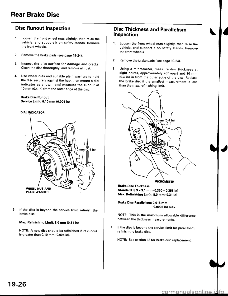
Use wheel nuts and suitable plain washers to holdthe disc securely against the hub. then mount a dialindicator as shown. and measure the runout at10 mm (0.4 in) from the outer edge of the disc.
Brake Disc Runout:
Service Limit:0.10 mm {0.00,t in)
5. lf the disc is beyond the service limit, refinish thebrake disc,
Max. Retinishing Limit: 8.0 mm {0.31 in)
NOTE: A new disc should be refinished if its runoutis greater than 0.10 mm (0.004 in).
19-26
Disc Thickness and Parallelism
Inspection
1. Loosen the front wheel nuts slightly, then raise thevehicle, and support it on safety stands. Removethe front wh6els.
2. Remove the brake pads (see page j9-24).
3. Using a micrometer. measure disc thickness aterght points, approximately 45" apart and 1o mm{0.4 in) in from the outer edge of the disc. Replacethe brake disc if the smallest measurement is lessthan the max. refinishing limit.
Brake Disc Thickness:
Standard: 8.9 - 9.1 mm (0.350 - 0.358 in)Max. Rsfinishing Limit: 8.0 mm {0.31 in}
Brake Disc Parallelirm: 0.015 mm(0.0006 inl msx.
NOTE; This is the maximum allowable differencebetween the thickness measurements.
4. lf the disc is beyond the service limit for Darallelism.refinish the brake disc.
NOTE; See section 18 for brake disc replacement.
Page 1181 of 2189
Rear Brake Caliper
Disassembly
@f l',lever use an air hose or dry brush to clean
assemblies.
. Use an OsHA-approved vacuum cleaner to
brake
avoid
breathing brake dust.
. Contaminated brake discs or pads reduce stopping
ability.
CAUTION:
. Do not spill brake tluid on the cal; h may damage the
paint; if brake fluid does contact the paint, wash ii
ofl immediatelY with water.
. To prevent spills, cover the hose ioints whh rags or
shop tow€ls.
. Clean all parts in brake fluid and air dry; blow out all
passagss with complessed air.
1. Remove the caliper shield (see page 19-24).
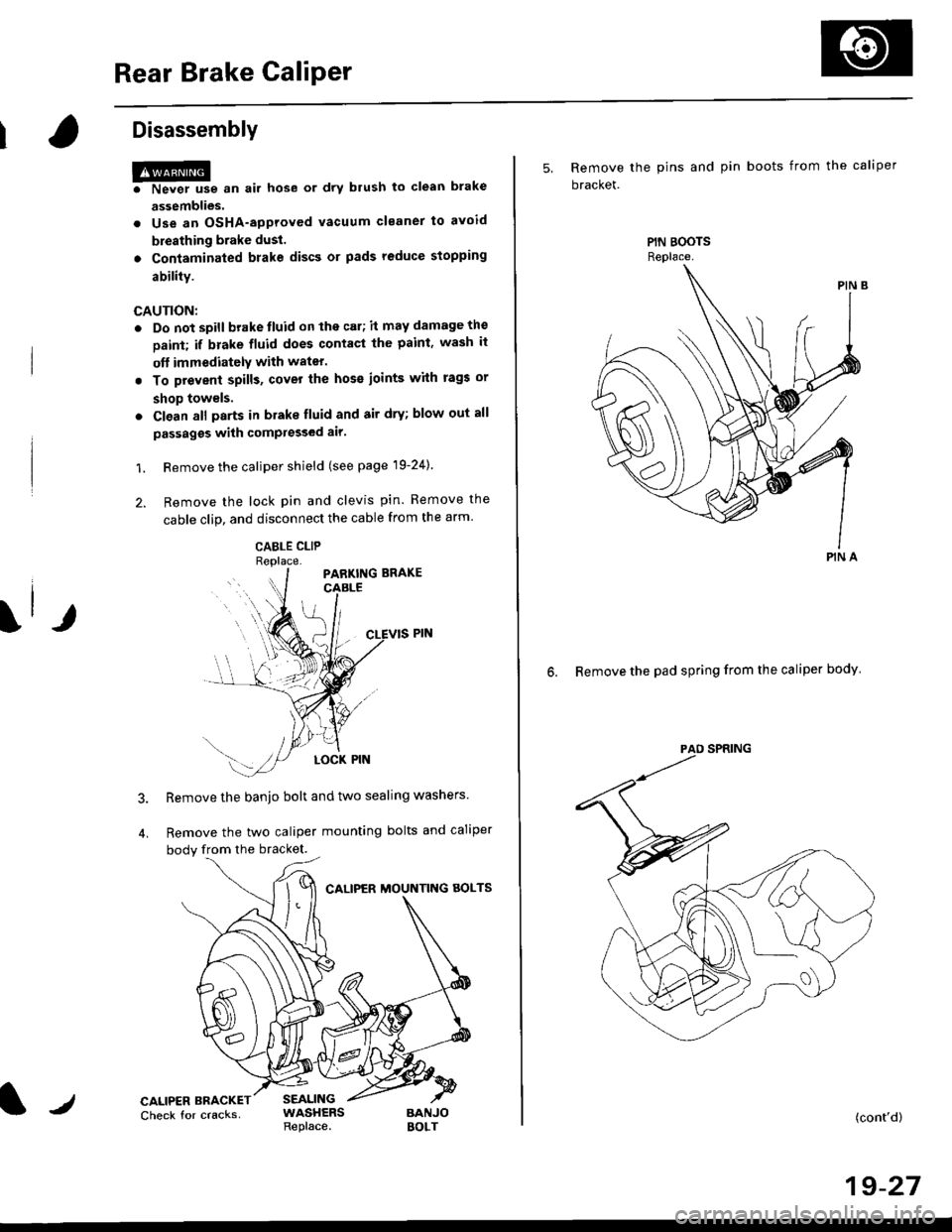
2. Remove the lock pin and clevis pin. Remove the
cable clip, and disconnect the cable from the arm
CABLE CLIP
Remove the banjo bolt and two sealing washers
Remove the two caliper mounting bolts and caliper
body from the bracket.
CALIPER MOUNTNG AOLTS
CALIPER BRACKETCheck for cracksSEALINGWASHERSReplace.BANJOBOLT
5, Remove the pins and pin boots from the caliper
bracket.
6. Remove the pad spring from the caliper body
PIN A
(cont'd)
19-27
Page 1188 of 2189
Rear Brake Caliper
Reassembly (cont'dl
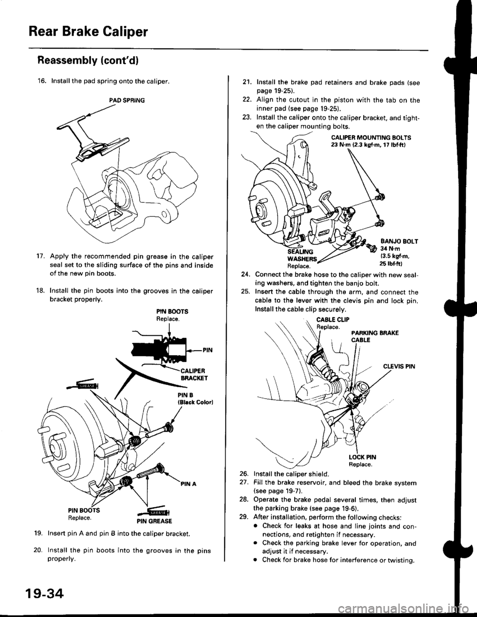
'16. Installthe pad spring onto the caliper.
Apply the recommended pin groase in the caliper
seal set to the sliding surface of the pins and inside
of the new pin boots.
Install the pin boots into the grooves in the caliper
bracket properly.
PIN BOOTSReplsce.
(Bl.ck Colorl
PINRepl6ce.
19. Insert pin A and pin B into the caliper bracket.
20. Install the pin boots into the grooves in thepropefly.
PAD SPRING
11.
PIN GREASE
19-34
pr ns
22.
21. Install the brake pad retainers and brake pads (see
page 19-25).
Align the cutout in the piston with the tab on the
inner pad (see page 19-25).
Install the caliper onto the caliper bracket. and tight-
en the caliper mounting bolts.
CALIPER MOUNTING BOLTS23 N.m {2.3 kg{.m. 17 lbf.ft)
WASHERSReplace.
BANJO BOLT34 N.m13.5 kg{.m.25 rbtft)
24.Connect the brake hose to the caliper with new seal,
ing washers, and tighten the banjo bolt,
Insert ths cable through the arm, and connect the
cabls to the lever with the clevis pin and lock pin.
Install the cable clip securely.
CLEVIS PIN
-t
//t
LOCK PINRoplace.
26. Install the caliDer shield.
27. Fill the brake reservoir, and bleed the brake svstem(see page 19-71.
28. Operate the brake pedal several times, then adjust
the parking brake (see page 19-6).
29. After installation, perform the following checks:. Check for leaks at hose and line joints and con-nections, and retighten if necessary.. Check the parking brake lever for operation, and
adjust it if necessary.
. Check for brake hose for interference or twistinq.
Page 1250 of 2189
Doors
Glass/Regulator Replacement (cont'dl
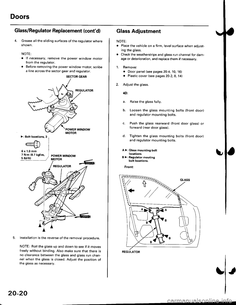
Grease all the sliding surfaces of the regulator where
shown.
NOTE:
. lf necessary, remove the power window motorfrom the regulator.
. Before removing the power window motor, scribe
a line across the sector gear and regulator.
REGULATOR
5. Installation is the reverse of the removal orocedure.
NOTE: Roll the glass up and down to see if it moves
freely without binding. Also make sure that there isno clearance between the glass and glass run chan-nel when the glass is closed. Adjust the position ofthe glass as necessary.
SECTOR GEAR
20-20
Glass Adjustment
NOTE:
. Place the vehicle on a firm, level surface when adjust-
ing the glass.
. Check the weatherstrips and glass run channel for dam-
age or deterioration, and replace them if necessary.
1. Remove:
. Door panel (see pages 20-4, 10, 16). Plastic cover (see pages 20-2,8, 14)
2. Adjust the glass.
4D:
Raise the glass fully.
Loosen the glass mounting bolts (front door)
and regulator mounting bolts.
Push the glass rearward (front door glass) or
iorward (rear door glass).
Tighten the glass mounting bolts (front door)
and regulator mounting bolts.
A >: Gl.3s mounting boltlocations.B >: Regulrtor moutingbolt loc.tions.
Front:
a.
b.
d.
REGULATOR
Page 1251 of 2189
b
GLASS
REGULATOR
+"+
J\
e. Loosen the front channel mounting bolts (front
door) or rear channel mounting bolt lrear
ooor,,
f. Lower the glass.
g. Push the front or rear channels against the
glass, then tighten the mounting bolts.
>: Front and rearchannel mountingbolt locations
Front:
\
Rear:
2DI3D:
b.
Raise the glass as far up as possible, and hold
it against the glass run channel.
Loosen the roller guide bolts, and adjust the
glass so it is parallel with the glass run channel.
GLASS RUNCHANNEL
ROLLER GUIDE BOLTS
(cont'd)
20-21
Page 1253 of 2189
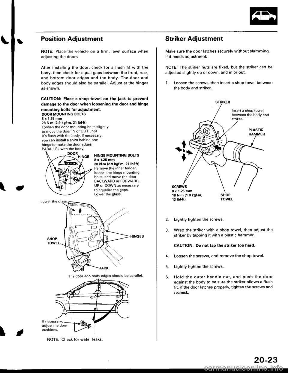
bPosition Adjustment
NOTE: Place the vehicle on a firm, level surface when
adjusting the doors.
After installing the door, check for a flush fit with the
body, then check for equal gaps between the front, rear,
and bottom door edges and the body. The door and
body edges should also be parallel. Adjust at the hinges
as shown,
CAUTION: Place a shop towel on the iack to prevent
damage to the door when loosening the door and hinge
mounting bohs for adiustment.
DOOR MOUNTING BOLTS8 x 1.25 mm28 N.m {2.9 kgf.m.21 lbt'ft}Loosen the door mounting bolts slightly
to move the door lN or OUT until
it's flush with the body. lf necessary,
vou can installa shim behind one
hinge to make the door edgesPARALLEL with the body.
J
HINGE MOUNTING BOLTSI x 1.25 mm28 N.m (2.9 kgf.m,21 lbtft)Remove the inner fender,loosen the hinge mountingbolts, and move the doorBACKWARD or FORWARD,UP or DOWN as necessaryto equalize the gaps.Lower the glass.
\
The door and body edges should be parallel-
ifF t
NOTE: Check for water leaks.
20-23
Striker Adjustment
lvlake sure the door latches securely without slamming.
lf it needs adjustment:
NOTE; The striker nuts are fixed, but the striker can be
adjusted slightly up or down, and in or out.
'L Loosen the screws, then insert a shop towel between
the body and striker.
Insert a shop towelbetween the body and
sc8Ews8 x 1.25 mm18 N.m (1.8 kgf.m,13 tbtftl
PLASTIC
2. Lightly tighten the screws.
3. Wrap the striker with a shop towel, then adjust the
striker by tapping it with a plastic hammer.
CAUTION: Do not tap the striker too hard.
4. Loosen the screws. and remove the shop towel.
Lightly tighten the screws.
Hold the outer handle out, and push the door
against the body to be sure the striker allows a flush
fit. lf the door latches properly, tighten the screws and
recheck.
5.
Page 1284 of 2189
Moonroof
Motor, Drain Tube and Frame Replacement
CAUTION:
. Put on gloves to protecl your hands.
. Be careful not to damage the seats, dashboard and other interior trim.
'1. Remove the headliner {see page 20-64).
2. Disconnect the motor connector and glass position switch connector.
NOTE: When removing the motor, detach the connector from the frame, remove the bolts and nuts, then remove the
motor.
3. Remove the glass {see page 20-52).
4. Disconnect the drain tubes, and detach the ceiling light harness.
5. Remove the frame mounting bolts.
NOTE;
. An assistant is helpful when removing the bolts.
. Remove the front bolts last.
6. Detach the rear hooks by moving the frame forward, then remove the frame.
BOLT6x1.0mm9.8 N.m {1.0 kgt m,7.2 tht.hl
6x1.0mm9.8 N m (1.0 kgl.m, 7.2 lbtft)
20-54
\
Page 1289 of 2189
Interior Trim
tReplacement
CAUTION:
. Put on gloves to protect your hands.
o When prying with a flat-tip screwdriver, wrap it with protective tape to prevent damage.
NOTE: Take care not to bend or scratch the trim and panels.
4D:
>: Clip locationsa>,2c >,2'lo >,2E >,2
r*'" n t-lt't
\wi, i
' l ll/
_tr* @,
CENTER PILLARUPPER TRIMREAR PILLARTRIM
LOCK CYLINDER TRIM
tl'
I
E'vBELT UPPERANCHOR(see page 20-85)
Disconnect thehigh mount brakelrght connector.
T SIDE TRIMRemove the rear seat cushion and rearseat side bolster lsee page 20-19]'.
)
lnstallation is the reverse of the removal procedure.
NOTE:
. lf necessary, replace any damaged clips.. Before installing the front seat belt upper anchor
and rear shelf. make sure there are no twists or
kinks in the seat belts.(cont'd)
B>,6
REAR SHELF
k"si
fEFT KICKPANEL
20-59