1999 HONDA CIVIC Power
[x] Cancel search: PowerPage 360 of 2189
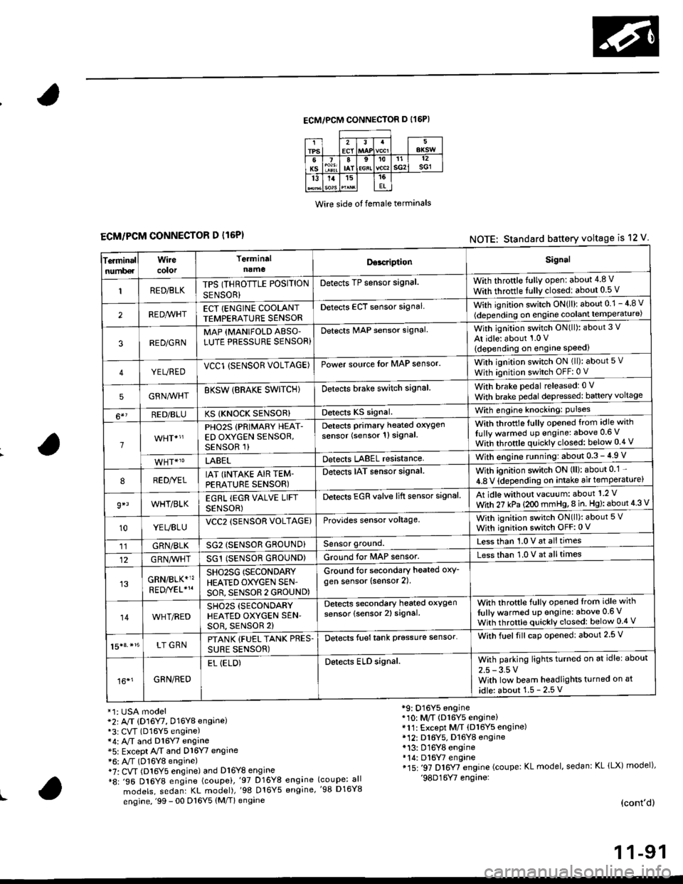
ECM/PCM CONNECTOR D I16P)
Wire side ot female terminals
ECM/PCM CONNECTOR D l16P)NOTE: Standard battery voltage is 12 V
Te.minalnumb€r
Wirecolor
Terminaln!meDor.riptionSignal
RED/BLKTPS (THROTTLE POSITION
SENSOR}
Detects TP sensor signal.With throttle fully open: about 4.8 V
With throttle fully closedl about 0.5 V
REDA/VHTECT {ENGINE COOLANTTEMPERATURE SENSORDetects ECT sensor signalWith ignition switch ON{ll): about 0.1 - 4 8 v
(depending on engine coolant lempe ratu re)
3RED/G RNMAP {MANIFOLD ABSO'LUTE PRESSURE SENSOR}Detects MAP sensor signal.With ignition switch ON(ll): about 3 V
At idle: about 1.0 V
{depending on engine speed)
YEUREDVCCl (SENSOR VOLTAGE)Power source lor MAP sensor.With ignition switch ON (ll): about 5 v
With ignition switch OFF: 0 V
5GRNMHTBKSW {BRAKE SWITCHIDetects brake switch signalWith brake pedal released: 0 v
With brake pedal depressed: baftery voltage
6*?RED/BLUKS {KNOCK SENSOR}Detects KS signal.With engine knocking: Pulses
1
PHO2S (PRIMARY HEAT-ED OXYGEN SENSOR,SENSOR 1)
Detects Primary heated oxygen
sensor (sensor 1l signal
With throttle fullv opened from idle with
Iully warmod up engine: above 0.6 V
With throttle quickly closed: below 0.4 v
LABELDetects LABEL resistanceWith engine r!nning:about 0.3 - 4.9 V
8RED//ELIAT (INTAKE AIR TEM-PERATURE SENSOR)
Detects IAT sensor signal.With ignition switch ON (ll): about 0 1 -
4.8 V {depending on intake air temperature)
9*lWHT/BLKEGRL iEGR VALVE LIFT
SENSOR)
Detects EGR valve lift sensor signalAt idle without vacuum: about'1 2 V
With 27 kPa (2OO mmHg,8 in. Hg): about 4 3 V
10YEUBLUVCC2 (SENSOR VOLTAGE)Provides sensor voltage,With ignition switch ON(ll): about 5 V
With ignition switch OFF:0 V
11GRN/BLKSG2 (SENSOR GROUND}Sensor ground.Less than 1.0 V at alltimes
12G RN,4/1r'HTSG1 (SENSOR GROUND)Ground for MAP sensor.Less than 1.0 V at alltimes
GRN/BLK*1?SHO25G (SECONDARY
HEATED OXYGEN SEN'
SOR, SENSOR 2 GROUND)
Ground for secondary heated oxy-
gen sensor (sensor 2).
14WHT/REDSH02S (SECONDARY
HEATED OXYGEN SEN'soR, sENsoR 2)
Detects secondary heated oxygen
sensor (sensor 2) signal.With throftle fully opened lrom idle with
fully warmed up engine: above 0.6 V
With throttle quickly closed: below 0.4 V
15|3. *15LT GRNPTANK {FUEL TANK PRES.
SURE SENSOR)
Detects fueltank prgssure sensor'With fuelfill caD opened: about 2.5 V
16*1GRN/RED
EL (ELD)Detects ELD signal.With parking lights turned on at idle: about
2.5 - 3.5 VWith low beam headlights turned on at
idle: about 1.5 - 2.5 V
*1: USA model*2r A/T (D16Y7, D16Y8 engine)*3: CVT (D16Y5 engane)*4: A,/T and Dl6Y7 engine*5: Except A/T and D16Y7 engine*6: A"/T (D16Y8 engine)i7: CVT (Dl6Y5 engine) and Dl6Y8 engine*8: .96 D16Y8 engine (coupei,'97 D16Y8 engine
models, sedanr KL model),'98 016Y5 engine,
engine, '99 - 00 D16Y5 (M/T) engine
*9: D16Y5 engine*10: M/T (D16Y5 engine)*11: Except M/T (Dl6Y5 engine)* 12r D16Y5. D16YB engine*13: D16Y8 engine*14: Dl6W engine*15: '97 D16Y7 engine (coupe: KL model, sedan: KL lLX) model),'98D16Y7 engine:(coupe: all'98 D16Y8
(cont'd)
1 1-91
Page 362 of 2189
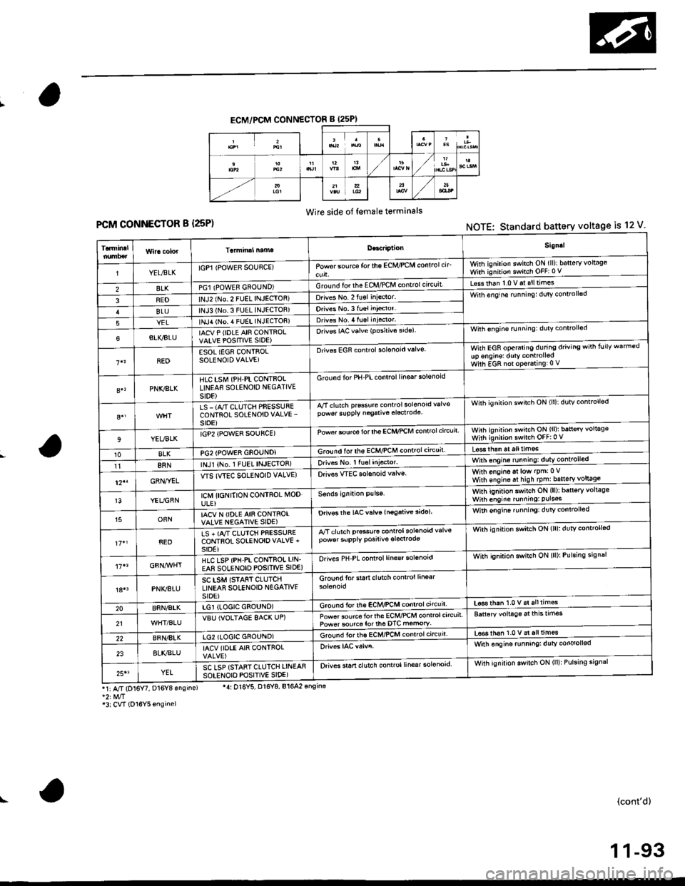
ECM/PCM CONNECTOR B (25PI
Wire side of female terminals
FCM CONNECTOR B {25P)NOTE: Standard battery voltage is 12 V
Sign.l
YELtsLKIGP1 IPOWER SOUflCE)Powor sou rca for the ECM/PCM conlrolcirwhh ignilion swilch ON (ll)ibatteryvoltageWith ignition switch OFF:0 V
BLKPGl {POWEB GNOUND)Ground fo. the ECM,/PCM contrclcncuit'Less than 1.0 V at slltimes
FEDlNJ2 (No 2 FUEL INJECIOR)Drives No. 2 fu€l inieclor'Wirh enqine runnin9: dulv conlroll6d
BLUlNJ3 (No.3 FUEL INJECTOB)Orives No.3 fuel inieclor'
YELlNJ,r lNo. 4 FUEL INJECTOF)Drives No. 4 luel injector'
6BLI(BIUIACV P (IDLE AIR CONTROLVAIVE POSITIVE SIDE)O.iv€s IAC valve {Posirivo side)Wilh engine running: duty conrrollod
BEDESOL {EG8 CONTROLSOLENOID VALVE)Drives EGF controlsolonoid valveWith EGR operaiing during driving wirh follv warmedup onginsl dutY controlledWilh EGR nol op€r.ring:0 V
PNKSLKHlC tstvr (PH-PL CONTnOLLINEAfl SOLENOID NEGATIVEst0E)
G rcund for PH-PL control linsar solsnoid
8.,LS - (A/T CLUTCH PFESSURECONTROL SOTENOIDVALVE'sroE)
A/Tclutch prsssure conrrol sol€nod valv€pow6r slpply negative elecrodeWith ignilion swirch ON (ll):dutv controll€d
9YEUBLKrGP2 {POWE8 SOUFCE)Powor $urce for lhe ECI{,'PCM controlc'rcuitwnh ignirion swirch ON (ll): ban€ry voltag€with ignirion swnch oFF:0 v
10BLKPG2IPOWER GSOUNDIGround lor ths ECM/PCM controlctrcuil
118RNINJl {No,1 FUEL INJEqIOR)orives No. r ru6l Iniocror.With onsino at low lpm:0Vwith ens,n. ar hish tpm:bsneryl9!9gl-12"GRN,.YELWS (WEC SOLENOID VALVE)Orivos WEC solanoid v.lvs.
13YEUGRNICM {I6NITION CONTROL MODULE}
With ignition switch ON (ll)r b5n6ry volt€gsWilh engino running: Puls6
15ORNIACV N (IDLE AIN CONTSOIVALVE NEGATIVE SIOE)Drivos the IAC valve lnogativ€ 3idelWith €ngin€ ru nningi dr]tv controlled
REDLS + (A,/T CIUICH PRESSURECONTFOT SOIENOIOVALVE +SIDE}
A/T clutch pr€so.6 controlsolenoid valvepow6r slpply posiliv€ oroclrodeWirh ignition swatch ON (lll: dutYcontrorled
HLC LSP (PH-PI CONTROI LIN.EA8 SOLENOID POSITIVE SIDE)Orives PH-PL control line€r solenoidWith qnition switch ON (lll: Pulsing srgnal
PNK/BTUSC LSM (STAfiT CLUTCHLINEAR SOLENOIO N€GATIVESIDE)
Groundforstartclutchcontrol line6r
20BnN/AtKLGI (LOGIC GEOUNO)Ground for lh€ EcM/PcM controlcircuit'L6se rhan 1.0 v.i alltimes
21VBU IVOLTAGE 8AC( UP)Powet source torlhe ECM/PCM control circuitPower sourco tor th6 DTC m€mory'Battaryvoltage aitnEtrmes
22BFN/8IKLG2 (LOGIC GSOUND)Ground iorths ECMnCM conrrol circuir'tsss thah 1.0 v al all times
238LI(BLUIACV (IOTE AIR CONTROLWitn ongine funning: dutv conrol!6d
25'3YELSC LSP {STANT CLUTCH LINEARsotENorD PoSlrlvE slDE)Orives sran clutch control linesr solonoid.With ignilion swilch ON (ll): Pulsing sign3r
r1: A/r (D16 , D16Y8 ensins)
'3:CVT {O16Y5ensino)
'4: Ol6Y5, Dl6Y8, B164? onsina
(cont'd)
1 1-93
Page 363 of 2189
Troubleshooting
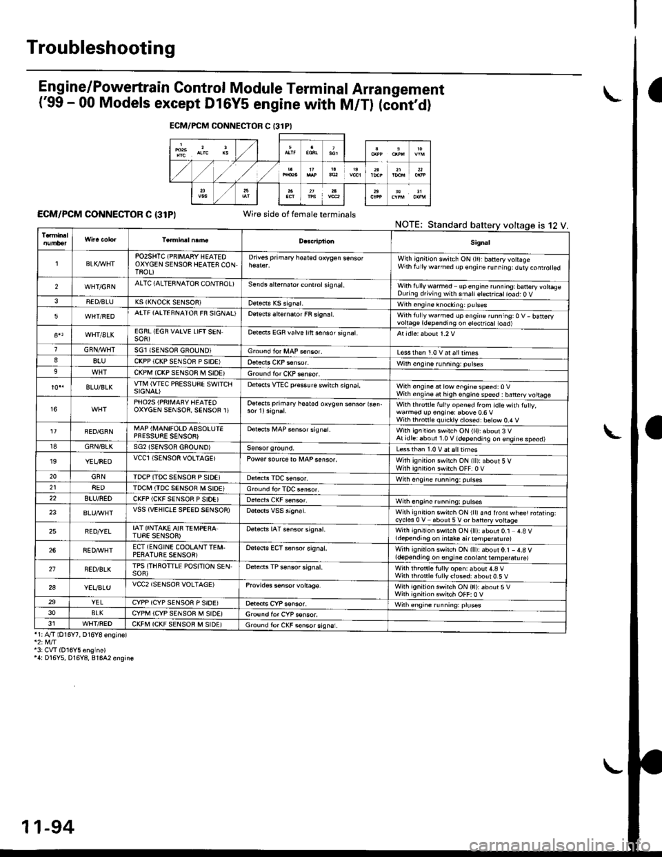
Eng ine/P_owertrain Control Module Term inal Arrangement
('99 - 00 Models except Dl6Y5 engine with M/Tl (cont,d)
ECM/PCM CONNECTOR C {31P)Wire side of female terminalsNOTE;Standard
*1;4"/T lD16Y7, D16Y8 ensinel
43: CVI(016Y5 engine)'4: D16Y5, D16Y8, 81642 engin€
ECM/FCM CONNECTOR C 13lPI
is 12 V.
Sig.al
lBLK4/VHTPO2SHTC (PNIMARY HEATEOOXYGEN SENSOB HEATES CONTROL)
Drivss primary hoated orygen sensofWith ignition switch ON (lr)rbanery volageWrh fJly warned up €ngir. ru..i19: duty.oaro ed
2WHT/GFNALTC (ALTESNATOB CONTSOL)Sends aliernalo. control sig nal,With fullywa.med upengine ronning; banery vohaseDuring d.iving with smallelect.icatioad; O V38ED/BLUK5 (KNOCK SENSOR)with sngine knocking: pulses
5WHT/REDATTF {AITEFNATOR FR SIGNAL'Detects slternaror FR si9n.l.With tullywarmed up engine running:O V- batteryvortage(dependingon erectficat toad)
WHT/8LKEGRL (EGN VAIVE LIFTSENSOR)Dete.ts EGR valve lrft sensorsignat.
GRN,4r'l/flTSGl ISENSOE GBOUND)Groond fo. MAP s€nsor.L€ss rhan 1.0 v at alltimes88luCKPP (CKP SENSOR P SIOE'With engine running: pulses9CKPM {CKP SENSOR M SIDEIGround for CKP sensor.
BLU/BLKwlvl (wEc PREssuSE swtTcllSIGNAI)D€tocts VTEC pfessure switch signat,With €ngine at low enginospeed:0VWith engin€ at high engino speed : banery vo ttaae
16PHO25 (PRII\,1AFY HEATEDOXYGEN SENSOR, SENSOR 1)Oetects primary heated oxygen s6nsor lsen-With lhrottle f!l1y open€d from idtewith tuly,wa.med !p engin€: Ebove 0.6 VWilh thronl€ quickly closed: b€tow 0.4 V
FED/GRNMAP (I\,4ANIFOLD ASSOLUIEPFESSUSE SENSOB}Dotocrs i,4AP sensor signsl.With ignitioh switch ON (ll):about 3 VAt idlei6boul 1.0 V (depending on engine speed)18GBN/8LKSG2 (SENSOR GSOUND)Less than 1.0 V aralttimes'19YEUNEDVCCl (SENSOR VOLTAGEIPowersourcero MAPsenso..With ignition swilch ON {ll):about 5 VWirh iqnition switch OFF]0 V20GNNIDCP (TDC SENSOB P SIDEIWith ongine running: pulses218EDTDCI\,I (TDC SENSOR M SIOE)Ground lor TOC aensor.22BTU/NEDCKFP (CKF SENSOR P SIDE)With engine running: p!lses
23VSS {VEHIClE SPEED SENSOR)Wilh ignrt|on swich ON rllr snd lront wl-ee' rotating.cycles 0 V about 5V or baneryvottage
25BED/YELIAT ONTAKE AIF TEi,4PEBA.TUEE SENSOR)Detects IAT senso. signat.With ignition switch ON (ll): about 0.1 4.8 Vldepending on i.take air ternpe.atu re)
268ED,ryVHTECT (ENGINE COOLANTTEI\,I.PESATUBE SENSOR)Oelects ECT sensor signal.With ignirion swirch ON {ll):about0.1 -4.8 V(depending on engine coolant temperatu re)
21NED/BLKTPS (THROTTLE POSITION SEN,SOF)Detects TP sensor signal.Wilh th.onle fully op€n: about 4.a VWith rhronle f!lly closed: about 0.5 V
2aYEVBLUVCC2 (SENSOR VOLTAGE)Provides s6nsor voltag€.With ignirion swirch ON (tt):about 5VWith ignilion swiich OFF:0 V29YELCYPP (CYP SENSOR P SIDE)Wilh €ngrne running: pruses3oBLKCYPM (CYP SENSOR M SIDE]G,ound for CYP sonsor.J1WHT/FEDCKFM (CKF SENSOB M SIDE)Ground fo. CKF sonsorsign6i.
11-94
Page 365 of 2189
Troubleshooting
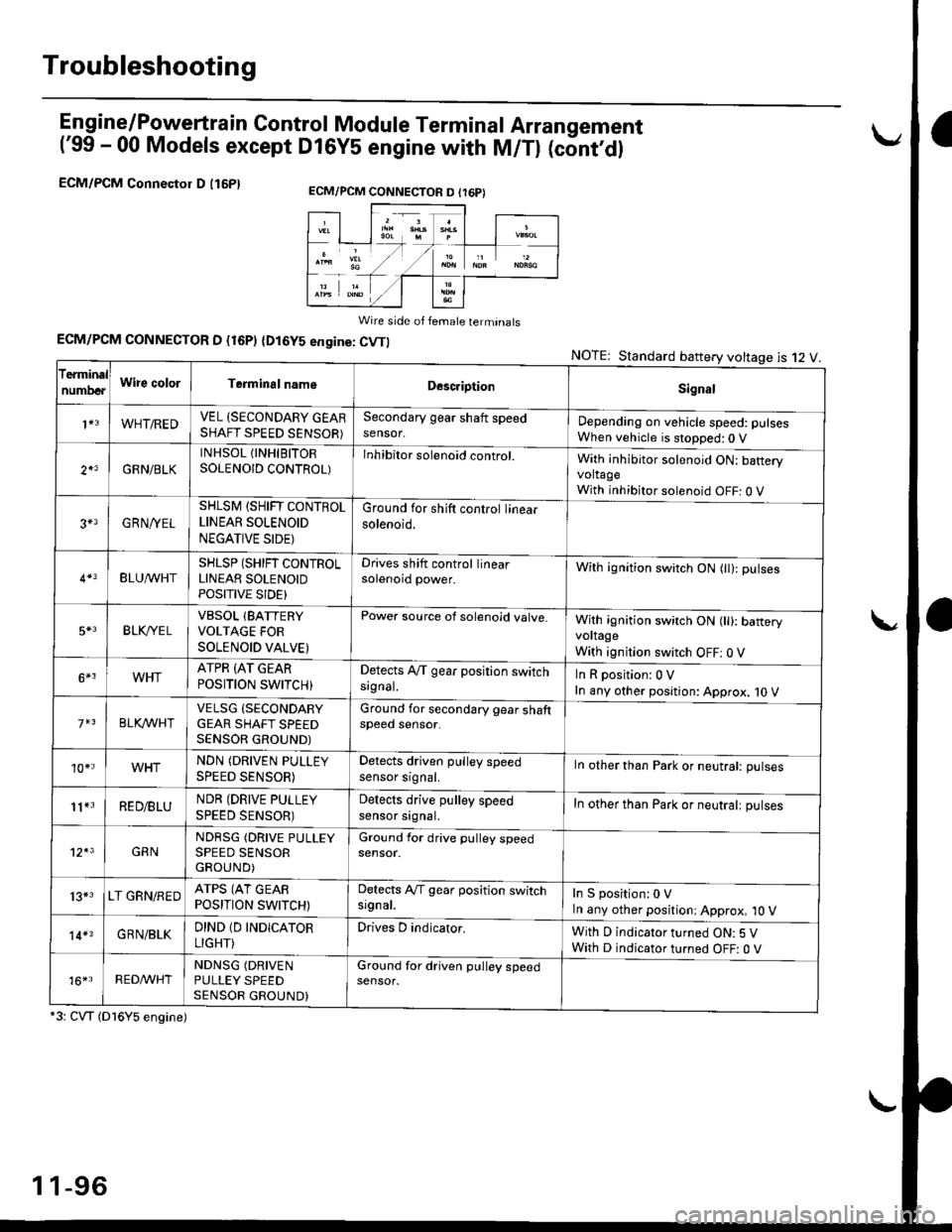
En gine/P_oweft ra in Control Module Termina I Arran gement
('99 - 00 Models except Dl6YS engine with M/Tl (cont,dl
ECM/PCM Connectol D (16P1
Wire side of female terminats
ECM/PCM CONNECTOR D {16P) (Dl6YS engine: CVTI
*3: CVT (Dl6Y5 engine)
NOTE: Standard battery voltage is 12 V
ECM/PCM CONNECTON D (r6P)
f€rminal
numDeaWire colorTerminalnameDescriptionSignal
1+3WHT/REDVEL (SECONDARY GEARSHAFT SPEED SENSOR)
Secondary gear shaft speedsensor,Depending on vehicle speed: pulsesWhen vehicle is stopped:0 V
2*3GRN/BLK
INHSOL {INHIBITORSOLENOID CONTROL)Inhibitor solenoid control.With inhibitor solenoid ON: bafteryvoltageWith inhibitor solenoid OFF: 0 V
3+3GRN/YEL
SHLSM (SHIFT CONTROLLINEAR SOLENOID
NEGATIVE SIDE)
Ground for shift control linearsolenoid.
BLU^/vHTSHLSP (SHIFT CONTROLLINEAR SOLENOIDPOSITIVE SIDE}
Drives shift control linearsolenoid power.With ignition switch ON (tl): pulses
5*3BLK,/YE LVBSOL lBATTERYVOLTAGE FOR
SOLENOID VALVE)
Power source of solenoid valve.With ignition switch ON (ll): baneryvoltage
With ignition switch OFF: 0 V
6*3WHTATPR (AT GEAR
POSITION SWITCH)Detects A,/T gear position switchsrgnal.InRposition:0V
In any other position: Approx. 10 V
BLKA/VHIVELSG (SECONDARY
GEAR SHAFT SPEEDSENSOR GROUND)
Ground for secondary gear shaftspeed sensor.
10*.WHTNDN (DRIVEN PULLEY
SPEED SENSOR)
Detects driven pulley speedsensor srgnal.In other than Park or neutral: pulses
11*3RED/BLUNDR (DRIVE PULLEY
SPEED SENSOR)
Detects drive pulley speedsensor srgnal.In other than Park or neutralt pulses
12*3GRNNDRSG (DRIVE PULLEYSPEED SENSORGROUND)
Ground for drive pulley speedsensor.
13*3LT GRN/REDATPS (AT GEARPOSITION SWITCH)
Detects Ay'T gear position switchsrgnal.In S position:0 VIn any other positioni Approx, 10 V
14*3GRN/BLKDIND 1D INDICATOR
LIGHT)
Drives D indicator.With D indicator turned ON: 5 VWith D indicator turned OFF: O V
16*rRED^/VHTNDNSG (DRIVEN
PULLEY SPEEDSENSOR GROUND)
Ground for driven pulley speedsensor.
1 1-96
Page 371 of 2189
Troubleshooting
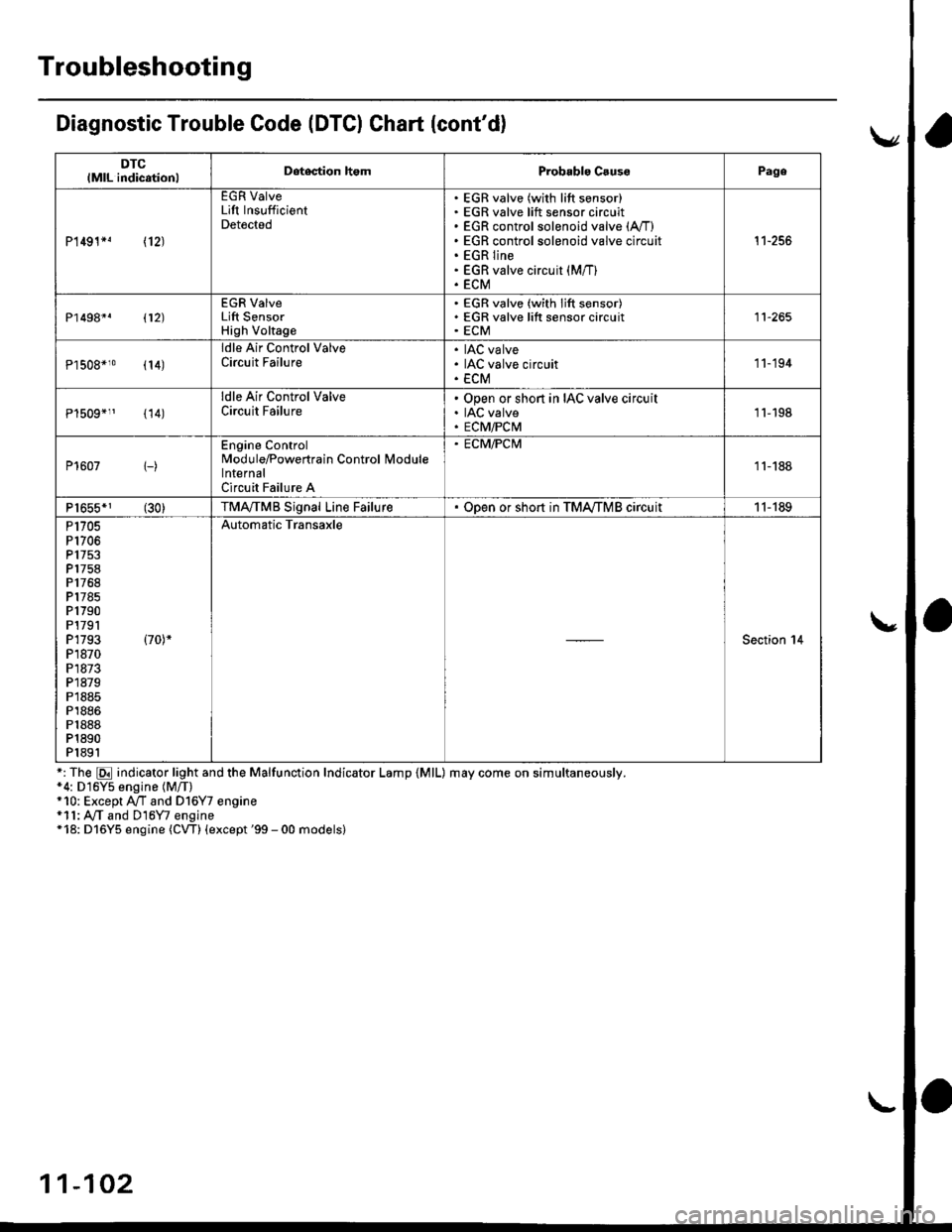
Diagnostic Trouble Code (DTCI Ghart (cont'd)
DTClMlL indicationlDetegtion homProbablo CsussPage
P1491*! \12J
EGR ValveLift InsufficientDetected
EGR valve (with lift sensor)EGR valve lift sensor circuitEGR control solenoid valve (A,/I)
EGR control solenoid valve circuitEGR lineEGR valve circuit (M/T)
ECM
't1-256
P1498*. 112)
EGR ValveLift SensorHigh Voltage
EGR valve (with lift sensor)EGR valve lift sensor circuitECM11-265
Pl508*10 (14)
ldle Air Control ValveCircuit FailureIAC valveIAC valve circuitECM
'11-194
{14)
ldle Air Control ValveCircuit FailureOpen or short in IAC valve circuitIAC valveECM/PCM1l-198
P1607 1-)
Engine ControlModule/Powertrain Control lvlodulelnternalCircuit Failure A
. ECM/PCM
11-188
P1655*1 (30)TMA,/TMB Signal Line FailureODen or sho.t in TMA,/TMB circuit11-189
P1705P1706P 1753P1758P1768P1785P1790P1791P1793 (70)*
P1870P1873P1879P1885P1886P1888P1890P1891
Automatic Transaxle
Section 14
*: The E indicator light and the Malfunction Indicator Lamp {MlL) may come on simultaneously.*4: D16Y5 engine (M/T)+10: Except A/T and Dl6Y7 engine*11: A,/T and D16Y7 engine*18: D16Y5 engine (CW) (except '99 - 00 models)
11-102
Page 372 of 2189

How to Read Flowcharts
A flowchart is designed to be used from start to final repair. lt's like a map showing you the shortest distance. But beware:
lf you go off the "map" anywhere but a "stop" symbol, you can easily get lost.
tSrARTl(bold type)
FanoNl
@
tsroP I
{bold type)
Describes the conditions or situation to start a troubleshooting flowchart.
Asks you to do something; perform a test, set up a condition etc.
Asks you about the result of an action, then sends you in the appropriate troubleshooting direction.
The end of a series of actions and decisions. describes a final repair action and sometimes directs you to
an earlier part of the flowchart to confirm your repair,
NOTE:
. The term "lntermittent Failure" is used in these charts, lt simply means a system may have had a failure. but it checks
out OK at this time. lf the Malfunction Indicator Lamp (MlL) on the dash does not come on, check for poor connections
or loose wires at all connectors related to the circuit that you are troubleshooting (see illustration below)'
. Most of the troubleshooting flowcharts have you reset the Engine Control Moduls (ECM)/Powertrain Control Module
(pCM) and try to duplicate the Diagnostic Trouble Code (DTC). lf the problem is intermittent and you can't duplicate the
code, do not continue though the flowchart. To do so will only result in confusion and, possibly, a needlessly replaced
ECM/PCM.
. ,,Open" and "Short" are common electrical terms. An open is a break in a wire or at a connection. A short is an acci-
dental connection of a wire to ground or to another wire. In simple electronics, this usually means something won't
work at all. In complex electronics (like ECM's/PCM'sl. this can sometim€s mean something works, but not the way it's
suDDosed to.
toosE
1 1-103
Page 373 of 2189

PGM-FI System
System Description
CKP/TDC/CYP Sensor
MAP Sensor
IAT SensorTP SensorEGR Valve Lift Sensor*'Primary H02SSecondary HO2SVSSBARO SensorELD*'KS€Starter SignalALT FR SignalAir Conditioning SignalA/T Gear Position SignalBattery Voltage {lGN.1}Erake Switch SignalPSP Switch SignalFuel Tank Pressure Sensor*iVTEC Pressure Switch*5Clutch Switch Signal*6Countershaft Speed SensornBMainshaft Speed Sensorrs
-\
----t /
F;ilrr j"-----fi-tri-'r.;l
Fb"t."'i" d" c;;il
F,h"'c;;tr*".io";-l
@."r.l"sc;;ll
EaM/PcM B""k-p F"""till
r\
-:/
Fuel IniectorsPGM-Fl Main Belay {Fuel Pump)MILIAC Valve!y'C Compressor Clutch RelayRadiator Fan Relay*,Condenser Fan RelayALT*'lcMEVAP Purge Control Solenoid
Primary HO2S HeaterSecondary H02S HeaterEGR Control Solenoid Valve*rEGR valve*6EVAP Bypass Solenoid Valve*'EVAP Control Canister Vent Shut
VTEC Solenoid Valve*5DLCLock-up Control Solenoid Valve*aShift Control Solenoid Valve*3Linear Solenoid Valve*3
*1: Dl6Y5 engine*2: USA model*3: CW (D16Y5 ensine), D16Y8 engine and 81642 ensine*4: '96 D16Y8 engine lcoupe),'97 Dl6Y7 engine (coupe: KL model, sedan: KL (LX) model),'97 D16Y8 engine {coupe: all models, sedan: KLmodel),'98-all models,'99'all models,'00-all models+5: D16Y5, D16Y8,816A2 engine*6: M/T (D16Y5 enginei*7: CVT 1D'l6Y5 engine)+8: A/T (D16Y7, D16Y8 engine)*9: '96 D16Y5 engine,'96 D16Y7 engine,'96 Dl6Y8 engine (sedan),'97 D16Y5 engine,'97 Dl6Y7 engine (coupe: KA, KC models, sedan:KA, KC, KL (LX) models, hatchback: all models),'97 D16Y8 engine (sedan: KA, KC modelsi
PGM-FI Sy3lem
The PGM-Fl system on this model is a sequential multipon fuel injection system.
Fuel iniector Timing and Duration
The ECM/PCM contains memories for the basic discharge durations at various engine speeds and manifold air flow rates.
The basic discharge duration, after being read out from the memory. is further modified by signals sent from various sen-
sors to obtain the final discharge duration.
ldle Air Control
ldle Air Control Valve llAC Valve)
When the engine is cold. the A,/C compressor is on, the transmission is in gear, the brake pedal is depressed, the P/S load
is high, or the alternator is charging, the ECM/PCM controls current to the IAC Valve to maintain the correct idle speed.
lgnition Timing Control
. The ECM/PCM contains memories for basic ignition timing at various engine speeds and manifold air flow rates.
lgnition timing is also adjusted for engine coolant temperature.
. Aknockcontrol system was adopted which sets the ideal ignition timing for the octane rating ofthegasoline used.*3
Othgr Control Funqtions
1. Starting Control
When the engine is started, the ECM/PCM provides a rich mixture by increasing fuel injector duration.
2. Fuel Pump Control
. When the ignition switch is initially turned on, the ECM/PCM supplies ground to the PGM-Fl main relay that sup-plies current to the fuel pump for two seconds to pressurize the fuel system.. When the engine is running, the ECI\4PCM supplies ground to the PGM-FI majn relay that supplies current to the fuel
oumo.
. When the engine is not running and the ignition is on, the ECM/PCM cuts ground to the PGM-FI main relay which
cuts current to the fuel pump.
11-104
INPUTS
ENGINE CONTROL MODULE (ECMY
POWERTRAIN CONTROL MODULE (PCM) OUTPUTS
Page 376 of 2189

I
Engine Control Module/Powertrain Control Module (ECM/PCM)
t'96 - 98 Models,'99 - 00 Dl6Y5 engine with M/Tl
L
NOTE: lf th is svmptom is intermittent, check for a loose fuse No. 25 {METER 7.5 A) in the
underdash {use/relay box, a poor connection at ECM/PCM terminal A18, or an intermit
tent ooen in the GRN/ORN wire between the ECM/PCM (A18) and the gauge assemblv.
ECM/PCM CONNECTOR A I32PIPGl {BLKI
Wire side ot female terminals
ECM/PCM CONNECTOR A (32P}
Wire side of female terminals
(cont'd)
11-107
The Malfunc{ion Indicator Lamp
{MlLl never comes on (even lor
two secondsl atter ignition is
turned on.
Turn the ignition switch ON (ll).
- Repair short or open in thewile botwoen No. 25 {M€TERI
17,5 Altus€ and gau99 assem'
bty.- Replaco No.25 IMETERI (7,5
A)tuse.
ls the low oil pressure light on?
Try to start the engine.
Does the engine stan?
Check lor an open in the wiles
{PG linosl:1. Turn the ignition switch ON (ll).
2. ldeasure vo ltage betweenbody ground and ECM/PCMconnector terminals A10 andA23 individually.
Check tor an open in the wire ot
bulb (MlL line):1. Turn the ignition switch OFF.
2. Connect the ECM/PCM con-nector terminal A'18 to bodyground with a jumper wire.3. Turn the ignition switch ON (ll).
Repair open in the wire(s)
between ECM/PCM and G101(localod at the thetmostat hous_ingl that had more than 1.0 V.
ls thore less than 1.0 V?
Substituto . known-good ECM/PCM and recheck. It symptom/indication go6s away, roPlace
the origin.l ECM/PCM.
- Repair open in th€ wiresbetwoen ECM/PCM lAl8l andgaug6 a$embly.- Replace the MIL bulb,
ls the MIL on?
Substitute a known-good ECM/
PCM and .echeck. lf symptom/indication goes away, replacothe origin.l ECM/PCM.
268l011
12l3t5t61tIt192022232a
2527xt30
MrL I luanpen wrnrIGRN/ORN) I
!1,