Page 366 of 2189

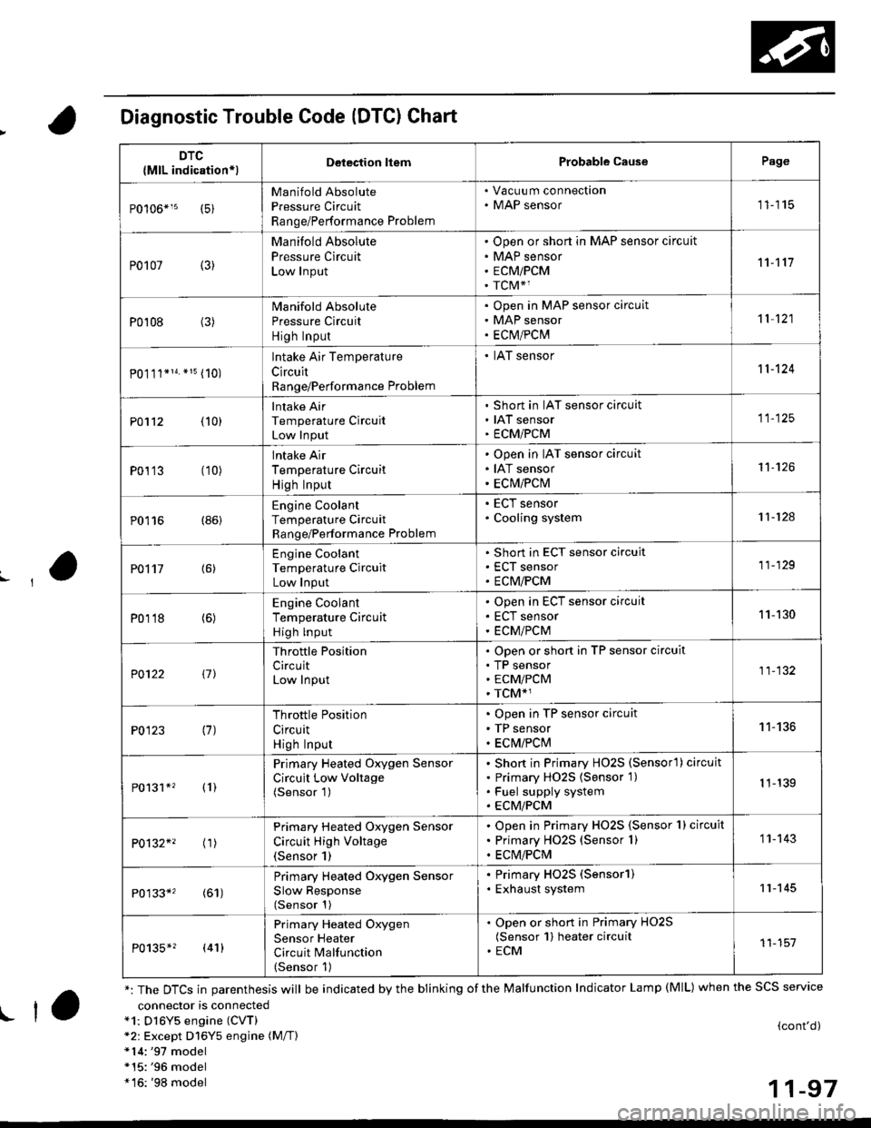
Diagnostic Trouble Code (DTCI Chart
connector is connecteda1: Dl6Y5 engine (CVT)*2: Except D16Y5 engine (M/T)*14:'97 model*15:'96 model*16: '98 model
(cont'd)
11-97
DTC
{MlL indication*lDelection liemProbable CausePage
Manifold Absolute
Pressure Circuit
Range/Performance Problem
. Vacuu m connection. MAP sensor11115
P0107 (3)
Manifold Absolute
Pressure Circuit
Low Input
Open or short in MAP sensor circuit
MAP sensor
ECMiPCM
TCM*1
11't1'l
P0108 (3)Manifold Absolute
Pressure Circuit
High Input
Open in MAP sensor circuit
MAP sensor
ECtvt/PCM
't 1 121
P0.111*14. *15 (10)
lntake Air Temperature
Circuit
Range/Performance Problem
. IAT sensor11-124
PO112 {10}
Intake Air
Temperature Circuit
Low Input
Short in IAT sensor circuit
IAT sensor
ECMiPCM
11-125
P0113 (10)lntake Air
Temperature Circuit
High Input
Open in IAT sensor circuit
IAT sensor
ECM/PCM
't1-126
P0116 (86)Engine Coolant
Temperature Circuit
Range/Performance Problem
. ECT sensor. Cooling system11-124
PO't't7 {6)
Engine Coolant
Temperature Circuit
Low Input
Short in ECT sensor circuit
ECT sensor
ECM/PCM
11-129
P0118 (6)Engine Coolant
Temperature Circuit
High lnput
Open in ECT sensor circuit
ECT sensor
ECM/PCM
11-130
?0122 t1l
Throttle Position
CircuitLow Input
Open or short in TP sensor circuit
TP sensorECM/PCM
TCM*1
11-132
P0123 (7)Throttle Position
Circuit
High Input
Open in TP sensor circuit
TP sensor
ECM/PClvl
11-136
P0131*' (1)
Primary Heated Oxygen Sensor
Circuit Low Voltage(Sensor 1)
Short in Primary HO2S (Sensorl ) circuit
Primary HO2S {Sensor 1)
Fuel supply system
ECM/PCM
1 1-139
P0132*' ('�r)
Primary Heated Oxygen Sensor
Circuit High Voltage(Sensor 1)
Open in Primary HO2S {Sensor 1} circuit
Primary HO2S (Sensor 1)
ECM/PCM
1 1- 143
P0133*' (61)
Primary Heated Oxygen Sensor
Slow Response(Sensor 1)
. Primary HO2S (Sensorl). Exhaust system11-145
P0135*? (41)
Primary Heated Oxygen
Sensor Heater
Circuit Malfunction(Sensor 1)
. Open or short in Primary HO2S(Sensor 1) heater circuit. ECM11-151
*: The DTCS in parenthesis will be indicated by the blinking of the Malfunction Indicator Lamp (MlL) when the SCS service
! ta
Page 434 of 2189

t
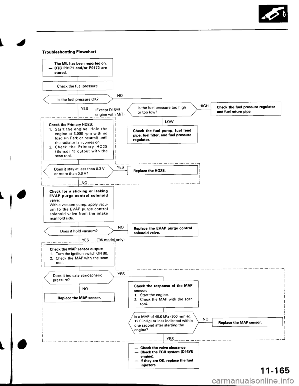
Troubleshooting Flowchart
'l
NO
a-,-:- -
YES
- The MIL ha3 b€on rePorled on.- DTC P0171 a^dlot P0172 arc
stored,
is the fuel pressure OK?
Check the fuel pt€ssure regulator
and fusl re{urn pipe.ls the fuel pressure too high
ortoo low?
Check the Primary HO2S:
1. Start the engine. Hold the
engine at 3,000 rpm with no
Ioad (in Park or neutral) until
the radiator Ian comes on
2. Check the Primary HO2S(Sensor 1) output with the
scan tool,
Check the tu6l pump. fuel leedpipe, fu€l fiher, and Iuel Pressureregulator.
Does it stay at less than 0.3 V
or more than 0.6 V?
Check lor a sticking or leaking
EVAP purge control solenoid
With a vacuum PumP, aPPIY vacu-
um to the EVAP purge control
solenoid valve from the intake
manifold side.
Does it hold vacuum?
Check the MAP sensor outputr
1. Turn the ignition switch ON (ll)
2. Check the MAP with the scan
tool.
Check th6 response of the MAP
sensoa:1. Start the engine.2. Check the MAP with the scan
tool.
ls a MAP of 40.0 kPa 1300 mmHg,12.0 inHg) or less indicated within
one second after starting the
engine?
- Check th€ valve cloarance.- Check the EGR rystem lD16Y5enginel.- lf they are OK, r€place the tueliniocto]3.
1 1-165
Page 459 of 2189
ldle Control System
System Description
The idle speed ot the engine is controlled by the ldle Air Control (lAC) Valve.The valve changes the amount of air bypassing into the intake manifold in response to electric current controlled bv theECM/PCM. When the IAC Valve is activated, the valve opens lo maintain the proper idle speed.
D16Y5, D16Y8, Br6A2 engine (M/T):
(ROTARYItac vat-vEEI{GINEcooLAI{T
VARIOUSsEI{SORS
VARIOUSSENSORS
INTAKE MANIFOTDDl6Ys {CVTl, D16Y8 engine lA/T):
D16Y7 engine:
{ROTABY)
;iy--, - ---
INTAKEMANIFOLD
11-190
Page 461 of 2189

ldle Control System
ldle ControlSystem
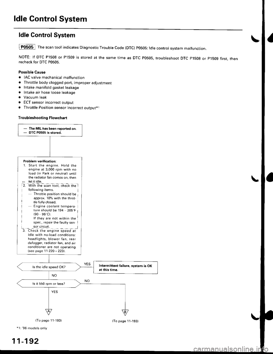
lF0505 l Th" """n tool indicates Diagnostic Trouble Code (DTC) PO5O5: tdte controt system malfunction.
NOTE: lf DTC P1508 or P1509 is stored at the same time as DTC P0505, troubleshoot DTC p1508 or p1bog first. thenrecheck for DTC P0505.
Possible Cause
. IAC valve mechanical malfunction
. Throttle body clogged pon, improper adjustment. Intake manifold gasket leakage
. Intake air hose loose leakage
. Vacu um leak
. ECT sensor incorrect output
. Throttle Position sensor incorrect output*r
Troubleshooting Flowchart
The MIL has been reoorted on.DTC P0505 is stored.
Problem verification:1. Start the engine. Hold theeng;ne at 3,000 rpm with noload (jn Park or neutral) untilthe radiator fan comes on, then*r let it idle.t2. with rhe scan toot, ct'eit Ge l
Throttle position should beapprox. 10% with the throttle fully closed.E ngine coolant tempera-ture should be 194 205'F(90 96.Ci.lf they are not within thespec., repair the faulty sen
L._ _9oI9[cr]41 l3. Chec& the engine speed atidle with no-load cond;tionsiheadlights, blower fan, reardefogger, radiator fan, and airconditioner are not operating\see page l1-22O - 223).
Intermittent tailure, system is OKat this time.ls the idle speed OK?
ls it 550 rpm or less?
(To page 11,193)
*1r'96 models only
11-192
(To page ll-193)
Page 501 of 2189
Fuel Supply System
Fuel Injectors
Replacement
@ Do not smoke when working on the tuel systgm, Keep gp6n flames away from your work area
'f. Relieve the fuel pressure (see pages 11-230,231J.
2. Disconnect the connectors from thefuel injectors (D16Y7 engine: Remove the air cleaner).
3. Disconnect the vacuum hoses from thefuel pressure regulator. Placeashoptowel overthefuel return hose, then dis-connect it from the fuel pressure regulator. Disconnect the vacuum hoses and 2P connector from the EVAp purgecontrol solenoid valve.
4. Remove the retainer nuts on the fuel rail.
5. Disconnect the fuel rail.
6. Removethefuel injectors from the intake manifold.
D16Y5, D16Y8 engine:
NOTE: lllustration shows D16Y8 engine.
D16Y5 engine is similar.
12 N.m11.2 kgl.m,8.7 rbt.ft)
12 N.m11.2 lgl.m,8.7 rbt.ftl
.q
wE4
Y
Ve
ffi}Yg
E
O.RINGReplace.
CUSHIONRINGReplace.
O.RINGReplace.
cusl{toNRINGReplace.
SEALRINGReplace.
ffi
E
EV
R
w
t
YEVAPPURGE CONTNOLSOLENOID VALVE
FUEL
11-232
Page 502 of 2189

\J
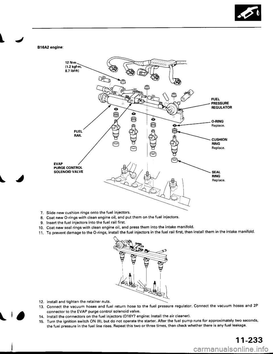
81642 engine:
EVAP
12 N.m
{1.2 kgl m;8.? lbt.ft)
FUELPRESSUREREGULATOR
O.RINGReplace.
cusHloNRINGReplace.
PURGE CONTROLSOLENOID VALVE
\
SEALRINGReplace.
7. Slide new cushion rings onto the fuel injectors.
8. Coat newO-ringswith clean engineoil, and putthem onthefuel injectors.
9. Insert the fuel injectors into the fuel rail first.
10. Coatnewseal rings with clean engine oil,and press them intothe intake manifold.
11. To prevent damage to the O-rings, installthe fuel injectors inthefuel rail first, then install them inthe intake manifold.
'12. Install and tighten the retainer nuts.
13. Connect the vacuum hoses and fuel return hose to the fuel pressure regulator, Connect the vacuum hoses and 2P
connector to the EVAP purge control solenoid valve.
14. Install the connectors on the fuel inl'ectors (D16YI engine; Install the air cleaner).
15. Turn the ignition switch ON (ll), butdo not operate the starter. After the tuel pump runs for approximately two seconds,
the fuel pressure in the fuel line rises. Repeat this two or three times, then check whether there is any fuel leakage.
11-233
Page 512 of 2189
Intake Air System
\JSystem DescriPtion
The system supp|ies air for a|| engine needs' |t consists of the intake air pipe' Air C|eaner (ACL}, intake air duct, Thrott|e
Body (TB), ldle Air control (lAc) valve and intake manifold. A resonator in the intake air pipe provides additional silencing
as air is drawn into the system.
D16Y5, D16Y8, 816A2 engine {M/Tl
YEL/ - From PGM-FIaLK - MA|N RELAY
BLK/BLU
-- ORN
INTAKEAIRDUCT
IROTARYIIAC VALVE
Iaru
ENGINECOOLANT
BLK/
INTAKEAIR DUCT
I
D16Y5 engine (CVT), D16Y8 engine (A/T)' f'ttlxr ,tla"tpoto
D16Y7 engine:
{ROTARY)IAC VALVE
VARIOUSSENSORS
INTAKEAIRPIPE
tr
RESONATOR
!r,
IAC VALVE
BLK
11-243
Page 523 of 2189
Emission Control System
Exhaust Gas Recirculation (EGR) System (D16yS engine)
Doscription
The EGR system is designed to reduce oxides of nitrogen emissions (NOx) by recirculating exhaust gas through the EGRvalve and the intake manifold into the combustion chambers. lt is composed of the EGR valve. EGR vacuum conrrot vatve.EGR control solenoid valve. ECM and various sensors.The EcM contains memories for ideal EGR valve lifts for varying operating conditions, The EGR valve lift sensor detectsthe amount of EGR valve lift and sends the information to the ECM. The ECM then compares it with the ideat EGR valve liftwhich is determined by signals sent from the other sensors. lf there is any difference between the two. the EcM cuts cur-rent to the EGR control solenoid valve to reduce vacuum applied to the EGR valve.
EGR CONTROLCVT: SOLENoID vALvE
EGN VALVE LIFT SENSOR
BLK
I
I
11-254