Page 1712 of 2189
Cruise Control
Gontrol Unit Input Test
SRS components are located in this area. Review the SRS component locations, precautions, and procedures in the SRSsection (24) before performing repairs or service.
1. Remove the driver's dashboard lower cover and knee bolster (see section 20).
2. Disconnect the l4P connector from the control unit.
3. Inspect the connector and socket terminals to be sure they are all making good contact.
lf the terminals are bent, loose, or corroded, repair them as necessary, and recheck the system.lf the terminals look OK, make the following inpul tests at the connecror.- lf any test indicates a problem, find and correct the cause, then recheck the system,- lf all the input tests prove OK, the control unit must be faulty; replace it.
14P CONNECTOR
CRUISE CONTROL UNIT
*i '99 00 models with A/T
23-242
GRN/WHT LT GRN/RED LT GRN/BI-K
8LU/GRN*
Wire side of female terminals
Page 1819 of 2189

How To Use This Manual
Circuit Schematics
oa
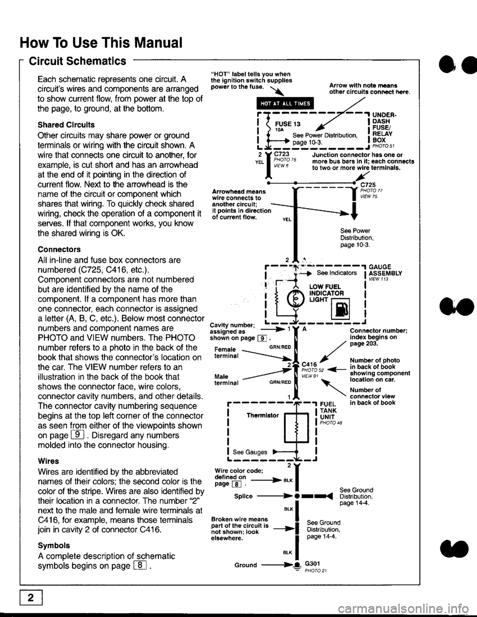
Each schematic represents one circult. A
circuit's wires and components are arranged
to show current flow, from power at the top of
the page, to ground, at the bottom.
Shared Circuits
Other circuits may share power or ground
terminals or wiring with the circuit shown. A
wire that connects one circuit to another, for
example, is cut short and has an arrowhead
at the end of it pointing in the direction of
current flow. Nelit to the anowhead is the
name o{ the circuil or comoonent which
shares that wiring. To quickly check shared
wiring, check the operation of a component it
serves. lf that component works, you know
the shared wiring is OK.
Connectors
All in-line and fuse box connectors are
numbered (C725, C416, etc.).
Component connectors are not numbered
but are identiJied by the name of the
component. lf a componenl has more than
one connector, each connector is assigned
a letter (A, B, C, etc.). Below most connector
numbers and comDonent names are
PHOTO and VIEW numbers. The PHOTO
number refers to a Dhoto in the back of the
book that shows lhe conneclor's location on
the car. The VIEW number refers to an
illustration in the back of the book that
shows the connector face, wire colors,
connector cavity numbers, and other details.
The connector cavity numbering sequence
begins at the top left corner oJ the connector
as seen from either of the viewooints shown
on page ffl . Disregard any numbers
molded into the connector housino.
Wires
Wires are identilied by the abbreviated
names of their colors; the second color rs the
color of the stripe. Wires are also identified by
their location in a connector. The number '2"
next to the male and female wire terminals at
C416, for example, means those terminals
join in cavity 2 of connector C416.
Symbols
A complete description of schematic
symbols begins on page | 8
"HOT" label tells you whenthe ignition switch suppliespower to the fuse. \
Artowhead meanswire connects toanother circuit;
Arrow with note rErngother circuils conncct h€re.
it .a
llu":: ^,{ ii t See Power Distribution, .I t----t oaqe tO-3. IL*--:--------J2 Y C723 Junction connectorYEL I Pao'o'8 more bus bars in it;
I - " " to two or more wire
l,/
-t>?
See PowerDistribution,page 10-3.
UNDER.DASHFUSE/RELAYBOX
has one oleach connactgterminala.
it ooints in directionof current flow.
TheImletor
t_I
Cavity number; L ---
Jiili'iJi!--' -----> '
shoin on page S .
Maleterminal
L?*?l?,-
"'"'I
c725
vlEUt/ 75
Connector number;index begins onpage 203.
Number ot photoin back ol bookshowing componentlocation on cat.
Number ofconneclor viewin back of book
7
GBN/FEO
See Ground
Soe Indicators I ASSEMBLY
:-------J
LOW FUELINDICATOFLIGHT r-l
EI
A
"o'r"/PHOTO 52 <-
\
FUELTANKUNIT
Splice ---------) O rr
".* I Page 14'4'
IBroken wire means | --^ -
iar";J.'It,;,rJ;ii; -----i Bffi,Bili*l
elsewhere. I 0a0e tn-a
IBrK Icround --->lL c301: ptioro 21
Page 1824 of 2189

Connector Views
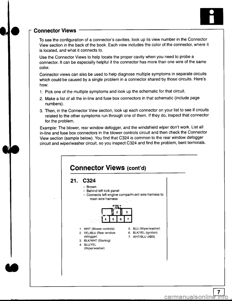
To see the configuration of a connector's cavities, look up its view number in the Connector
View section in the back of the book. Each view includes the color of the connector, where it
is located, and what it connects to.
Use the Connector Views to help locate the proper cavity when you need to probe a
connector. lt can be especially helpful if the connector has more than one wire of the same
cotor.
Connector views can also be used to help diagnose multiple symptoms in separate circuits
which could be caused by a single problem in a connector shared by those circuits. Here's
how:
1. Pick one of the multiple symptoms and look up the schematic for that circuit.
2. Make a list of all the in-line and fuse box connectors in that schematic (include page
numbers).
3. Then, in the Connector View section, look up each connector on your list to see il circuits
related to the other symptoms run through one of them. lf they do, inspect that connector
for the oroblem.
Example: The blower, rear window defogger, and the windshield wiper don't work. List all
in-line and fuse box connectors in the blower controls circuit and then check the Connector
View section (sample below). You find that C324 is common to the rear window defogger
circuit and wiper/washer circuit, so you inspect C324 and find the problem, bent terminals.
5.
6.
7.
1.
2.
WHT (Blower controls)
YEUBLU (Rear window
defogger)
BLK,ryVHT (Starting)
BLU/YEL(Wiper/washe0
8LU (Wiper/washed
BLfiEL (lgnition)
WHT/BLU (ABS)
Connector Views (cont'd)
21. C324
Brown
Behind left kick panel- Connects left engine compartry'ent wire harness to
main wire harness
ll,ll,
567
Page 1826 of 2189

Connectors - "C"
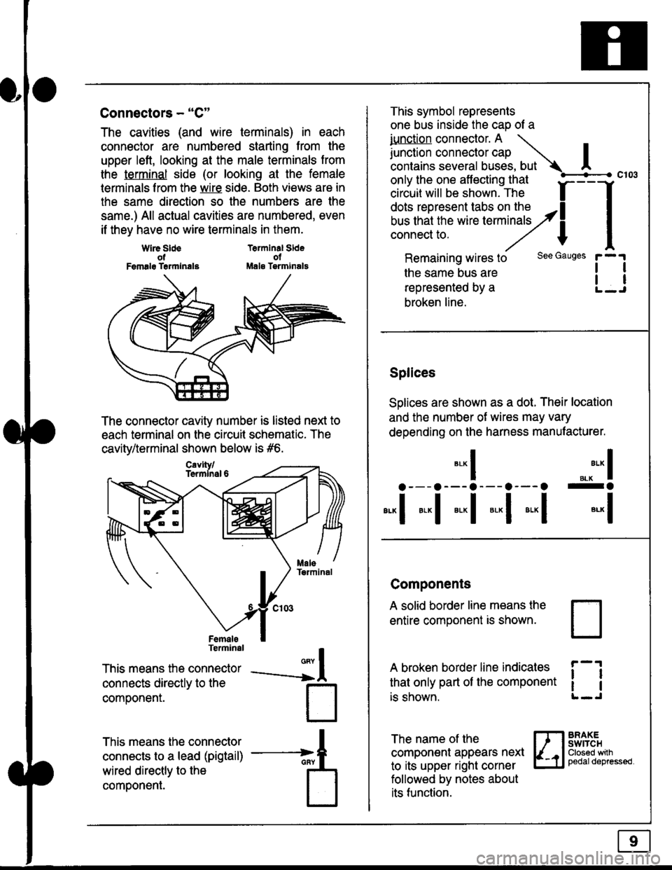
The cavities (and wire terminals) in each
connector are numbered starting from the
upper left, looking at the male terminals trom
the terminal side (or looking at the female
lerminals f rom the wire side. Both views are in
the same direction so the numbers are the
same.) All actual cavities are numbered, even
if they have no wire terminals in them.
Terminal SldeolMale Tsrminals
{
T
_A
Wlre SldeotFemalg Trrmlnala
The connector cavity number is listed next to
each terminal on the circuit schematic. The
cavity/terminal shown below is #6.
Terminal
This means the connector
connects directly to the
componenr.
This means the connector
connects to a lead (pigtail)
wired directly to the
component.
Cavlty/Termlnsl 6
only the one affecting that
ciriuit will be shown. The f
--f
!!*!"*F"#fi5'�;,Hy4
I
Remaining wires to
the same bus are
represented by a
broken line.
The name of the
component appears next
to its upper right corner
followed by notes about
its function.
This symbol represents
one bus inside the cao of a
iunction connector. A \
lr"ctb. connectorcap |contains several buses, but Ac103
tl
tl
*-
I ",.-"* I
a---a---a--- a--- o -a
*"1 *-l *-l *-l *"1 *-l
See Gauges
Splices
Solices are shown as a dot. Their location
and the number of wires may vary
depending on the harness manufacturer.
Components
A solid border line means the
entire component is shown.
A broken border line indicales
that only part of the component
is shown.
t_J
ll
ll
BRAXEswtTcHClosed wilhpedaldepressed.
Page 1834 of 2189
![HONDA CIVIC 1999 6.G Workshop Manual Fuse/Relay Information
- Under-dash Fuse/Relay Box
Front View
c712(To moonroof wire harness)
. : Canadai : Not UsedO : C926 loprion (+B)l
@ : C927 loption (dash lights)]
O : C928 [Option (ACC]I
@ : C9 HONDA CIVIC 1999 6.G Workshop Manual Fuse/Relay Information
- Under-dash Fuse/Relay Box
Front View
c712(To moonroof wire harness)
. : Canadai : Not UsedO : C926 loprion (+B)l
@ : C927 loption (dash lights)]
O : C928 [Option (ACC]I
@ : C9](/manual-img/13/6068/w960_6068-1833.png)
Fuse/Relay Information
- Under-dash Fuse/Relay Box
Front View
c712(To moonroof wire harness)
. : Canadai : Not UsedO : C926 loprion (+B)l
@ : C927 loption (dash lights)]
O : C928 [Option (ACC]I
@ : C929 loption (lc2)l
Rear View
css2
c421(To main wire harness)
c801CI-o SRS main harness)
c501(To dashboard wire harness)
^ : Not used ('96-'97 models)
c913(To ignition switch)
INTEGRATEDCONTROL UNITCONNECTOR A
c419Oo main wire harness)
REAR WINDOWDEFOGGER RELAY
TURN SIGNAUHAZARD RELAY
c423(To main wire harness)
co
c422(To main wire harness)
POWERwtNDowRELAY
c551flo lloor wire harness)c439 f96.'97 MODELSand ALL GX MOOELS)(To main wire harness)
T1 T-t T"l T"t r-r r-'l T1 F n r-l r-l r'123 24 25 26 27 28 29 30 31 32 33I-J I.J I.J IJ IJ IJ LJ IJ IJ I.J I.J I-I
r"1 r-t r-t T-l r"l r-r Fl r:1 n rJ n -12 13 14 t5 16 17 t8 19 2A 2t 22LI I.J L! LI tJ LJ (J LI IJ IJ T-I I.J
n r:l rj.l |-l T"l Tl r:t n r-l |;.l r-r r-l1 2 3 4 5 6 7 I 9 10 11LI LI IJ LJ LJ I,J T-I I.J TJ IJ I.-I tJ
c420(To main wire harness)
6
(To floor wire harness)
Page 1872 of 2189
, r -.-- .l TBANSMTSS|ON
I igF"![E#'
:. lr-ri";l:';9""
POWERTRAINor ENGINECONTROL MODULE(PCM or ECM)PHO|O 86
lgoitionoutEltofl-
YEUGFN
c'l20
TESTTACHOMETEBCONNECTOR
DISTRIBUTOR
.I GAUGEI ASSEMBLY
iw,tr?,'
I
IJ
BIU
9
ALU
BLU
c120
vtEw 29
c101
vtEw 28
'. Y F,fl}l.BLU I viEw 60
cel
i i:*bi
rA*oxErEn
irlg:lL----- ----
20-1
Page 1958 of 2189
Fans
- AllModels\,1 |
splicedtogetherinstead of inthe junctionconnector onDl6Y5 models
c211PHOTO 11
FANRELAYPrtofo 10
Se€ I'i CCompre€sorCont ols
1
ALKAED
a
c352
f BLKaEou Y 9,;%,.cFN I vIEw 5e
;
"'
T
";::-:.."-!
Y:. ---::Y h!ii'in"," :
I : ""'I 'is.2o) :
I i,o''ur,ff;, l;l:'l?'* i
I r- - -, |JBEI :
I ; I control | ;
I :L--J :I ' PoWERTRAIN ordu. ' ENGINE CONTROL '' MODULE
: (PCMoTECM) :I PHAfO 86I wEw 7allqA ----.ENGINECOOLANTTEMPERATUREswtrcH BLLPHO|O 33 ?
Ses GrolndDiskibution,oaqe 14.
,I
H
:I
i:
"'*
1_l
c7531
BLU/BLK
ALK2
BLK
RADIATORFANMOTORI
BLK
BLK1
ELK
c753
CONDENSERFANMOTOR
a
* czsr
page 14.
II
FJ'Glot
c211
Gro!nd
T
Se€ GroundOstribution,Pago 14.4"t1 - '96.f98: All models'99-'00: 016Y5 with M/I 01685"2 = '99-'00: Allmodels exceptD16Y5 with M/T and 01685
cof{oENs€R
* czor33123lCVIl
63
Page 1989 of 2189
UNDER.DASHFUSE/RELAYBOXPHOTO 58
I
I
I
I
I
I
FUSE 32tpE SE UGfiTStan r|{rs7,54
r--1 l ?EqnATEOI uohts I co rRoL; OFI I UNIT
! input ! im?,t
I
1f12)
To Under-dashFus€/Rglay 8oxon n6xl pag€.
-J---------rt--- ----Jc4r9 15 Y C501 c927PHOfO 6iOPTIONCONNECTORPHOTO 62
nEo/ALK
REO/ALK
* = '96-'98 models
*1[
"-"'['**,.1
_[ *[ ,*,
, FED/
I t:t t;t I
I l:l I ll IL--J ; L--J .L--J
HAZARD , REAR ' CRUISEWARNING. WINDOW :CONTROLSwITcH . DEFoGGER; MAINPage 114-1; SWITCH ' SWITCHvtEv/ 32 , Page114-1 'Pago114-1
c507(Ierminals11n6)
vtEw 56REO/EIK
14
RED/BLK
C't40PHOTO El
c723PHOfO 138
r--1 ;-r
| |ii | il || | | ll I: : A"rr GEAR !------J L--J
EEil'J",- p$i+bd'i 3333fi".' ilB?o'?u"."PANEL Eli"ira Page114 (96-'98 models)Page 114 PHoro 6, Page 1 14.1pHOfO 71 VIEW 71 pHOfO 73PHO|O 1i7 (g9'@l V|EW 6AwEtt/ 41 otv/Ew761ee-oo)
irril?.rJllPage 114-1PHOfO 13/vtEw 74
tl
tl
OASH LIGHTBRIGHTNESSCONTROLLERPage 114-1
(cont'd)
FIJSE l0
100-1