Page 514 of 2189
\J
816A2 engine:
DEFLECTION10-12mmBla- 112inl
CABLE ADJUSTINGBRACKET NUT
t
lf deflection is not within specs' loosen the locknut'
turn the adjusting nut untilthe deflection is as speci-
fied, then retighten the locknut.
With the cable properly adiusted, check the thronle
valve to be sure it opens fully when you push the
accelerator pedal to the floor. Also check the throt-
tle valve to be sure it returns to the idle position
whenever you release the accelerator pedal'
LOCKNUT
lnstallation
Dl6Y5, Dr6Y8, D16Y, €ngine:
1. Open the throttle valve fully, then install the throttle
cable in the throttle linkage, and install the cable
housing in the cable bracket.
D16Y5, D16Y8 engins:
LOCKNUT
Start the engine. Hold the engine at 3,000 rpm with
no load (in Park or neutral) until the radiator fan
comes on, then let it idle.
Hold the cable sheath. removing all slack from the
caDle (cont'dl
11-245
Page 832 of 2189
Gountershaft
Inspection (cont'dl
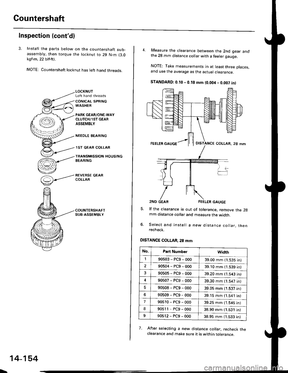
3. Install the parts below on the countershaft sub-assembty, then torque the locknut to 29 N.m (3.0kql.m , 22 blf.ftt .
NOTE: Countershaft locknut has left hand threads.
(=)-----'
v
LOCKNUTLeft hand threads
CONICAL SPRINGWASHER
PARK GEAR/ONE.WAYCLUTCH/1ST GEARASSEMBLY
NEEOLE BEARING
.I ST GEAR COLLAR
TRANSMISSION HOUSINGBEARING
REVERSE GEARCOLLAR
\
14-154
4. Measure the clearance between the 2nd gear andthe 28 mm distance collar with a feeler gauge.
NOTE: Take measurements in at least three places.and use the average as the actuar ctearance.
STANDAFD: 0.10 - 0.18 mm {0.004 - 0.002 inl
lf the clearance is out of tolerance. remove the 2gmm distance collar and measure the width.
Select and install a new distance collar, thenrecheck.
DISTANCE COLLAR, 28 mm
7. Afret selecting a new distance collar, recheck theclearance and make sure it is within tolerance.
OISTANCE COLLAR, 28 mm
No.Part Numb€rwidrh
190503-PCg-00039.00 mm (1.535 in)
290504-PCg-00039.10 mm { 1.539 in)
90505-PCg-00039.20 mm (1.543 in)
90507-PCg-00039.30 mm {1.547 in)
90508-PC9-00039.05 mm (1.537 in)
90509-PCg-00039.15 mm (1.541 in)
790510-PCg-00039.25 mm ( 1.545 in)
I90511-PCg-00038.90 mm (1.531 in)
90512-PCg-00038.95 mm (1.533 in)
Page 1205 of 2189
ABS Control Unit Terminal Arrangement
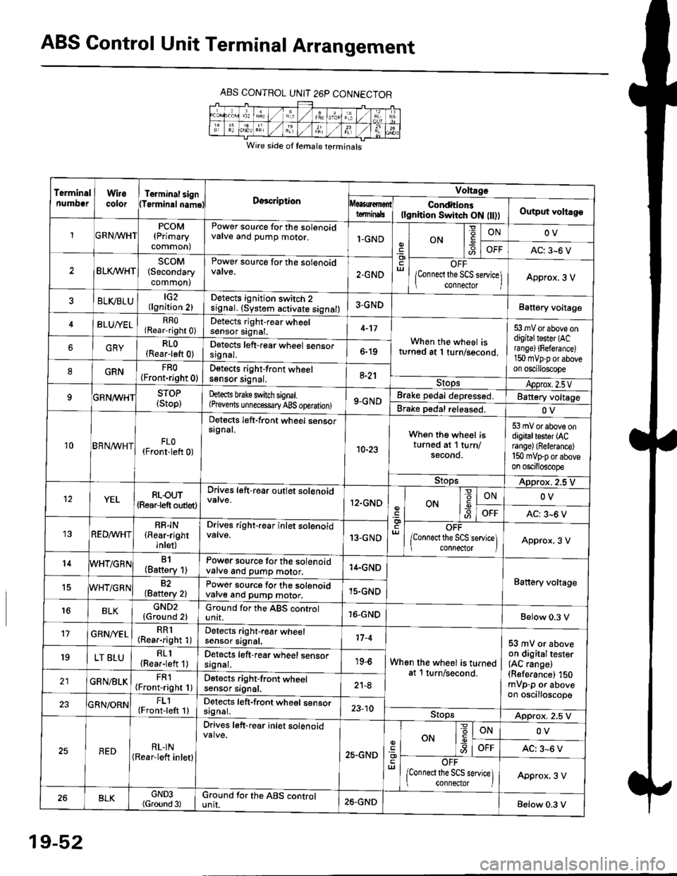
ABS CONTROL UNIT 26P CONNECTOR
Wire side of temale terminals
Terminalnumo0rWirecolorTerminal signTerminalnamoDgscriptionVoltage
Conditions(lgnition Switch ON flt))Output voltagoteminals
PCOM(Primary
common)
Power source for the solenoidvalve and pump motor.1-GNDON
=ONOV
AC: 3-6 V
BLK/WHTscoM(Secondary
common)
Power source for the solenoid
2.GNDOFF
lConnect the SCS service\
conneclor lApprox. 3 V
ELVBLUtG2(lgnition 2)Detects ignition switch 2
!9nal. (system activate signal)3-GNDBatt€ry voltage
BLU/YELRRO(Rear-right 0)Detects right-rear wheelsensor signal.4-17
When the wheel isturned at 1 turn/second.
53 mV or above ondigitaltester (ACra nge) {Fefera nce)150 mvp-p or aboveon oscilloscope
6GRYRLO(Rear-left 0)Detects left-rear wheel sensorsrgnal.6-19
8GRNFRO(Front-right 0)D€tects right-front wheelsgnsor srgnal,a-21StopsApprox.2.5VSTOP(Stop)hects brake switch signal.(Prevents unnecess€ry ABS operation)9-GNDBrake pedal depressed.Battery voltage
Brake pedal released.OV
10BRN^/vHTFLO(Front-left 0)
Detects left-front wheel sensorsignal.
10-23
When the wheel isturned at 1 turn/secono.
53 mV or above ondigitaltester (ACrange) (Referance)
150 mVFporaboveon oscilloscope
9!opsApprox. 2.5 V
12YELRLOUT(Rearjeft outlet)
Drives left-rear outlet solenoid
12.GNDON-9ONOV
OFFAC: 3^6 V
REDMHTRR]N(Rear-right
inlet)
Drives right-rear inlet solenoidvalve.13-GNDOFF
lconnect the SCS service]i connector IApprox. 3 V
14B1(Battery 1)Power source for the solenoidvatve and pump motor.14.GND
Battery voltage15WHT/G R N82(Baftery 2)Power source for the solenoidvarve ano pump motor.15.GND
r6BLKGND2{Ground 2)Ground for the ABS controlunit.16-GNDBelow 0.3 V
17GRN/'/ELRR1(Rear-right 1)Detects right-rear wheelsensor signal.17-4
When the wheel is turnedat 1 turn/second.
53 mV or aboveon digitaltester(AC range)(Referance) 150mVp-p or aboveon oscilloscope
19LT BLURLl(Rea.-left 1)Detects left-rear wheel sensorsagnal.19-6
GRN/BLKFRl(Front-right 1)Detects right-front wheelsensor signal.21-8
FL1(Front-left 1)Detects left-front wheel sensorsignal.23-10StopsApprox. 2.5 V
REDRL-IN(Rear-lett inletl
Drives left-r€ar inlet solenoid
25.GND
ut
ON
'6
-9ONOV
OFFAC: 3-6 V
OFF
lconnect the SCS service] connector lApprox. 3 V
BLKGND3(Ground 3)Ground for the ABS cgntrolunit.26.GNDBelow 0.3 V
19-52
Page 1206 of 2189
e\
t
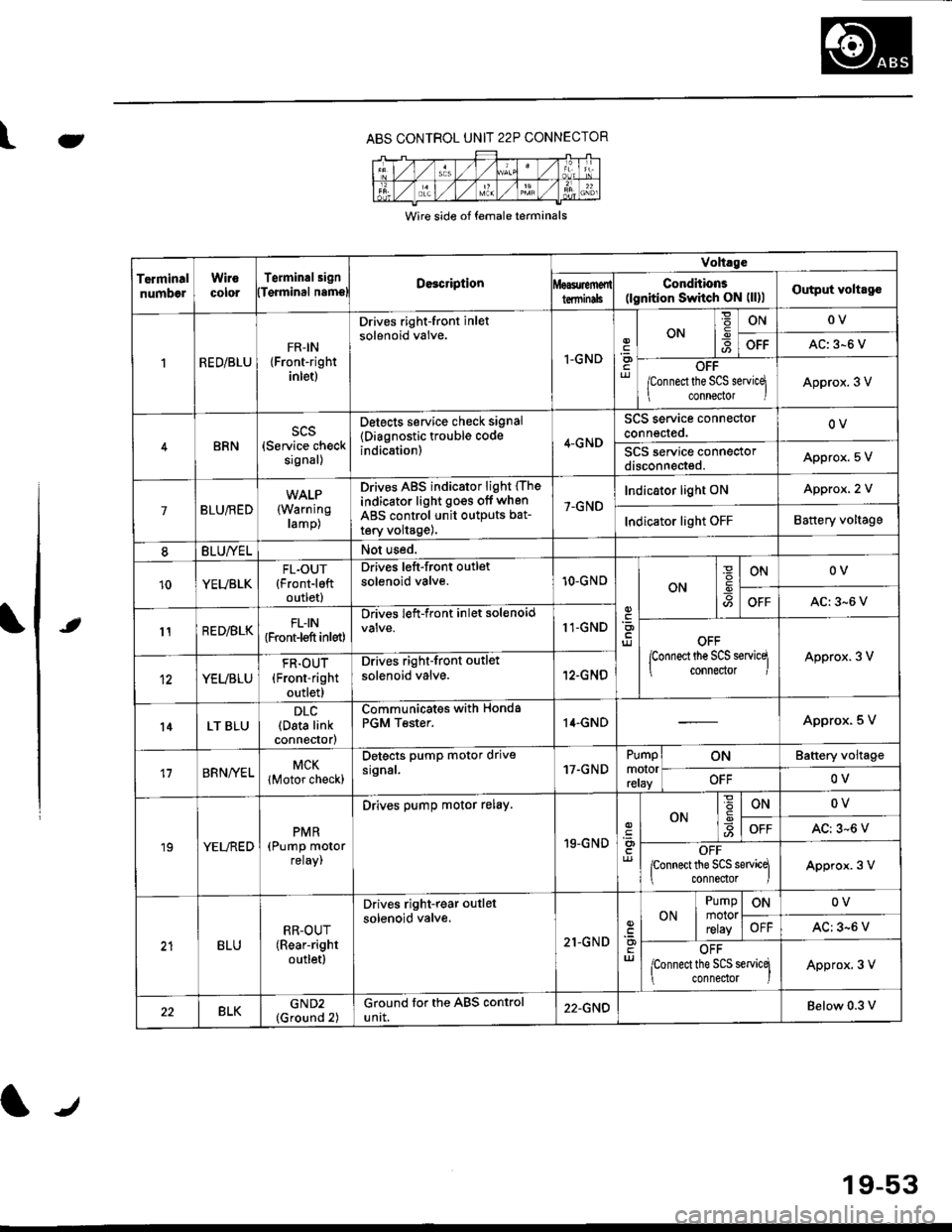
ABS CONTROL UNIT 22P CONNECTOR
Wire side of female terminals
TerminalnumbelWirocororTerminalsignDe3cription
Volt.ge
ConditionE(lgnition Switch ON (ll)lOutput voltagolTqrminal namslterminils
RED/BLUFR-IN{Front-rightinlet)
Drives right-front inletsolenoid valve.
I-GNDriJ
ON-9ONOV
OFFAC: 3-6 V
OFF
/Connect the SCS servicq
connector IApprox. 3 V
BRNscs(Service checksignal)
Detects service check signal
{Diagnostic trouble codeindication)4-GND
SCS service connectorconnected.OV
SCS service connectordisconneded.Appro)(. 5 V
7BLU/RED(Warning
ramp)
Drives ABS indicator light (The
indicator light go€s off when
ABS control unit outputs bat-
tery volta9e),
7-GND
Indicator light ONApprox, 2 V
Indicator light OFFBattery voltage
8BLU/YELNot used.
10YEUBLKFL.OUT{Front-leftoutlet)
Drives left-front outletsolenoid valve.10-GNOON
ONOV
OFFAC:3-6 V
11RED/BLKFLIN{Front-l€ft inlet)
Drives left-front inlet solenoid11-GNDOFF
lconnect the SCS servicq
connector IApprox. 3 V
YEUBLU
FR.OUT(Front-right
outlet)
Drives right-front outlet
solenoid valve.12-GNO
l4LT BLUDLC(Data linkconnector)
Communicates withPGM Tester.Honda14.GNDApprox. 5 V
17BRNA/ELMCK
lMotor check)
Detects pump motor drivesrgnal.17.GNDPumpmotorreray
ONBattery voltage
OFFOV
19YELREDPMR(Pump motorreray,
Drives pump motor relay.
19-GND
ONONOV
OFFAC: 3-6 V
OFFponnect the SCS sewicq
connedor lApprox. 3 V
BLURR-OUT(Rear-right
outletl
Drives right-rear outlel
solenoid valve.
21-GNDuJ
ON
Pumpmotorrelay
ONOV
OFFAC: 3-6 V
OFF
lconnect the SCS servicq
connedor )Approx. 3 V
22BLKGND2(Ground 2)Ground for the ABS controluntt.22-GNDBelow 0.3 v
19-53
Page 1321 of 2189
Seat Belts
Inspection
t.
Retractor InsDection
Before installing the retractor, check that the seat belt
can be pulled out freely.
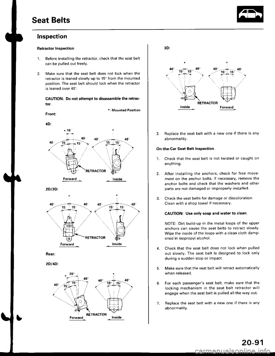
Make sure that the seat belt does not lock when the
retractor is leaned slowly up to 15'from the mounted
position. The seat belt should lock when the retractor
is leaned over 40'.
CAUTION: Do not attempt to disassemble the retrac-
tor.
Front:
*: Mounted Position
Inside
4D:
Forward
2D l3D.
Rear:
2D l4Di
* 10-
15 15'
i-Tl
I ],f
ForwaJdlnside
7.
20-91
3D:
ao"40'- -+ 40...'' 15' 15' --
(. .-j- ,)\,
RETRACTOR
3. Replace the seat belt with a new one if there is any
abnormality.
On-lhe-Car Seat Belt Inspeqtion
2.
3.
1.
5.
6.
4.
Check that the seat belt is not twisted or caught on
anyrn I ng.
After installing the anchors, check for free move
ment on the anchor bolts. lf necessary, remove the
anchor bolts and check that the washers and other
parts are not damaged or improperly installed
Check the seat belts for damage or discoloration.
Clean with a shop towel il necessary
CAUTION: Use only soap and water to clean.
NOTE: Dirt build-up in the metal loops of the upper
anchors can cause the seat belts to retract slowly.
Wipe the inside ot the loops with a clean cloth damF
ened in isopropyl alcohol.
Check that the seat belt does not lock when pulled
out slowly. The seat belt is designed to lock only
during a sudden stop or impact.
Make sure that the seat belt will retract automatically
when released.
For each passenger's seat belt, make sure that the
locking mechanism in the seat belt retractor will
engage when the seat belt is pulled all the way out.
Replace the seat belt with a new one il there is any
abnormality.
Page 1758 of 2189
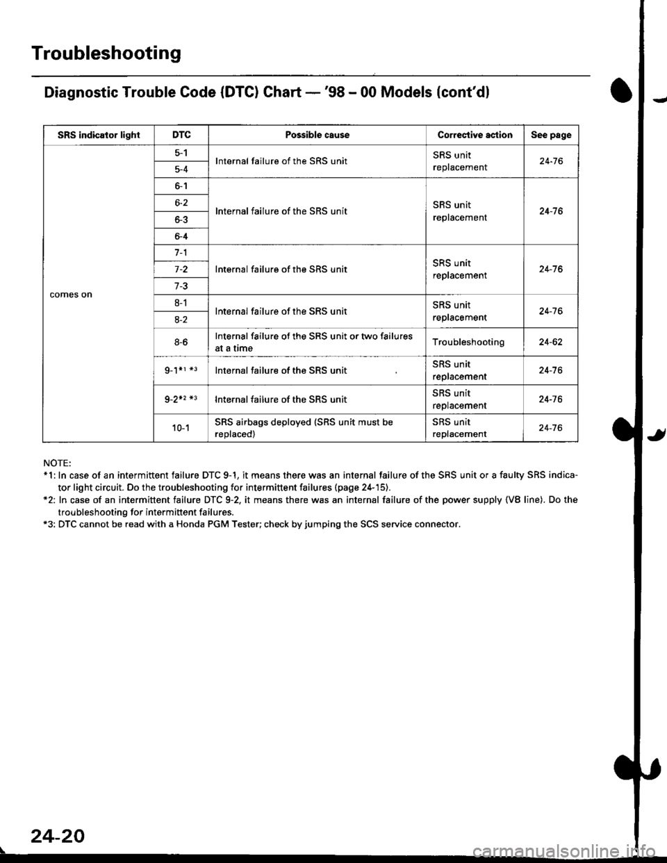
Troubleshooting
Diagnostic Trouble Code (DTC) Chart -'98 - 00 Models {cont'dl
NOTE:* 1: In case of an intermittent failure DTC 9-1, it means there was an internal failure of the SRS unit or a faulty SRS indica-
tor light circuit. Do the troubleshooting for intermittent failures (page 24-'15).*2: In case of an intermittent failure DTC 9-2, it means there was an internal failure of the power supply {VB line). Do the
troubleshooting for intermiftent failures.*3: DTC cannot be read with a Honda PGM Tester; check by jumping the SCS service connector.
24-20
\
SRS indicator lightDTCPossible causeCorrectiYe actionSee page
comes on
5-1lnternal failure of the SRS unitSRS unit
replacemenl24-765-4
6-1
lnternal failure of the SRS unitSRS unit
replacement24-7 66-2
o-5
6-4
7-1
lnternal failure of the SRS unitSRS unit
replacement24-76
7-3
8-1lnternal failure of the SRS unitSRS unit
reptacement24-7 68-2
8-6Internal failure of the SRS unit or two failures
at a trmeTroubleshooting24-62
g_1*r *3lnternal failure of the SRS unitSRS unit
replacement24-7 6
9-2+2 *3lnternal failure of the SRS unit5l|5 Untr
replacement24-76
10-1SRS airbags deployed (SRS unit must be
reDlaced)
SRS unit
replacement24-76
Page 1760 of 2189
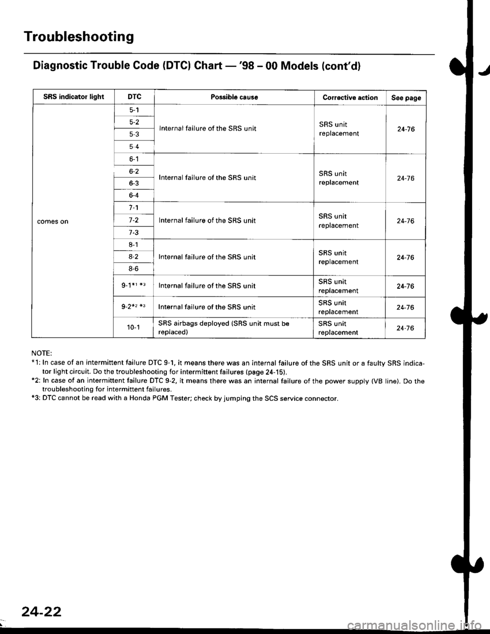
Troubleshooting
Diagnostic Trouble Code (DTCI Ghart -'98 - 00 Models (cont'd)
NOTE:*l: In case of an intermittent failure DTC 9-1. it means there was an internal failure of the SRS unit or a faultv SRS indica-
tor light circuit. Do the troubleshooting for intermiftent failures (pa9e 24-15).*2: In case of an intermittent failure DTC 9-2, it means there was an internal failure of the power supply (VB line). Do thetroubleshooting for intermittent failures.*3: DTC cannot be read with a Honda PGM Tester; check by jumping the SCS service connector.
SRS indicator lightDTCPossible causeCorective actionSeo page
comes on
5-2
53
54
lnternal failure of the SRS unitSRS unit
replacement24-7 6
6-1
6-2
_
64
Internal failure of the SRS unitSRS unit
replacement24-16
n
-
8l
8S
9_1*r *3
Internal failure of the SRS unitSRS unit
reptacement24-76
Internal failure of the SRS unitSRS unit
replacement24-76
Internal failure of the SRS unitSRS unit
replacement24-76
Internal failure of the SBS unitSRS unit
reptacemenr24-76
10-1SRS airbags deployed (SRS unit must be
reDlaced)
SRS unit
replacement24-76
24-22
Page 1762 of 2189
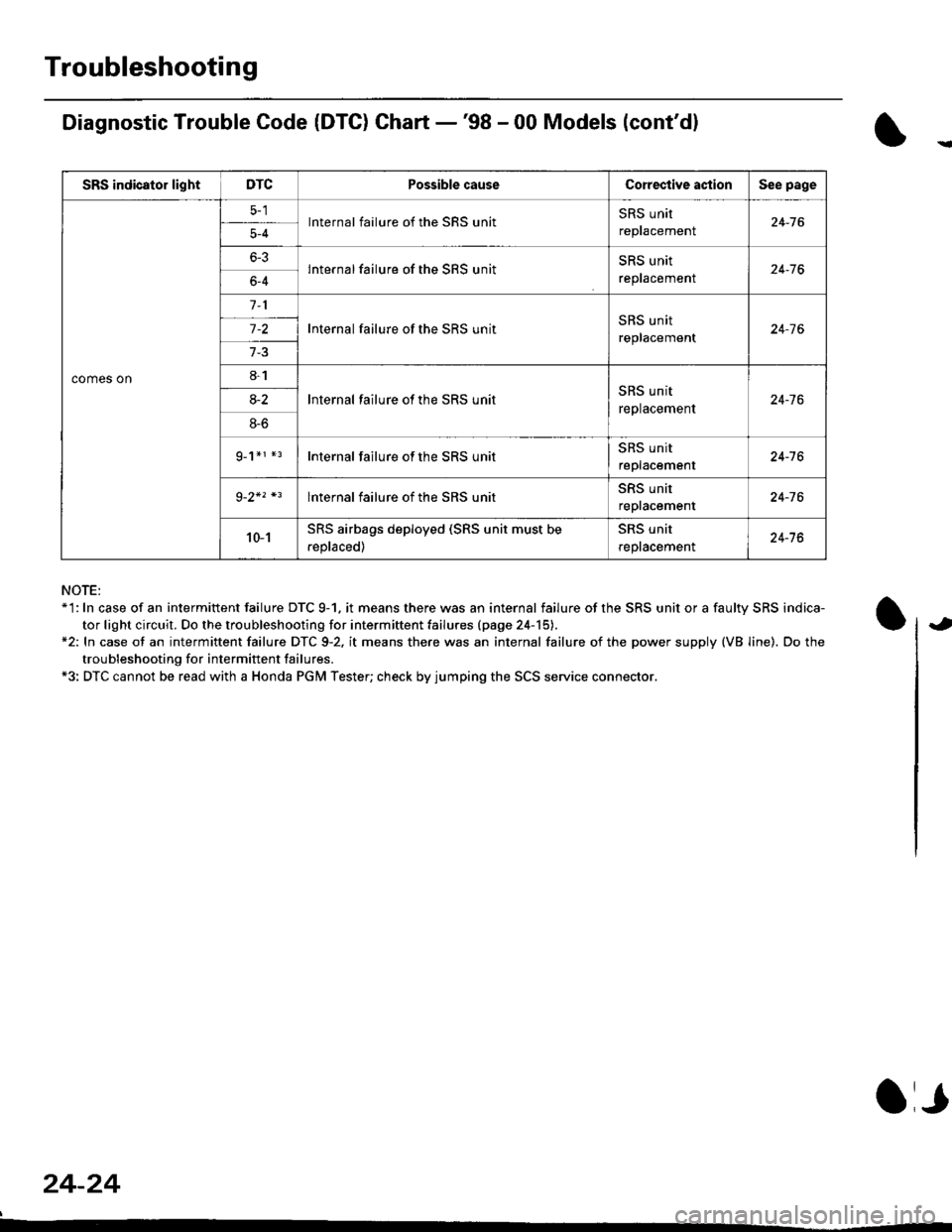
Troubleshooting
Diagnostic Trouble Code (DTG) Chart -'98 - 00 Models (cont'dl
NOTE:*'l: In case of an intermittent failure DTC 9-1. it means there was an internal failure of the SRS unit or a faulty SRS indica-
tor light circuit. Do the troubleshooting for intermiftent failu.es (page 24-15).*2: In case ot an intermittent failure DTC 9-2. it means there was an internal failure of the power supply (VB line). Do the
troubleshooting for intermift ent failures.*3: DTC cannot be read with a Honda PGM Tester; check by jumping the SCS service connector.
24-24
a,
SRS indicator lightDTCPossible causeCorective actionSee page
comes on
lnternal failure of the SRS unitSRS unit
repracemenl24-765-4
6-3lnternal failure of the SRS unitSRS unit
reptacemenr24-766-4
Internal failure of the SRS unitSRS unit
replacement24-7 6
8-1
lnternal failure ot the SRS unitSRS unit
replacement24-7 68-2
8-6
g_1*r *rInternal failure of the SRS unitSRS unit
replacement24-16
lnternal failure of the SRS unitSRS unit
repracemenl24-76
10-1SRS airbags deployed (SRS unit must be
.eplaced)
SRS unit
reptacemenl24-76