Page 1039 of 2189
Driveshafts
Disassembly (cont'dl
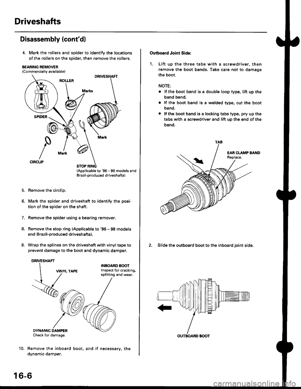
4. Mark the rollers and spider to identify the locations
of the rollers on the sDider, then remove the rollers.
B€ARING REMOVER{Commerciallv available}
STOP RING(Applicable to '96 - 98 modols andErazil-produced driveshafts)
Remove the circlip.
Mark the spider and driveshaft to identify the posi-
tion ot the spider on the shaft.
Remove the spider using a bearing remover.
Remove the stop ring (Applicable to '96 - 98 models
and Brazil-produced driveshafts).
Wrap the splines on the drivsshaft with vinyl tape to
prevent damage to the boot and dynamic damper.
DRIVESHAFT
1.
VINYL TAPE
DYNAMIC DAMPERCheck for damage.
Remove the inboard
dynamic damper.
INBOARO AOOTInspect for cracking,splitting and wear.
16-6
boot, and if necessary, the
Outboard Joint Side:
1. Lift up thc three tabs with a screwdriver, then
remove the boot bands, Take care not to damage
the boot.
NOTE:
. lf the boot band is a double loop type, lift up the
band bend.
. lf the boot band is a welded type, cut the boot
band.
. lfthe boot band is a locking tabs type, pry up the
tabs with a scr€wdriv€r and lift uo the snd of the
band.
2. Slide the outboard boot to the inboard ioint side.
TAB
OUTBOABD BOOT
Page 1043 of 2189
Driveshafts
Reassembly (cont'dl
Japan-Produced Driveshafts
Note these items during reassembly.
. Clean the disassembled pans with solvent, and dry them thoroughly with compressed air. Do not wash the rubber
parts with solvent.
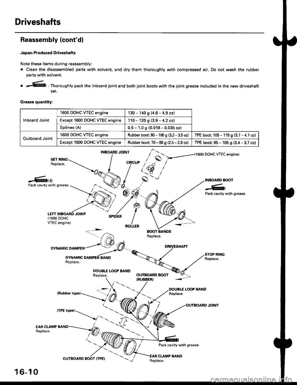
o r@l : Thoroughly pack the inboard joint and both joint boots with the joint grease included in the new driveshaft
set.
Grease quantity:
Inboard Joint
1600 DOHC WEC engine130 - 140 9 (4.6 - 4.9 oz)
Except 1600 DOHC VTEC engine110 - 120 g (3.9 - 4.2 oz)
Splines (Al0.5 - 1.0 g (0.018 - 0.035 oz)
Outboard Joint
'1600 DOHC WEC engineRubber boot 90 - 'l 00 g (3.2 - 3.5 oz)TPE boot; 105 - 115 9 (3.7 - 4.1 oz)
Except 1600 DOHC VTEC engineRubber boot 70 - 80 g |'2.5 - 2.8 ozlTPE boot 95 - 105 g (3.4 - 3.7 oz)
{1600 DOHC VTEC angine)
SET RINGReplace.
-6{@INBOARD BOOT
-6;Pack cavity with grease.
Pack cavity with grease.
DYNAMIC DAMPER
DYNAMICReplace.
DOUA|.I Lq)P BANDReplace.
(Rubber typc)LOOP BANDReplace.
Pack cavity with grease-
CLAMP BAND
],*"u, ,"^S
/ t'.t$ ,''
,/s
-'-
OUTBOARD BOOTIRUEBER)
16-10
tttt t*' -----_.r...-
._
Replace.
Page 1044 of 2189
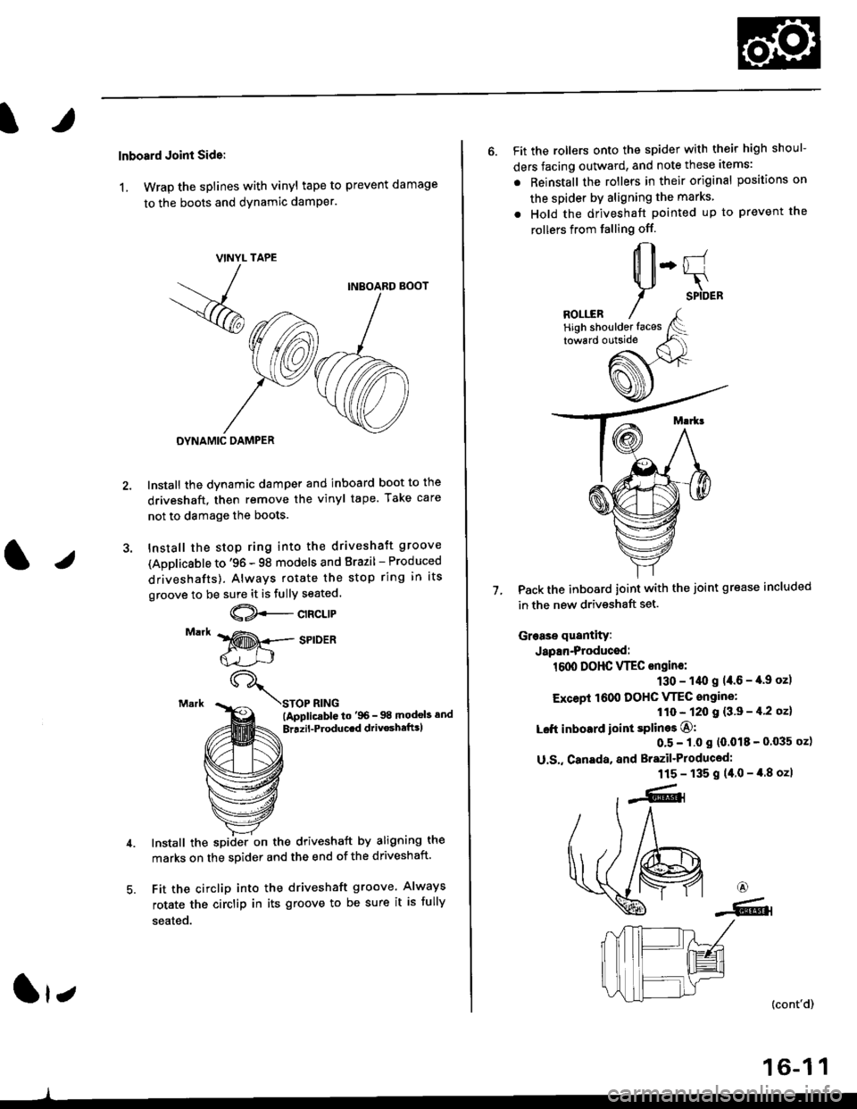
lnboard Joint Side:
1, Wrap the splines with vinyl tape to prevent damage
to the boots and dynamic damPer.
TAPE
INBOARD BOOT
DYNAMIC DAMPER
Install the dynamic damper and inboard boot to the
driveshaft, then remove the vinyl tape. Take care
not to damage the boots.
Install the stop ring into the driveshaft groove
(Applicsble to '96 - 98 models and Brazil - Produced
driveshafts). Always rotate the stop ring in its
groove to be sure it is fully seated.
@--c't"t't
STOP RING(ApplicablG to'96- 98 modob and
Brrzil-Producrd drivoshaftrl
Install the spiiler on the driveshaft by aligning the
marks on the sDider and the end of the driveshaft.
Fit the circlip into the driveshaft groove. Always
rotate the circlip in its groove to be sure it is fully
seated.
VINYL
- -
/
-<@
lr;
6. Fit the rollers onto the spider with their high shoul-
ders facing outward, and note these items:
. Reinstall the rollers in their original positions on
the spider by aligning the marks
. Hold the driveshaft pointed up to prevent the
rollers from falling off.
Pack the inboard joint with the joint grease included
in the new driveshaft set.
Grease quantity:
Japan-Produced:
1600 DOHC VTEC ongine:
130 - 1/t0 g 14.6 - '[.9 oz)
Except 1600 DOHC VTEC angine:
110 - 120 I {3'9 - il'2 oz}
Left inboard ioint splines O:
0'5 - 1.0 s (0.018 - 0'035 oz)
U.S,, Canada, and Brazil'Produced:
115 - 135 g (40-4.8ozl
7.
6
-6.l
(cont'd)
16-1 1
High shoulder faces
Page 1047 of 2189
Driveshafts
17.
Reassembly (cont'dl
Unwind the boot band tool, and cut off the excess 5- 10 mm (0.2 - 0.4 in) from the clip.
5-10mm10.2 - 0.a inl
Secure the end of the boot band by tapping it downwith a hammer,
19. Installthe new set ring,
18.
Note these items after reassembly:. Make sure the band and clip does notanything and the band does not move.a Remove any grease remaining on thesurfaces.
interfere with
su rrou nding
16-14
Outboard Joint Sid.:
1. Wrap the splines with vinyl tape to prevent damageto the boot.
TPE tvDe:-. OUTBOARO BOOT ITPE)
BOOT BANDReplac€,
Rubber typ.:
Install the boot band and outboard boot, thenremove the vinyl tape. Take care not to damage theboot,
Install the stop ring into the driv€shaft groove.
DRIVESHAFT
>VINYL TAPE
VINYL TAPE
Page 1057 of 2189
l.
t
Steering
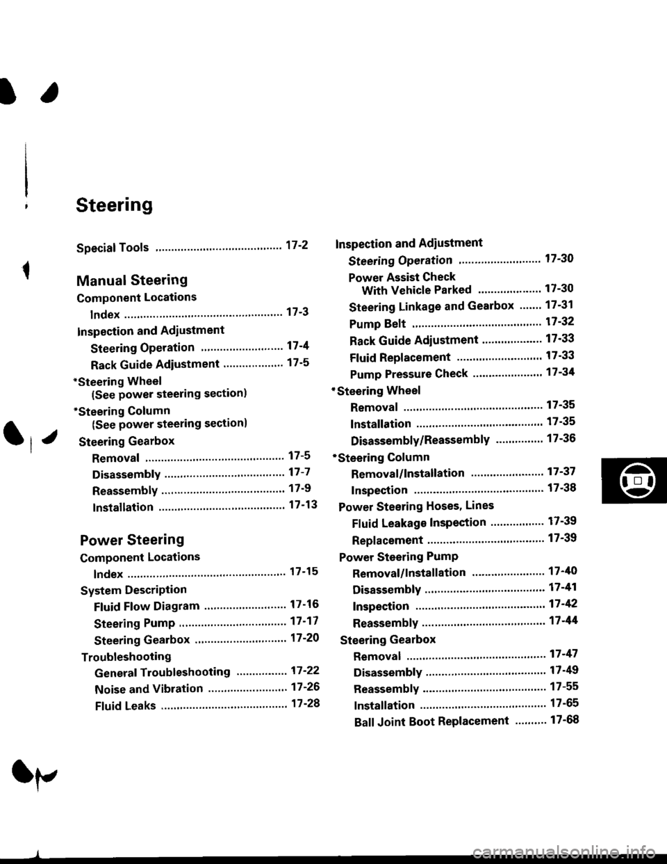
Speciaf Tools ....."'.....17-2
Manual Steering
Component Locations
lndex ................ ....... 17-3
Inspection and Adiustment
Steering Operation "'......"............... 17-4
Rack Guide Adiustment ................... 17-5
*Steering Wheel
(See power steering section)
*Steering Column
(See power steering sectionl
Steering Gearbox
Removal ................. 17-5
Disassembly ......."" 17-7
ReassemblY ..'......... 17-9
lnstallation ............. 17-13
Power Steering
Component Locations
lndex "......."..... """' 17-15
System DescriPtion
Fluid Flow Diagram .........""............. 17'16
Steering Pump ............'... "........"'...-- 17 -17
Steering Gearbox .".................'...'.'.' 17-20
Troubleshooting
Generaf Troubleshooting ..........--.... 17'22
Noise and Vibration ......................... 17 -26
Ffuid Leaks .............17-28
Inspection and Adiustment
Steering Operation'......."'........'...... 1 7-30
Power Assist Check
With Vehicle Parked .."................ 17-30
Steering Linkage and Gearbox ....." 17-31
Pump Beft ...--.""".. 17-32
Rack Guide Adiustment .'.......'.......'. 17'33
Fluid Replacement .....'.."................. 17-33
Pump Pressure Check .............'....-. " 17 -34
'Steering Wheel
Removal .."'........'... 17-35
lnstallation ............. 17-35
Disassembly/Reassembly ......'.....'.' 17-36
*Steering Column
Removal/lnstallation ....'........... ---.... 17'37
lnspection .............. 17'38
Power Steering Hoses, Lines
Fluid Leakage Inspeetion ............'.... 17-39
Replacement ......".. 17-39
Power Steering PumP
Removal/lnstallation .'.'..'..'............. 17-40
Disassembly ".........17-41
fnspection .......---'." 17'42
Reassembly ..'.........17-44
Steering Gearbox
Removal ....'........."' 17'47
DisassemblY ..........' 17-49
Reassembly '........... 17-55
lnstallation ............. 17-65
Ball Joint Boot Replacement .......'.. 17-68
Ir/
lp
Page 1069 of 2189
)
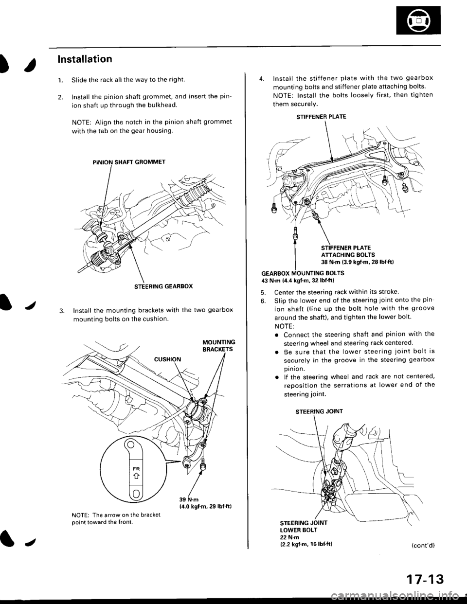
lnstallation
Slide the rack all the way to the righl
Install the pinion shaft grommet, and insert the pin
ion shaft up through the bulkhead.
NOTE| Align the notch in the pinion shaft grommet
with the tab on the gear housing.
1.
2.
J3. Install the mounting brackets with the two gearbox
mounting bolts on the cushion.
NOTE: The arrow on the bracketpoint toward the front.
STEEBING GEARBOX
{4.0 kgt.m,29 lbf.ftl
J
4. Install the stiffener plate with the two gearbox
mounting bolts and stiffener plate attaching bolts.
NOTEr Install the bolts loosely first. then tighten
them securely.
GEARBOX MOUNTING EOLTS43 N.m {4.4 kgf.m, 32 lbf'ftl
5. Center the steering rack within its stroke
6. Slip the lower end ot the steering joint onto the pin
ion shaft (line up the bolt hole with the groove
around the shaft), and tighten the lower bolt.
NOTE:
. Connect the steering shaft and pinion with the
steering wheel and steering rack centered
Be sure that the lower steering joint bolt is
securely in the groove in the steering gearbox
pin ion.
lf the steering wheel and rack are not centered,
reposition the serrations at lower end of the
steering ioint.
STEERING JOINT
STEERING JOINTLOWER BOLT22 N.m{2.2 kgf.m, 16lbf'ft}(cont'd)
I t- t5
STIFFENER PLATE
ATTACHING BOLTS38 N.m (3.9 kgf.m.28lbf.ftl
Page 1076 of 2189
System Description
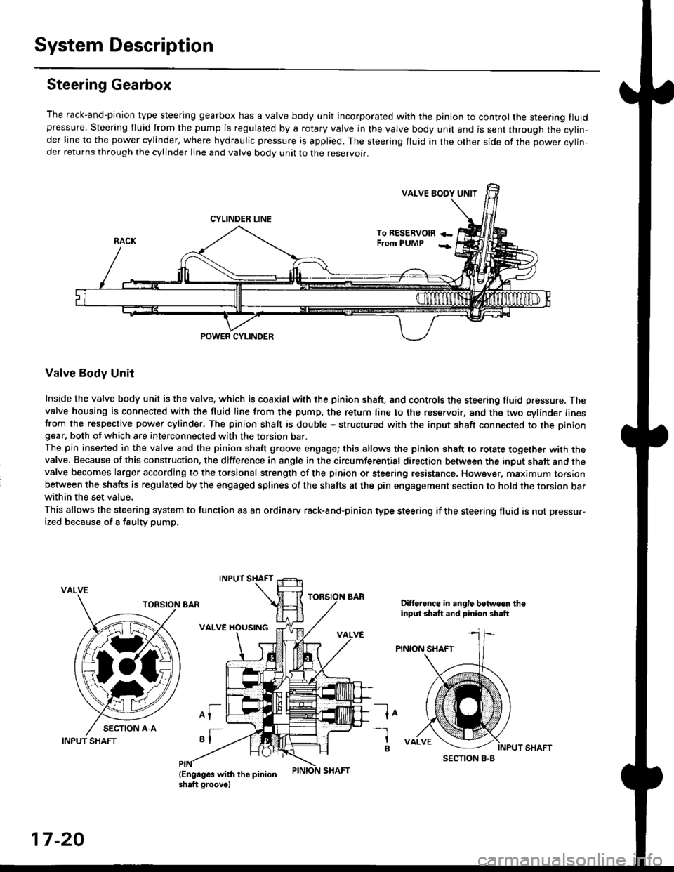
Steering Gearbox
The rack-and-pinion type steering gearbox has a valve body unit incorporated with the pinion to control the steering fluidpressure. Steering fluid from the pump is regulated by a rotary valve in the valve body unit and is sent through the cylin,der line to the power cylinder, where hydraulic pressure is applied. The steering fluid in the other side of the power cylin,der returns through the cylinder line and valve body unit to the reservoii.
VALVE EODY UNIT
CYLINDER LINE
To RESERVOm +-From PUMP -;
POWER CYLINDER
Valve Body Unit
Inside the valve body unit is the valve, which is coaxial with the pinion shaft, and controls the steering fluid pressure. Thevalve housing is connected with the fluid line from the pump, the return line to the reservoir, and the two cylinder linesfrom the respective power cylinder. The pinion shaft is double - structured with the input shaft connected to the piniongear, both of which are interconnected with the torsion bar.
The pin inserted in the valve and the pinion shaft groove engage; this allows the pinion shaft to rotate together with thevalve. Because of this construction, the difference in angle in the circumferential direction between the input shaft and thevalve becomes larger according to the torsional strength of the pinion or steering resistance. However, maximum torsionbetween the shafts is regulated by the engaged splines of the shafts at the pin engagement section to hold the torsion barwithin the set value,
This allows the steering system to function as an ordinary rack-and-pinion type steering if the steering fluid is not pressur-
ized because of a faulty pump,
VALVE
Difforence in angle botwoon theinput shaft and pinion shsft
PINION SHAFT
lo
INPUT SHAFT
-l
a
17-20
INPUT SHAFT
Page 1078 of 2189
Troubleshooting
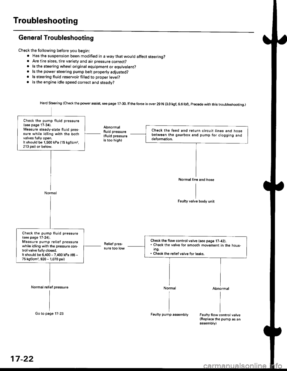
General Troubleshooting
Check the following before you begin:. Has the suspension been modified in a way that would affect steering?. Are tire sizes, tire variety and air pressure correct?. lsthe steering wheel original equipment or equivalent?. lsthe powersteering pump belt properlyadiusted?
. ls steeringfluid reservoirfilledto proper level?. ls the engine idle speed correct and steady?
Hard Steering (Check the powor assist. se€ page 17-3o. lfthe torce is over 29 N (3.0 kgf, 6.6lbo, Procede with this troubleshootinq.)
Abnormallluid pressure
{fluid pressureis too high)
Faulty valve body unit
Relief pres-sure too low
Abnormal
Faulty llow control valve(Replace the pump es anassembly)
Ch€ck the feed snd return circuit lin€s ano nosebetw6€n the gearbox and pump for clogging andd€lormation.
Normal line and hose
Check the pump fluid pressure(soe page 17-34).l/easure steady-state tluid pres-s!re while idling with the bothvalves tully open.It should be 1.500 kPa (15 kgf/cmr,213 psi) or below.
Normal
Check th€ flow control vslve (see page 17-42).. Chock the valvo lor smooth movement in the hous-ing.. Check the reliefvalve for leaks.
Check the pump fluid pressure
{see page 17-34).Measure pump relief pressurewhile idling with the pressure con-trol valve Iully closed.It should be 6,400 - 7,400 kPa (65 -
75 kgflcm,,920 - 1,070 psi)
Normal relisf pressure
17-22
Go to page 17-23Faulty pump assembly