Page 1585 of 2189
-
Wire side offemale terminals
LtwHT/8LUl
ALTERNATOR 3P CONNECTOR
lCanada)
Wire side oftemale terminals
LIWHT/BLUI
L
{W}IT/BLU)
.+1lr l2l
l3T.l-l-
ir/
(WHT/BLUI
(cont'd)
23-115
{From previous page)
Check tor an open in tho L cir'
cuit-1:1. Turn the ignition switch OFF
2. Disconnect the 4P [3Pl con-
nector from the alternator.
3. Ground the No. 3 terminal of
the 4P l3Plconnector.4. Turn the ignition switch ON (ll)
Turn the ignition swhch OFF, and
rep.ir tho open in tho wHT/
BLU wire.
Does the charging system
light come on?
Check for an open in the L cir-
cuit-2:Disconnect the No 3 terminal o{
the 4P [3PI connector from theground.
Does the charging system
light go off.r
Turn lhe ignition 3whch OFF, and
.epair the 3hort to gtound in the
wHT/Bl-U wire.
ALTERNATOR 4P CONNECTOR(USAI
r?-rl1l2l
FFI
]--
I
I l: canada
Page 1586 of 2189
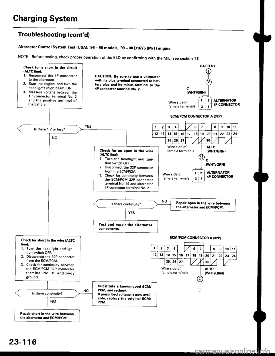
Charging System
Troubleshooting (cont'd)
Alternator Control System Test (USA): ,96 - 98 modets, ,99 _ 00 Dl6y5 (M/Tl engine
NorE: Before testing. check proper operation of the ELD by confirming with the MrL {see section r 1).
BATTERY
CAUTION: Be 3ure to use a voltmot€.with its plus terminal connected to b.t-tery plus and its minus terminal to the{P connectoi tgmrinal No. 2.c
{WHT/GRNt
Wire side oIfemale terminals
ALTERNATOR.P CONNECTOB
Check for a 3hort in the circuitIALTC linel:1. Reconnect the 4P connectorto the alternator,2. Stan the engine, and turn theheadlights {high beam) ON.3. Measure voltage between the4P connector terminal No. 2and the positive terminal ofthe battery.
ls there 1V or less?
Check for rn opon in tha wire(ALTC linol:1. Turn the headlight and igni-tion switch OFF.2. Disconnect the 32P connectortrom the ECM/PCN4.3. Check tor continuity betweenthe ECM/PCM 32P connectorterminal No. 19 and alternator4P connector terminal No. 2.
Bspair open in thg wire lrstweenthe rhern.tor .nd ECM/PCM.
Check for short in the wire (ALTClinel:1. Turn the headlight and ignition switch OFF.2. Disconnect the 32P connectortrom the ECM/PCM.3. Check tor continuity betweenthe ECM/PCM 32P connectorterminal No. 19 and bodyground.
Subslitute a known-good ECM/PCM, .nd .och6ck.It p.escribod vohago i! now avail-able, replace the original ECM/PCM.
Ropair 3hort in the wiro betweonthe ahe.nator and ECM/PCM.
ECM/PCM CONNECTOR A I32PI
'Ia18I1011
121314151718t9
7
202'l2221
262730
Wire side offemale terminalsALTC(WHT/GRNI
c{WHT/GRNI
ALTERNATORWire side oIfemale terminals
([l
T
12
1
ECM/PCM CONNECTOB A (32PI
I23478910t1
1213 14151617182021222321
262730
Wire side of I AITCfemate terminats
A
(WHT/GRN|
23-116
Page 1587 of 2189
-
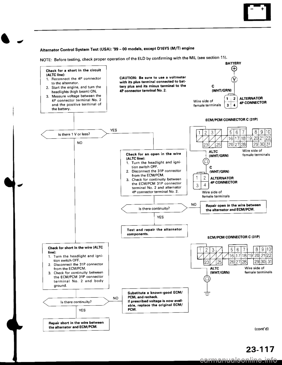
Alternator Control System Test {USA}: '99 - 0O models, except Dl6Y5 {M/T} engine
NOTE: Before testing, check proper operation ofthe ELD by confirming with the MIL (see section 11)'
BATTERY
CAUTION: Be sura lo use a voltmeter
with its plus te.minal conneqted io bat-
tery plus and it3 minus tgrminal to ths
4P connoctot tomrinal No. 2.
Wire side of
female terminals
c(WHT/GRNI
wire side offemale terminals
ALTERNATOR.P CONNECTOR
ECM/PCM CONNECTOR C 13lPI
ECM/PCM CONNECTOR C (31PI
(cont'd)
23-117
Check lor a sho.t in the circuit
{ALTC line):1, Beconnect the 4P connector
to the alternator.
2. Start the engine, and turn the
headlights (high beam) ON.
3. Measure voltage between the
4P connector terminal No. 2
and the Positive terminal of
the battery.
ls there 1 V or less?
Chcck for rn opon in the wire(ALTC lin6l:1. Turn the headlight and igni-
tion switch OFF
2. Disconnect the 31P connector
trom the ECM/PCM.
3. Check for continuity betlveen
the ECM/PCM 31P connectorterminal No. 2 and alternator
4P connector terminal No. 2
Repair opcn in the wire botweon
the alternstoi.nd ECM/PCM.ls there continuity?
Check tor short in the wire IALTC
line):1. Turn the headlight and igni-
tion switch OFF2. Disconnect the 31P connector
from the ECM/PCM.
3. Check for continuity between
the ECM/PCM 31P connector
terminal No. 2 and body
ground.
Substitute a known'good ECM/
PCM, and recheck.It prscribed voltagg is now avail'
abl€, replace tho original ECM/
PCM.
Raoair short in the wite between
the alle.nator and ECM/PCM,
1235618I10
/11611lo191 zo2122
23252621?82930JI
ALTC Wire side of(WHT/GRN) female terminals
o
Page 1588 of 2189
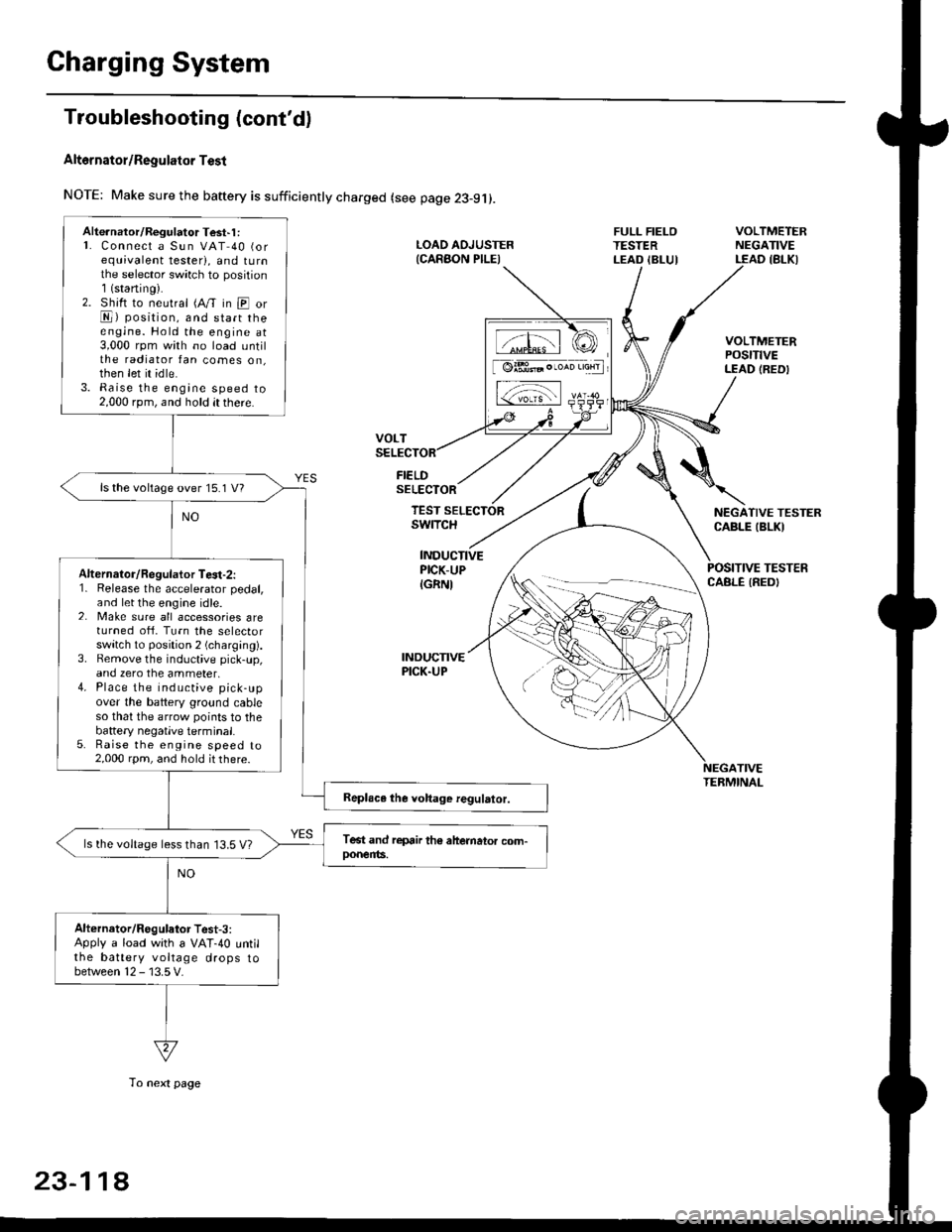
Charging System
Troubleshooting (cont'd)
Alt6rnator/Regulator Test
NOTE: Make sure the baftery is sufficiently charged (see page 23-9j).
FIELDSELECTOR
LOAD AOJUSTER{CARAON PILEI
FULL FIELOTESTERLEAD IBLUI
VOLTMETERNEGATIVELEAD IBLKI
VOLTMETERPOStTtVELEAD (REDI
NEGATIVE TESTERCABLE IBLKI
POSITIVE TESTERCABLE IREDI
TEST SELECTORswrTcH
INDUCTIVEPICK-UP
IGRNI
INDUCNVEPICK.UP
TIVETEBMINAL
Alte.nator/Regulator Test'1 :L Connect a Sun VAT 40 (orequivalent tester), and tu rnthe selector sw;tch to position1(staning).2. Shift to neutral (A/T in E orE) position, and start theengine. Hold the engine at3,000 rpm with no load untilthe radiator fan comes on,then let it idle.3. Raise the engine speed to2,000 rpm, and hold it there.
ls the voltage over 15.1 V?
Alternalor/Regulator Te3t-2:1. Release the accelerator pedal,and let the engine idle.2. Make sure all accessories areturned ofi. Turn the selectorswitch to position 2 (charging).3. Bemove the inductive pick-up,and zero the ammeter,4. Place the inductive pick-upover the battery ground cableso that the arrow points to thebattery negatlve terminal.5. Raise the engine speed to2,000 rpm, and hold it there.
ls the voltage less than 13.5 V?
Alternator/Regulator Test-3:Apply a load with a VAT-40 untilthe battery voltage drops tobetween 12 - 13.5 V.
tffil rCI
[ @lBt* . ,*n 'aHrl
L-;-;l rs-
23-11A
To next page
Page 1592 of 2189
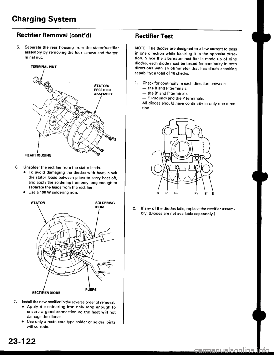
Charging System
Rectifier Removal (cont'd)
Separate the rear housing from the stator/rectifier
assembly by removing the four screws and the ter-minal nut.
TERMINAL NUT
Unsolder the rectifier from the stator leads,. To avoid damaging the diodes with heat, pinch
the stator leads between pliers to carry heat off,and apply the soldering iron only long enough toseparate the leads from the rectifier.. Use a 100 W soldering iron.
STATOR SOLDERING
7. Install the new rectifier in the reverse order of removal.. Apply the soldering iron only long enough toensure a good connection so the heat will notdamage the diodes.
a Use only a rosin core type solder or solder joints
will corrode.
6.
SOLDERING
23-122
Rectifier Test
NOTE: The diodes are designed to allow current to pass
in one direction while blocking it in the opposite direc-tion. Since the alternator rectifier is made up of ninediodes, each diode must be tested for continuity in bothdirections with an ohmmeter that has diode checkinocapability; a total of 18 checks.
1. Check for continuity in each direction between- the B and P terminals.- the B'and P terminals.- E {ground) and the P terminals.
All diodes should have continuity in only one direc-UOn.
lf any of the diodes fails, replace the rectifier assem-bly, (Diodes are not available separately.)
Page 1610 of 2189
Vehicle Speed Sensor (VSSI
Troubleshooting
Before testing, inspect the No. 15 (7.5 A) fuse in the under-dash fuse/relay box.
TEST HARNESSOTLAJ _ PT3O2OAREO TEST HARNESSCLIP
PROTECTIVETAPE
TEST HARNESSOTLA' . PT3O2OA
(To next page)
Test the BLK wire:1. Disconnect the 3P connectorfrom the vehicle speed sensor(vss).
2. Connect the test harness(07LAJ PT30200) only to theengine wire harness,3. Connect the RED test harnessclip to the positive probe of a
4. Check for continuity betweenthe RED test harness clip andbody ground.
Repair opon in the BLK wireb€twe€n the VSS and G101.ls there continuity?
Te3t the BLK/YEL wire:1. Connect the WHT test harnessclip to the positive probe of avoltmeter, and connectthe REDtest harness clip to the negativeprobe.2. Turn the ignition switch ON {ll).
Repair open in iho BLK/YEL wirebetween the VSS and the under-d6sh tuse/relav box.
vss
GRN TEST HARNESS
RED TEST HARNESS
WHT TEST HARNESS CLIP
23-140
Page 1611 of 2189
J
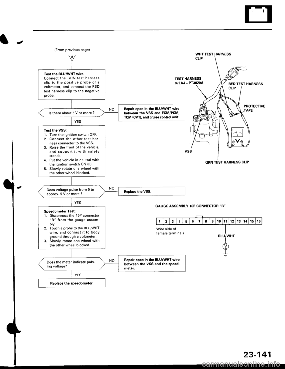
(From prevaous page)
WHT TEST HARNESSCLIP
TEST HABNESS07LAJ - Plil020aRED TEST HARNESSCLIP
PROTECTIVEAPE
GRN TEST HARNESS CLIP
GAUGE ASSEMBLY 16P CONNECTOR "8"
BLU
23-141
Tost the BLU/WHT wireiConnect lhe GRN test harnessclip to the positive probe of avoltmeter, and connect the RED
test harness clip to the negativeprobe.
Repair open in the BLU/WHT wirob€twoon the VSS and ECM/PCM,TCM (CVT), and cruise control untt.ls there about 5 V or more ?
Test the vss:1. Turn the ignition switch OFF.2. Connect the other test harness connector to the VSS.3. Raise the front ot the vehicle,and support it with safetystands,4. Put the vehicle in neutral with
the ignition switch ON (ll).
5. Slowly rotate one wheel withthe other wheel blocked.
Does voltage pulse from 0 toapprox.5 V or more ?
Speedometer Tosii'1. Disconnect the 16P connector"B" from the gauge assem-blv.2. Touch a probe to the BLUMHTwire, and connect it to bodyground through a voltmeter.
3. Slowly rotate one wheel with
the other wheel blocked.
Repair open in the BLU/WHT wi.ebelween th€ VSS and the 3pe€d-Does the meter indicate puls-
ing voltage?
female terminals
Page 1612 of 2189
Fuel Gauge
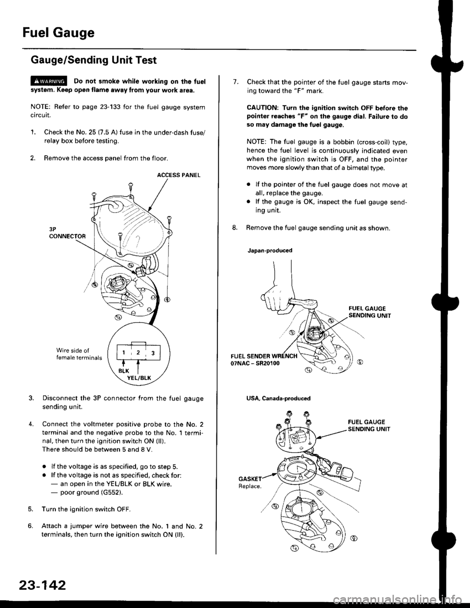
Gauge/Sending Unit Test
!@ Do not smoke while working on tho fuel
system. Keep open tlame away trom your wotk atea.
NOTE: Refer to page 23-133 for the fuel gauge system
circuit.
'1. Check the No. 25 (7.5 A) fuse in the under-dash fuse/
relay box before testing.
2. Remove the access panel from the floor.
ACCESS PANEL
Disconnect the 3P connector from the fuel gauge
sending unit.
Connect the voltmeter positive probe to the No. 2
terminal and the negative probe to the No. I termi-
nal, then turn the ignition switch ON (ll).
There should be between 5 and 8 V.
. lf the voltage is as specified, go to step 5.
. lf the voltage is not as specified. check for:- an open in the YEUBLK or BLK wire.- poor ground (G552).
Turn the ignition switch OFF.
Attach a jumper wire between the No. 1 and No. 2
terminals, then turn the ignition switch ON (ll).
)\
23-142
1.Check that the pointer of the fuel gauge starts mov-
ing toward the "F" mark.
CAUTION: Turn the ignition switch OFF before thepoinier reaches "F" on ihe gauge dial. Failure to do
so may damage the fuel gauge.
NOTE: The fuel gauge is a bobbin (cross-coil) type,
hence the fuel level is continuously indicated even
when the ignition switch is OFF, and the pointer
moves more slowly than that of a bimetaltype.
. lf the pointer of the fuel gauge does not move at
all, replace the gauge.
. lf the gauge is OK. inspect the fuel gauge send-
ing unit.
Remove the fuel gauge sending unit as shown.
Japan-produced
USA, Canada-produced