1999 HONDA CIVIC Lug nut
[x] Cancel search: Lug nutPage 64 of 2189
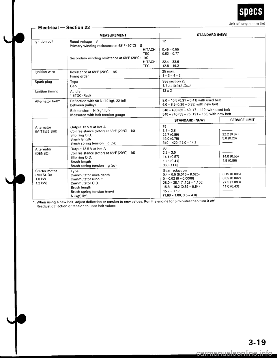
ElectricalSection 23
*: When using a new belt, adjust deflection or tension to new values. Run the engine for 5 minutes then turn it off
Readiust deflection or tension to used belt values
Unit of englh: mm {n)
MEASUREMENTSTANDARD {NEW}
lgnition coilRated voltage VPrimary winding resistance at 68'F (20'C) oHITACHITEC
Secondary winding resastance at 68'F 120"C) kOHITACHITEC
12
0.45 0.550.63 0.11
22.4 - 33.612.A - 19.2
lgnition wireResistance at 68'F (20'C) kf)
Firing order
25 max.1-3-4 2
Spark plugTypeGap
See section 231.1 3, (o.o€ -3*.)
lgnition timingAt idle' BTDC lRed)
Alternator belt+Deflection with 98 N (10 kgf,22lbf)between pulleys8.0 - 10.5 {0.31 - 0.41} with used belt
6.0 - 8.5 {0.26- 0.33)with new belt
Belt tension N (kgf, lbf)
Measured with belt tension gauge340 - 490 (35 - 50, 77 110) with used belt
540 - 740 (55 - 75, 121. 165)whh newbert
(MITSUBISHI)Output l3.5 V at hot ACoal resistance (rotor) at 68'F (20"C) kO
Slip rins O.D.Brush lengthBrush spring tension g (oz)
STANDARD INEWI SERVICE LIMIT
753.4-3.8 I -
Z2.j \0.A9) 22.2 \0.47)19.0 (0.75) 5.0 (0.20)
340 420 (12.0 14.8)
Alternator(DENSOiOutput '13.5 V at hot A
Coil resistance (rotor) at 68'F (20'C) k0
Slip ring O.D.Erush lengthBrush spring tension g (oz)
802.2 - 3.014.4 (0.57) | 14.0 (0.55)
10.5 (0.41) 1.5 (0.06)
330 {11.6)
Starter(MITSUEA
1.0 kw1.2 kW)
TvpeCommutator mica depthCommutator runoutCommutator O.D.Brush lengthBrush spring tension (new)
N (ksf, lbf)
Gear reduction0.4 - 0.5 (0.016 - 0.020) 0.15(0.006)
o o.o2 (o - 0.000e) | o.o5 (o.oo2)
28.0-28.1 (1.102 1.106) | 27.5(1.083)
15.8 - 16.2 10.62 - 0.64) 11.0 (0.43)
15.7 - 11 .1
{1.60 - 1.80, 3.5 - 4.0i
3-19
Page 101 of 2189
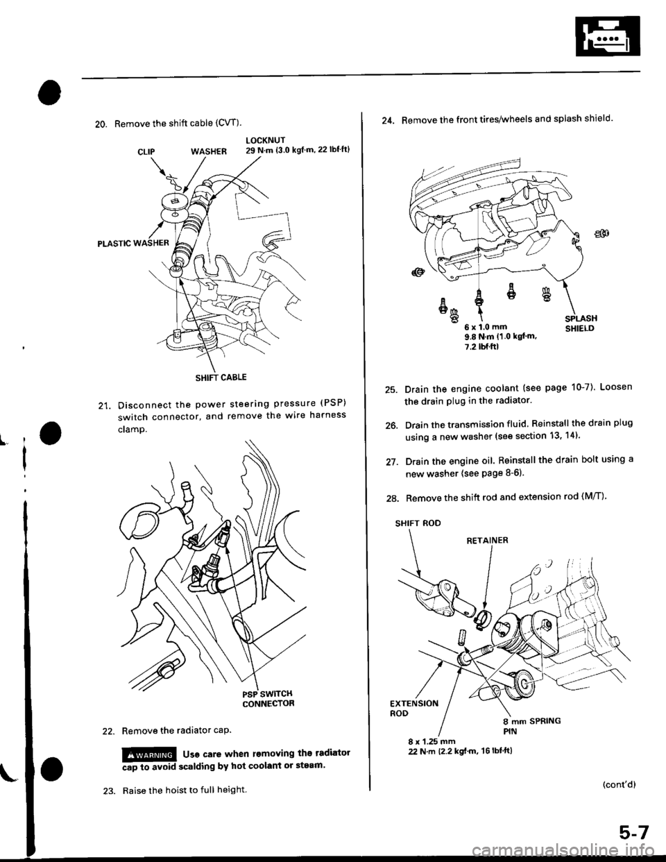
20. Remove the shift cable (CVT)
WASHER
Pt-Aslc
21. Disconnect the Power
switch connector, and
cramp.
LOCKNUT29 N.m {3.0 kgf m,22lbf'ft}
steering pressure (PSP)
remove the wire harness
CLIP
ll
I
Remove the radiator caP.
!!!@ usa care when l€moving the tadiator
Ap to avoid scalding by hot coolant or steam'
Raise the hoist to full height.
SHIFT CABLE
(cont'd)
25.
26.
27.
24. Remove the front tires/wheels and splash shield.
u x l.u mm SHIELD9.8Nm(1 0 kqt'm,
7.2lbf.ftl
Drain the engine coolant (see page 10-7). Loosen
the drain plug in the radiator.
Drain the transmission fluid Reinstall thedrainplug
using a new washer (see section 13, 14).
Drain the engine oil. Reinstall the drain bolt using a
new washer (see page 8-6).
28. Remove the shift rod and extension rod (M/T)
SHIFT ROD
EXTENSIONROD
8 x 1.25 mm22 N.m t2.2 kgf'm, 't6lbtft)
ER
6x1.0mm
Page 138 of 2189

Removal
Engine removal is not required for this procedure
!!!s@ Make sure iacks and salety stands are
f ta"eata"ea propetty and hoist brackets are attached to the
correct positions on the engine.
CAUTION:
. Use tender covels to avoid damaging painted sul-
faces.
o To avoid damage, unplug the wiling connectors
carefully while holding the connector portion to
avoid damage.
. To avoid damaging the cylinder head, wait until the
engine coolant temperature drops below 100"F
{38"C} before loossning the tetaining bolts.
NOTE:
o Mark all wiring and hoses to avoid misconnectlon
Also, be sure that they do not contact other wiring or
hoses, or interfere with other parts.
. Inspect the timing belt before removing the cylinder
h ead.
. Turnthe crankshaft pu lley so that the No. lpistonisat
top dead center (see Page 6-21)
'1. Disconnect the negative terminal from the battery'
Drain the engine coolant (see page'10-7).
a Remove the radiator cap to speed draining.
Remove the intake air duct and air cleaner housing
(see page 5 3).
Remove the mounting bolt and lock bolt. then
remove the power steering (P/S) pump belt and
pump (see page 5'5).
Loosen the idler pulley center nut and adjusting
bolt' then remove the air conditioning (A'lc) com-
pressor belt (see Page 5-6).
Loosen the mounting nut and lock bolt. then
remove the alternator belt (see page 6-19).
Remove the P/S pump bracket (see page 5-12).
3.
4.
2.
6.
1.
8. Remove the throttle cable by loosening the locknut,
then slip the cable end out of the throttle linkage
NOTE:
. Take care not to bend the cable when removing it
Always replace any kinked cable with a new one
. Adjust the throttle cable when installing (see sec-
tion 1 1).
D16Y7 engine:
Dl6Y5, Dl6Y8 engines:
THFOTTLECABLE
(cont'd)
6-27
LOCKNUT
CABLE
Page 158 of 2189
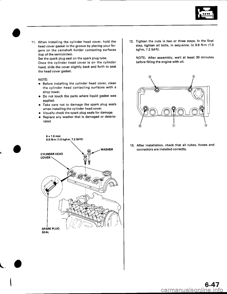
11. When installing the cylinder head cover, hold the
head cover gasket in the groove by placing your fin-
gers on the camshaft holder contacting surfaces
(top of the semicircles)
Set the spark plug seal on the spark plug tube.
Once the cylinder head cover is on the cylinder
head, slide the cover slightly back and forth to seat
the head cover gasket.
NOTE:
. Before installing the cylinder head cover, clean
the cylinder head contacting surfaces with a
shop towel.
. Do not touch the parts where liquid gasket was
aDolied.
. Take care not to damage the spark plug seals
when installing the cylinder head cover,
. Visually check the spark plug seals for damage.
. Replace any washer that is damaged or deterio-
rated.
6x1.0mm9.8 N.m 11.0 ksf.m,7.2lbf ftl
\g-----*o""t'Ptl
veEE
\_
6-47
12. Tighten the nuts in two or thre€ steps. In the final
step, tighten all bolts, in sequence, to 9 8 N'm (1.0
kgf.m, 7.2 lbf.ft).
NOTE: After assemblv, wait at least 30 minutes
before filling the engine with oil
After installation, check that all tubes, hosss and
connectors are installed correctlY
1?
Page 177 of 2189
Removal
Engine removal is not required for this procedure.
!@@ Make sure jacks and safety stands are placed
properly and hoist brackels are attached to correst posi-
tion on the engine,
CAUTION:
o Use fender covers to avoid damaging painted sur-
faces.
To avoid damage, unplug the wiling connectors
carelully while holding the connector portion.
To avoid damaging the cylinder head, wait until the
engine coolant temperature drops below 100"F {38'Cl
before loosening the retaining bolt.
NOTE:
. Unspecified items are common.
. Mark all wiring and hoses to avoid misconnection.
AIso, be sure that they do not contact other wiring or
hoses or interfere with other parts.
o Inspect the timing belt before removing the cylinder
n eao.
. Turn the crankshaft pulley so that the No. 1 piston is
at top dead center (see page 6-64).
1. Disconnect the negative terminal from the battery.
Drain the engine coolant {see page 10-7).
. Remove the radiator cap to speed draining.
Remove the strut brace (see page 5-2).
Remove the intake air duct and air cleaner housing
(see page 5-3).
Remove the adjusting bolt and mounting bolt, then
remove the power steering (P/S) pump belt and pump
(see page 5 5).
2.
3.
4.
\
ADJUSTING
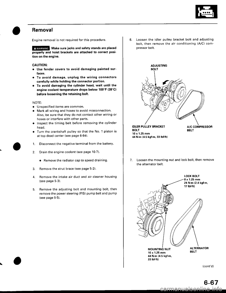
6. Loosen the idler pulley bracket bolt and adjusting
bolt, then remove the air conditioning (A/C) com-
pressor belt.
IDLER PULLEY BRACKETBOLT10 x 1.25 mm44 N.m {4.5 kg,l.m, 33 lbt.ft}
7. Loosen the mounting nut and lock bolt, then remove
the alternator belt.
LOCK BOLT8 x 1.25 mm24 N.m {2.4 kgf.m,17 tbtftl
ALTERNATORBELT10 x 1.25 mm,l,l N.m {4.5 kgf.m,33 tbf.ft,
(cont'd)
6-67
Page 196 of 2189
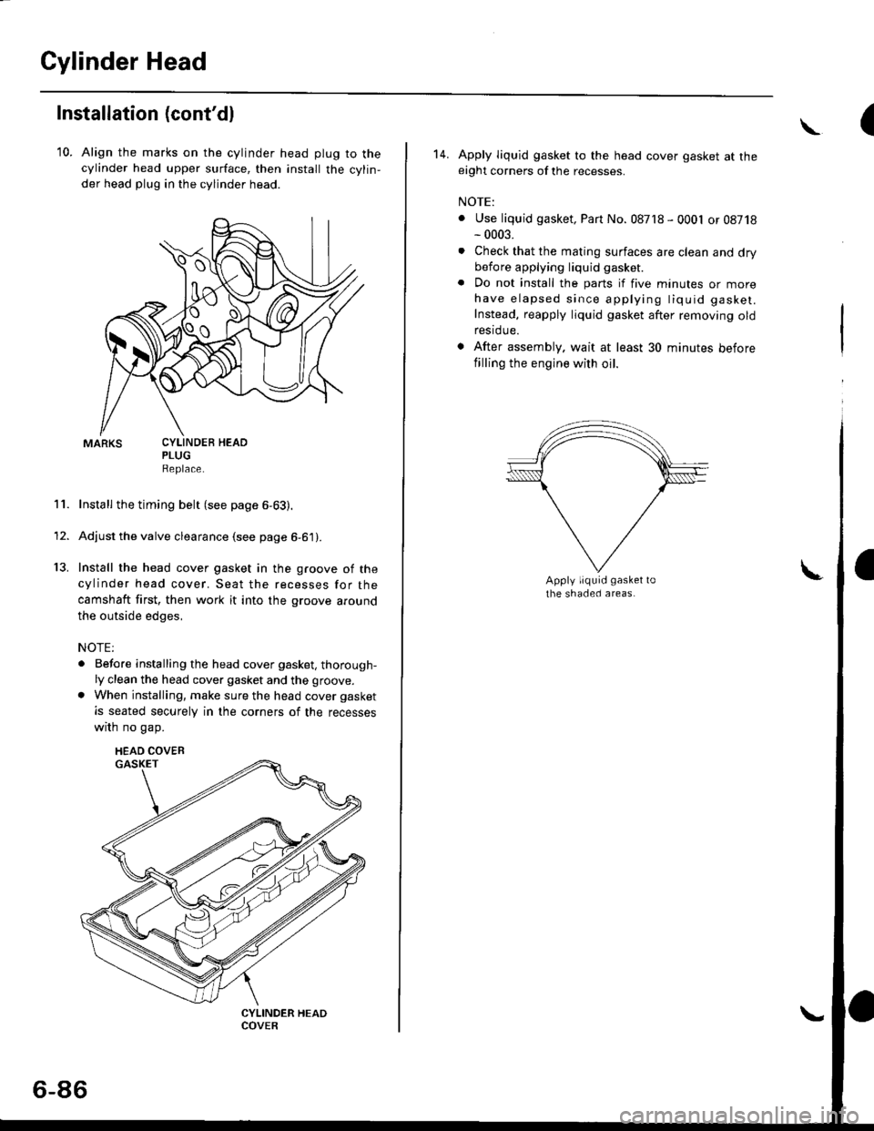
Cylinder Head
Installation (cont'dl
10. Align the marks on the cylinder head plug to thecylinder head upper surface, then install the cylin,
der head plug in the cylinder head.
PLUGReplace.
Install the timing belt (see page 6-63).
Adjust the valve clearance (see page 6-61).
Install the head cover gasket in the groove of the
cylinder head cover. Seat the recesses for the
camshaft first, then work it into the groove around
the outside edges,
NOTE:
. Before installing the head cover gasket, thorough-ly clean the head cover gasket and the groove.
. When installing, make sure the head cover gasket
is seated securely in the corners of the recesses
wrrn no gap.
11.
13.
1'
CYLINDEB HEAD
HEAD COVEB
6-86
(\
14. Apply liquid gasket to the head cover gasket at theeight corners of the recesses.
NOTE:
. Use liquid gasket, Part No. 08718 - 0001 or 08718- 0003.
. Check that the mating surfaces are clean and drybefore applying liquid gasket
. Do not install the parts if five minutes or morehave elapsed since applying tiquid gasket.
Instead, reapply liquid gasket after removing oldrestdue.
. After assembly. wait at least 30 minutes before
filling the engine with oil.
Page 489 of 2189

ldle Control System
ldle Speed Setting
Inspection/Adiustmenl
'96, '97 Dl6Y5. '96 - 00 Dl5Y8 sngine with M/T
NOTE:
. Before setting the idle speed, check the following
items:- The MIL has not been reported on.- lgnition timing- Spark plugs- Air cleaner- PCV system
o (Canada) Pull the parking brake lever up. Start the
engine, then check that the headlights are off.
1. Start the engine. Hold the engine at 3.000 rpm withno load (taansmission in neutral) until the radiatorfan comes on, then let it idle.
2. Connect a tachometer.
3. Disconnect the IAC valve connector.
4.lf the engine stalls, restart the engine with the accel-
erator pedal slightly depressed. Stabilize the rpm at1,000, then slowly release the pedal until the engineidles.
Check idling in no-load conditionsr headlights. blowerfan. rear defogger, radiator fan, and air conditioner
are not operating.
ldle spsed should be:
450 1 50 rpm
11-220
Adjust the idle speed, if necessary, by removing thecap and turning the idle adjusting screw.
NOTE; After adjusting the idle speed in this step,recheck the ignition timing (see section 23).
lf it is out of spec, go back to step 4.
IDLE
6. Turn the ignition switch OFF.
7. Reconnect the 2P connector on the IAC valve, then
do the ECM reset procedure.
8. Restart and idle the engine with no-load conditionsfor one minute, then check the idle speed.
NOTE: (Canada) Pull the parking brake lever up.Start the engine, then check that the headlights areoff.
ldle sp€sd should b€:
670 i 50 rpm IUSA)750 t 50 rpm {Canada}
9. ldle the engine tor one minute with headlights {Low)ON. and check the idle speed.
ldle speed should be:
750 :r 50 rpm
10. Turn the headlights off. ldle the engine for oneminute with heater fan switch at Hl and air conditioneron, then check the idle speed.
ldle speed should be:
810150 rpm
NOTE: lf the idle speed is not within specification,see Symptom Chan on page 11-84.
Page 490 of 2189

t
t
I
'96.'97 D16Y5 engine with CVT,'96 - 00 D16Y8 ongins
with A/T and'96 - 00 Dl6Y7 €ngine
Adiust the idle speed using a Honda PGM Tester if pos-
sible. lf not, use the following procedure:
NOTEI
. Leave the IAC valve connected
. Betore setting the idle speed. check the following
items:- The MIL has not been reported on'
- lgnition timing
- Spark Plugs- Air cleaner- PCV system
1. Connect a tachometer.
2. Start the engine. Hold the engine at 3,000 rpm wirh
no load (in Park or neutral) until the radiator fan
comes on, then let it idle.
3. Check the idle speed with no-load conditions: head-
iights, blower fan, rear defogger, radiator fan, and
air conditioner are not operatlng
ldl€ spoed should be:
USA:
D16Y5 engine with CVT, D16Y7 engine with A/T'
Dl6YB engine with A/T:
700 :r 50 rpm (in E or El Positionl
D16Y7 engine with M/T:
670 i 50 rpm
Canada:
Dl6Y8 sngin€, Dl6Y7 engins:
M/T750 t 50 rpm
NT750 1 50 rpm (in E or El Position)
Adjust the idle speed, if necessary, by removing the
cap and turning the idle adiusting screw 1/2-turn
clockwise or counterclockwise
D16Y5, D16Y8 engine:
IDLEADJUSTING
Dl6f, ongine:
NOTE: When you remove the ACL housing, do not
disconnect the IAT sensor connector
After turning the idle adjusting scrow 1/2-turn'
check the idle speed again. lf it is out of spec, turn
the idle adjusting screw 1/2-turn agaan'
NOTE: Do not turn the idle adjusting screw more
than 1/2-turn without checking the idle speed'
ldle the engine for one minute with heater fan
switch at Hl and air conditioner on, then check the
idle speed.
ldle speed should be:
M/T810150 rpm
A/T. CvT810 t 50 rpm (in El or E Position)
NOTE:
. Do not turn the idle adjusting screw when the air
conditioner is on.
. lf the idle speed is not within specification. see
Symptom Chart on page 11-84 (cont'd)
11-221