1999 HONDA CIVIC trans
[x] Cancel search: transPage 1424 of 2189
Mode Control SwitchPower Transistor
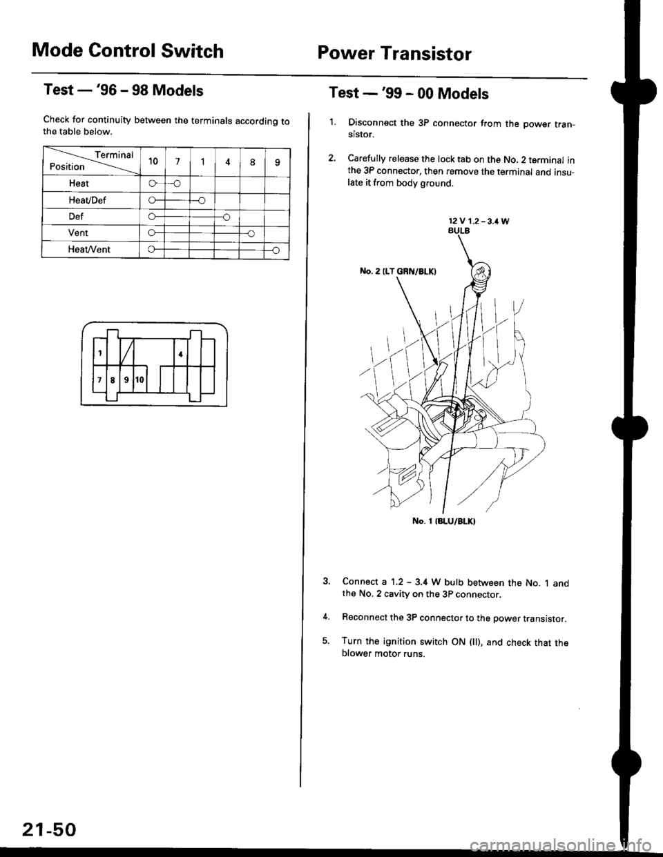
Test -'96 - 98 Models
Check for continuity between the terminals accordinq tothe table below.
Terminal
Position't071
Heato-o
HeaVDefo---o
Defo--o
VentG-o
HeaVVento--o
1
;l t
4
789
21-50
Test -'99 - 00 Models
1. Disconnsct the 3P connector from the oower tran-stsror.
2, Carefully release the lock tab on the No. 2 terminal inthe 3P connector, then remove the terminal and insu-late it from body glound.
Connect a 1.2 - 3.4 W bulb between the No. 1 andthe No. 2 cavity on the 3P connector.
Reconnect the 3P connector to the power translstor.
Turn the ignition switch ON fll), and check that theblower motor runs.
12V 1.2-3,1W
No. 1 laLU/aLK)
Page 1471 of 2189

l'f .
Electrical
Special Toofs .,....................,23-2
Troubleshooting
Tips and Precautions ..............,.................... . 23-3
Five-step Troubleshooting .............. ......... . . 23-5
wire color codes ..........,23-5
Schematic Symbols ........,................... . . .. .... 23-6
Relay and Control Unit Locations
Engine Compartment ...,..................... ... .. . 23'7
Dashboard ......................23-8
Dashboard/Door ......... 23-12*Airbags ................. ....... Section 24
Air Conditioning ......... Section 21
Aftelnator ..........."""" """ 23-112
Anti-lock Brake System {ABS) Section 19*A/T Gear Position Indicator .....................,. .... ... 23-149
Automatic Transmission Svstem .... . ....... Section 14
Batterv ......... . . . ... ...... .......23-91
Blower controls .. . ... Section 2l
Charging System ....'...........23'112
Connector ldentilication and Wire Harness
Routing .................. ......23'13
Cruise Control ............,........23-240
Dash Lights Brightness Controller ............. ....... 23-180
Fan controfs "" 23'126
Fuel PumD ........ . ........ section 11
Fuses/Refay ...............,..,,.. 23'62
PGM-FI Control System ......................,....... Section 1 1
*Gauges
Circuit Diagram ....,.,.......23-131
Fuef Gauge ...........'.'.......23-142
Gauge/lndicator .. . .. 23-129
Ground Distribution .. . 23-75
Heatei controls .. . ..... Section 21*Horn................. ...............23-196
*tgnition Switch ....................23-89
lgnition System .......,.... 23-102
*lntegrated Control Unit ....................................... 23-156
fnterlock System ,........ . . , ,23-144
Lighting System . . . .. ......... 23-161
Lights, Exterior
Back-up Lights ..'............23'171
Brake Lights .................. 23'174
Daytime Bunning Lights (Canadal ............... 23'166
Front Parking Lights ......,................ .'. .......... 23-167
Front Turn Signal Lights .......... . . ............ ..,.23-167
Headtights ....".'....-... ..... 23'167
High Mount Brake Light ...................... ... .23'179
License Plate Lights ...... 23'176
Taitfights ................ .......23'171
lnterior Lights ..-.......,, . 23-142
Moonroof ..,.................,........ 23-235
Power Distribution ....... . . .23-61
Power Door Locks .......,,,. .23'251
Power Mirrors ,..............,.,...23'206
Power Relays ....... . ...... . . .. 23-86
Power Windows ............,,....23-220
Rear Window Defogger .......................... . . ... . . 23-2OO
Spark Plugs . ..... . ........ .....23-111
Slarting System ................23-93*stereo Sound Svstem ,................. ..... ... . ... ,.,.,,23'147'Supplemental Restraint System (SRS) ... . Section 24
Turn Signal/Hazard Flasher System .......'.'....-... 23-173
*Undel-dash Fuse/Relay Box ............,.................. 23-85
vehicfe soeed sensor (VSSI """" ""' 23-140+Wipers/Washers .........,.,.,...23-214
NOTE: Unless otherwise specified, references to auto-
matic transmission (Mf) in this section include the CVT.
Page 1476 of 2189
Troubleshooting
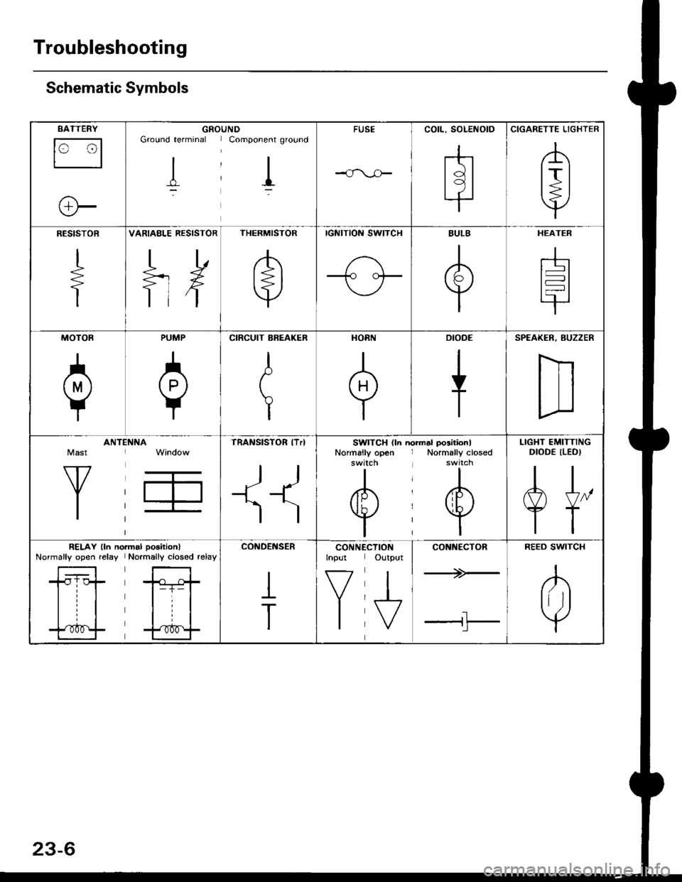
Schematic Symbols
BATTERY
E
@
GROGroLrnd terminal
II_d:
UNDComponent ground
II_..'-
FUSE
--cn-.e
COIL, SOLENOID
r{r
tql'|
CIGARETTE LIGHTER
A
lrl
P
RESISTOR
I
f
VARIAELE RESISTOR
ilH
THERMISTOR
c
IGNITION SWITCH
-fo o.t-
BULB
+
HEATEB
At-l
F
MOTOR
0
PUMP
H
CIRCUIT BREAKER
I
r
Yr
T
HORN
+
DIODE
+
SPEAKER, BUZZER
D
Mast
Y
ANTt:f\,NATRANSISTOR lTrl
II
SWITCH (ln niNormally open
I
/F\t tL I\Y/
I
rrdal positionlNormally closed'*i."n
@
I
LIGHT EMITTINGDIODE ILEDI
A+,
TT
RELAY lln noNormally opon relay
| ....--1'rl*r
til
t "t^f
fmal poaitionlNormally closed relay
ffl-+- |
lrl
lrl
fff
CONDENSER
I
T
CONNTInput
V
I
:CTIONOutput
J
CONNECTOR
*>-
'l!
REED SWITCH
A
tftl
Y
Page 1484 of 2189
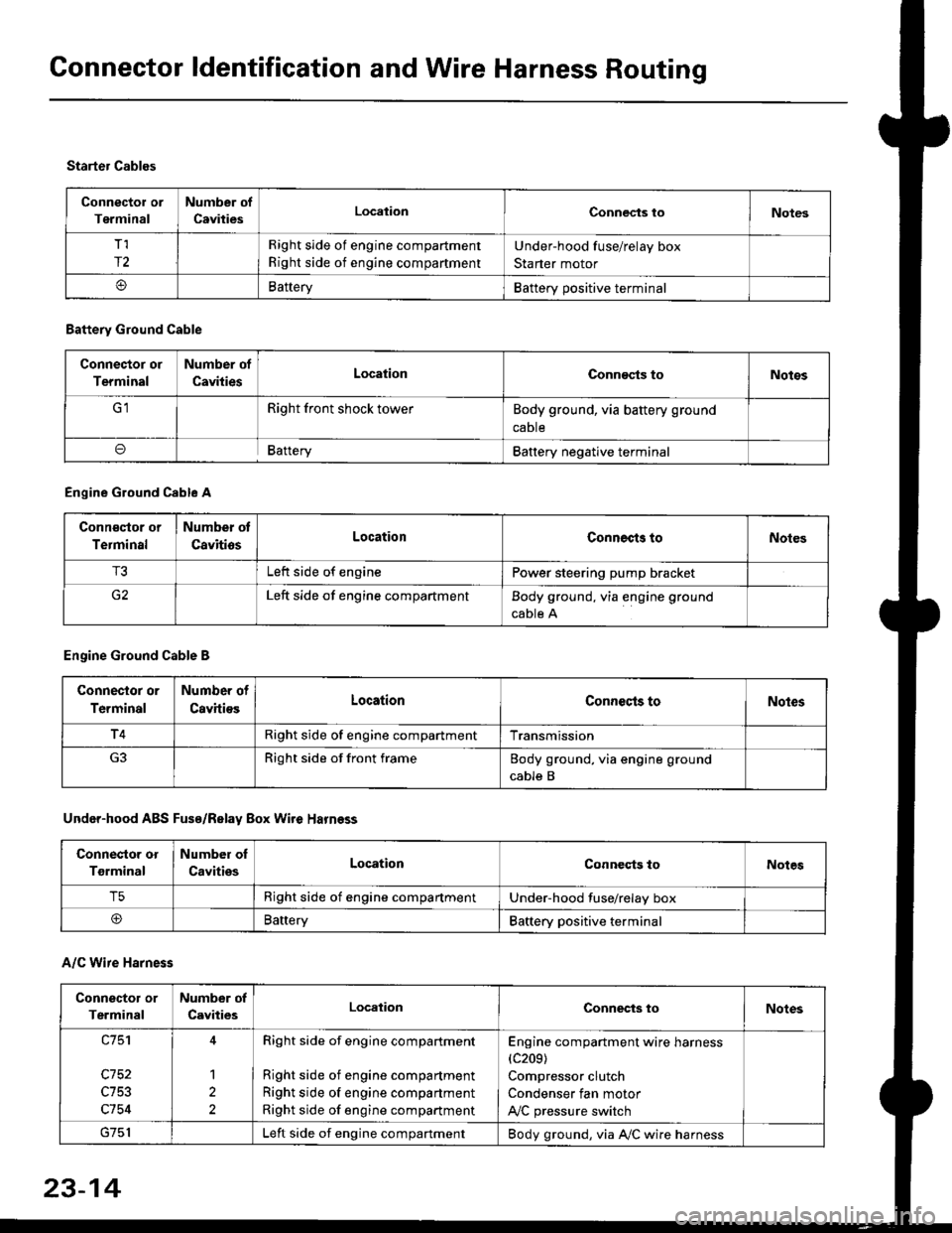
Connector ldentification and Wire Harness Routing
Connector or
Terminal
Number of
CavitiesLocalionConnec{s toNotes
T,I
r2
Right side of engine compartment
Right side of engine compartment
Under-hood fuse/relay box
Starter motor
BatteryBattery positive terminal
Starter Cables
A/C Wire Harness
Battery Ground Cable
Connector or
Terminal
Number of
CavitiesLocationConn€cts toNotos
Right front shock towerBody ground, via battery ground
caDte
oBafteryBattery negative terminal
Engine Ground Cable A
Conn€qtor or
Terminal
Number ot
CavitiosLocationConnects toNoles
T3Left side of enginePower steering pump bracket
G2Left side of engine compartmentBody ground, via engine ground
cable A
Engine Ground Cable B
Connector or
Terminal
Number of
CavitiesLocationConnecls toNoles
T4Right side of engine compartmentTransmission
Right side of front frameBody ground, via engine ground
cable B
Under-hood ABS Fusa/Relay Box Wire Harness
Connector or
Tgrminal
Number oI
CavitiesLocationConneqts toNotes
T5Right side of engine compartmentUnder-hood fuse/relay box
@BaneryBattery positive terminal
Connector or
Terminal
Number of
CavitiesLocationConnects toNotes
c753
c754
1
2
Right side of engine compartment
Right side of engine compartment
Right side of engine compartment
Right side of engine compartment
Engine compartment wire harness(c209)
Compressor clutch
Condenser fan motor
A,/C pressure switch
Left side of engine compartmentBody ground, via A,/C wire harness
23-14
Page 1502 of 2189
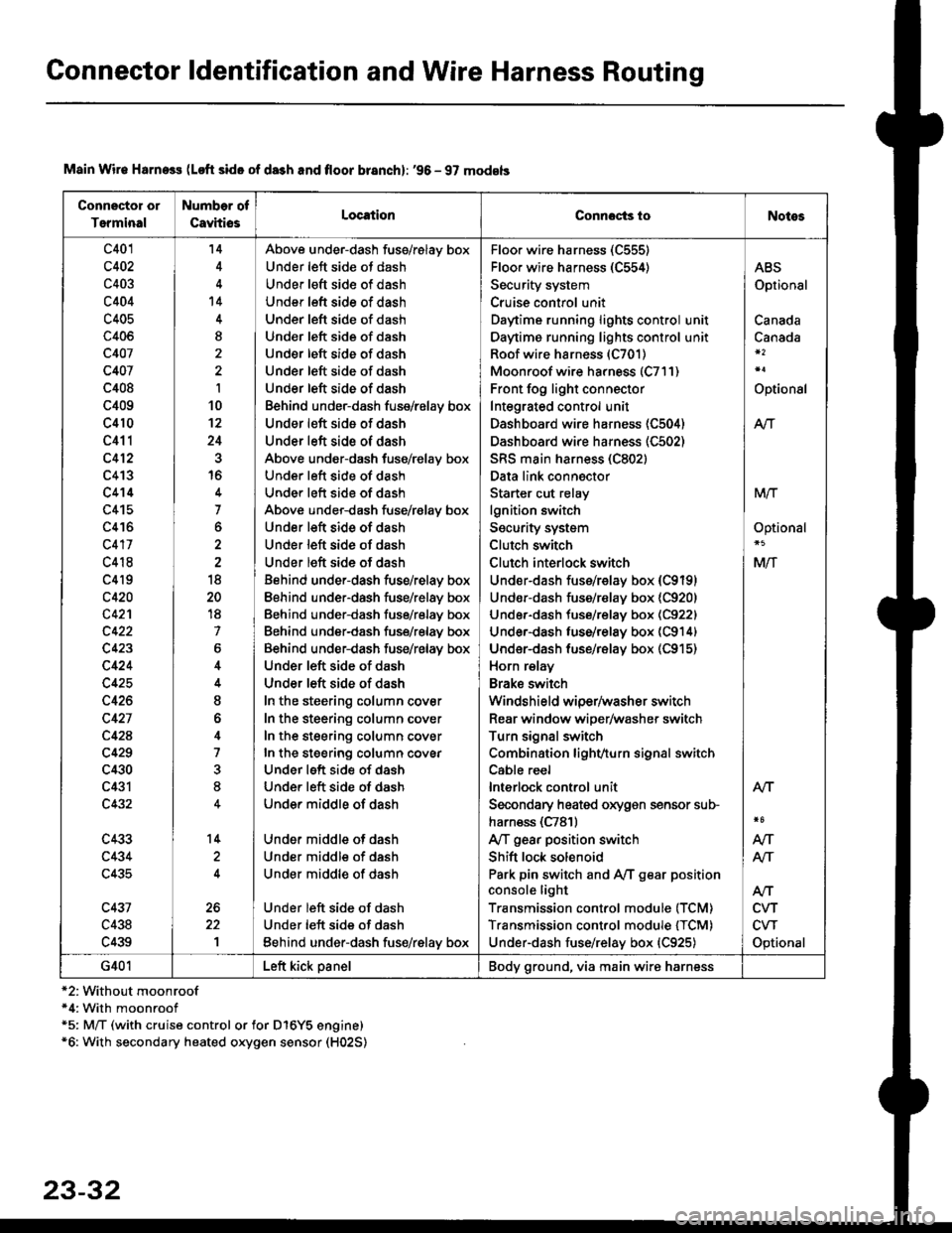
Connector ldentification and Wire Harness Routing
Connector or
Terminal
Number of
CavhiosLocationConnocts ioNotes
c401
c402
c403
c404
c405
c406
c407
c407
c408
c409
c410
c411
c412
c413
c414
c415
c416
c417
c418
c4l9
c420
c42'l
c423
c424
c425
c426
c427
c42A
c429
c430
c431
c432
c433
c434
c435
c431
c438
c439
'14
't4
I
I
10't2
24
16
7
o
18
20
18
7
6
I
o
4
7
8
14
1
Above under-dash fuss/relay box
Under left side ot dash
Under left sid€ of dash
Under left side of dash
Under left side of dash
Und€r left side of dash
Under left side of dash
Under left side of dash
Under left side of dash
Behind under-dash fuse/relay box
Under left side of dash
Under left side of dash
Above under-dash fuse/relay box
Under left side of dash
Under left side of dash
Above under-dash fuse/r€lay box
Under left side of dash
Under left side of dash
Under left side of dash
Behind under-dash fuse/relay box
Eehind under-dash fuse/relay box
Behind under-dash fuse/relay box
Behind under-dash fuse/relay box
Behind under-dash fuse/relay box
Under left side of dash
Under left side of dash
In the steering column cover
In the steering column cover
In the steering column cover
In the steering column covEr
Under left side of dash
Under left side of dash
Under middle of dash
Under middle of dash
Under middle of dash
Under middle of dash
Under left side of dash
Under left side of dash
Eehind under-dash fus€/relay box
Floo. wire harness (C555)
Floor wire harness (C554)
Security system
Cruise control unit
Daytime running lights control unit
Daytime running lights control unit
Roof wire harness (C701)
Moonroof wire harness (C7l1)
Front fog light connector
Integrated control unit
Dashboard wire harness (C504)
Dashboard wire harness (C502)
SRS main harness (C802)
Data link connector
Starter cut relay
lgnition switch
Security system
Clutch switch
Clutch interlock switch
Under-dash fuss/relay box (C9191
Undor-dash fuse/r€lay box {C920)
Under-dash tuse/relay box (C922)
Under-dash luse/relay box (C914)
Under-dash fuse/rBlay box (C915)
Horn relay
Brake swilch
Windshield wiper/washer switch
Rear window wiper/washer switch
Turn signal switch
Combination lighvturn signal switch
Cable reel
lnterlock control unit
Secondary heated oxygen sensor sub-
harn€ss (C781)
Ay'T gear position switch
Shift lock solenoid
Park pin switch and Ay'T gear position
console light
Transmission control module (TCM)
Transmission control module {TCM)
Under-dash fuse/relay box {C925)
ABS
Optional
Canada
Canada
Optional
Atr
MTT
Optional
Mlf
NT
Atf
CVT
CVT
Optional
AN
Atr
G401Left kick panelBody ground, via main wire harness
Main Wir€ Harness (Loft side of da3h and floor branch): '96 - 97 models
*2:Without moonroof*4: With moonroof*5: M/T (with cruise control or for D16Y5 engine)*6: With secondary heated oxygen sensor (H02S)
23-32
Page 1504 of 2189
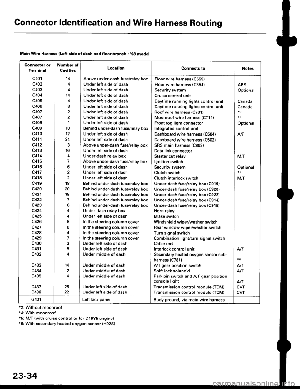
Connector ldentification and Wire Harness Routing
Connoctor or
Tgrminal
Number of
CavitiesLocationConneqts toNot€s
c401
c402
c403
c404
c405
c406
c407
c407
c408
c409
c410
c411
c4't2
c413
c414
c415
c416
c417
c418
c419
c420
c421
c422
c423
c424
c425
c426
c427
c428
c429
c430
c431
c432
c433
c434
c435
c437
c438
't4
l4
8,
1
10
12
24
7
6
18
20
18
7
6
8
7
8
14
2
Above under-dash fuse/relay box
Under left side of dash
Under left side of dash
Under left side of dash
Under left side of dash
Under left side of dash
Under left side of dash
Under left side of dash
Under left side of dash
Behind under-dash fuss/relay box
Under left side of dash
Under left side of dash
Above under-dash fuse/relay box
Under left side of dash
Under-dash relay box
Above under-dash fuse/relay box
Under left side of dash
Under left side of dash
Under left side of dash
Eehind under-dash fuse/relay box
Behind under-dash fuse/relay box
Behind under-dash fuse/relay box
Behind under-dash fuse/rslay box
Behind under-dash fuse/relay box
Under-dash relay box
Under left side of dash
In the steering column cover
In the steering column cover
In the steering column cover
In the steering column cover
Under left side of dash
Under left side of dash
Under middle of dash
Under middle of dash
Under middle of dash
Under middle of dash
Under left side of dash
Under left side of dash
Floor wire harness (C555)
Floor wire harness (C554)
Security system
Cruise control unit
Daytime running lights control unit
Daytime running lights control unit
Roof wiro harness (C7011
Moonroof wire harness (C711)
Front fog light connector
Integrated control unit
Dashboard wire harness (C504)
Dashboard wire harness (C502)
SRS main harness (C802)
Data link connector
Starter cut relay
lgnition switch
Security system
Clutch switch
Clutch inlerlock switch
Under-dash fuse/relay box (C919)
Under-dash fuse/relay box (C920)
Under-dash fuse/relay box (C922)
Under-dash fuse/relay box (C914)
Under-dash fuse/relay box (C915)
Horn relay
Brake switch
Windshield wiper/washer switch
Rear window wiper/washer switch
Turn signal switch
Combination light/,turn signal switch
Cable reel
lnterlock control unit
Secondary heated orygen sensor sub-
harness (C781)
Ay'T gear position switch
Shift lock solenoid
Park pin switch and Aff gear position
console light
Transmission control module (TCMI
Transmission control module (TCM)
ABS
Optional
Canada
Canada
Optional
M
MIT
Optionsl
MlT
Alr
NT
NT
CVT
CVT
G401Left kick panelBody ground, via main wire harness
Main Wire Harn€ss {Left side ot dash and floor branchl: '98 model
*2: Without moonroof*4:With moonroof*5: M/T (with cruise control or for D16Y5 engine)*6: With secondary heated oxygen sensor (H02S)
23-34
Page 1529 of 2189
'
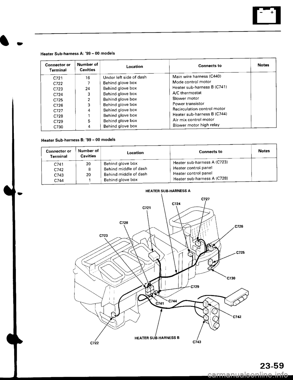
Heater Sub-harness A: '99 - 00 models
Connector or
Terminal
Number of
CavitiesLocationConnects toNotes
c721
c722
c723
c724
c725
c726
c727
c728
c729
c730
7
24
3
2
4
1
5
4
Under left side of dash
Behind glove box
Behind glove box
Behind glove box
Behind glove box
Behind glove box
Behind glove box
Behind glove box
Behind glove box
Behind glove box
Main wire harness (C440)
Mode control motor
Heater sub-harness B (C741)
lilc thermostat
Blower motor
Power transistor
Recircuiation control motor
Heater sub-harness B (C744)
Air mix control motor
Blower motor high relaY
Heater Sub-harness B: '99 - 00 models
HEATER SUB.HARNESS A
Connector or
Terminal
Number of
CavitiesLocationConnects toNotes
c7 41
c'742
c143
c744
20
8
20
1
Behind glove box
Behind middie of dash
Behind middle of dash
Behind glove box
Heater sub-harness A (C723)
Heater control Panel
Heater control Panel
Heater sub-harness A (C728)
Page 1721 of 2189
Power Door Locks
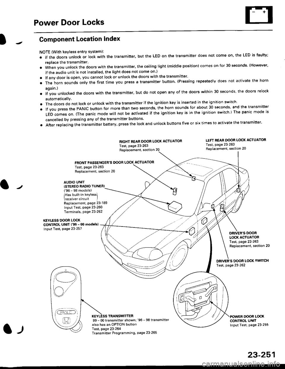
Component Location Index
NOTE (With keyless entry systeml:
. It the doors unlock or lock with the transmitter, but the LED on the transmitter does not come on, the LED is faulty;
replace the transmitter'
. when vou unlock the doors with the transmitter, the ceiling light (middle position) comes on for 30 seconds. (However,
if the audio unit is not installed, the light does not come on )
. lf any door is open, you cannot lock or unlockthe doors with the transmitter'
. The horn sounds only the first time you press a transmitter button. (Pressing repeatedly does not activate the horn
again.)
o lf vou unlocked the doors with the transmitter, but do not open any of the doors within 30 seconds, the doors relock
automatically.
. The doors do not lock or unlock with the transmitter if the ignition key is inserted in the ignition switch
. lf you press the PANIC button for more than two seconds, the horn sounds for about 30 seconds, and the transm'fer
LED comes on. (The panic mode will not be activated iJ the ignition key is in the ignition switch ) The panic mode is
cancelled by pressing any of the transmitter buttons'
o After replacing the transmitter battery, press the lock and unlock buttons five or six times to activate the transmitter'
Replacement, section 20
FRONT PASSENGER'S DOOR LOCK ACTUATOR
RIGHT REAR DOOR LOCK ACTUATOR
Test, page 23-263
I.IFT REAR DOOR LOCK ACTUATOR
Test, page 23 263Replacement, section 20
LOCK ACTUATORTest, page 23-263Replacement, section 20
ORIVER'S DOOR LOCK SWITCH
Test, page 23'262
DOOR L@XCONTROL UN]TInput Test, page 23 255
23-251
Test, page 23-263Replacement, section 20
AUDIO UNIT(STER€O RADIO TUNER)
{'96 - 98 models)
lHas built-in keylessl
eceiver circuit IReplacement, page 23-189
Input Test, page 23-260
Terminals, page 23-262
KEYLESS DOOR LOCKCONTROL UNIT l'99 - 00 modelsl
Input Test, Page 23-257
l-l
TRANSMITTER99 - 0O transmitter shown;'96 -98 transmifter
also has an OPTION buttonTest, page 23-264Transmitter Programming, page 23_265
Qi,,a/
/----
L(ru
i'.-8,-'l
/'-'6