Page 1200 of 2189
t-Operation
t
ABS Control Unit
Main Control
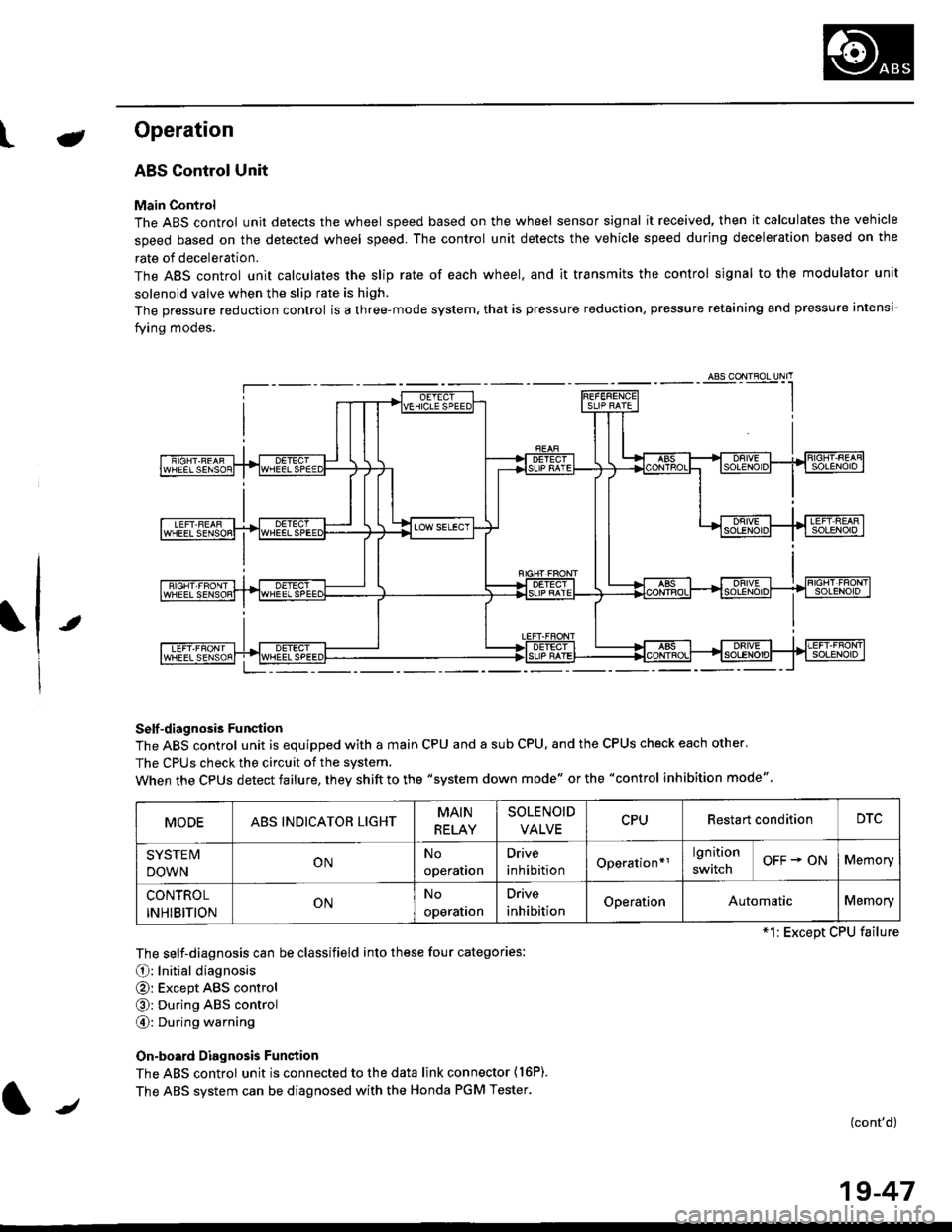
The ABS control unit detects the wheel speed based on the wheel sensor signal it received, then it calculates the vehicle
speed based on the detected wheel speed. The control unit detects the vehicle speed during deceleration based on the
rate of deceleration.
The ABS control unit calculates the slip rate of each wheel. and it transmits the control signal to the modulator unit
solenoid valve when the slip rate is high.
The pressure reduction control is a three-mode system, that is pressure reduction, pressure retaining and pressure intensi-
fying modes.
Self -diagnosis Funqtion
The ABS control unit is equipped with a main CPU and a sub CPU, and the CPUS check each other'
The CPUs check the circuit of the svstem.
When the CPUS detect failure, they shift to the "system down mode" or the "control inhibition mode"
The self-diagnosis can be classifield into these four categories:
O: Initial diagnosis
@: Except ABS control
@: During ABS control
@: During warning
On-board Diagnosis Funstion
The ABS control unit is connected to the data link connector {16P).
The ABS system can be diagnosed with the Honda PGM Tester.
(cont'd)
MODEABS INDICATOR LIGHTMAIN
RELAY
SOLENOID
VALVECPURestart conditionDTC
SYSTE IV
DOWNONNo
operation
Drive
inhibitionOperation*rlgnition
switchOFF + ONMemory
CONTROL
INHIBITIONONNo
operalron
Drive
inhibitionOperationAutomaticMemory
*1: Except CPU failure
/
19-47
Page 1375 of 2189
Heater
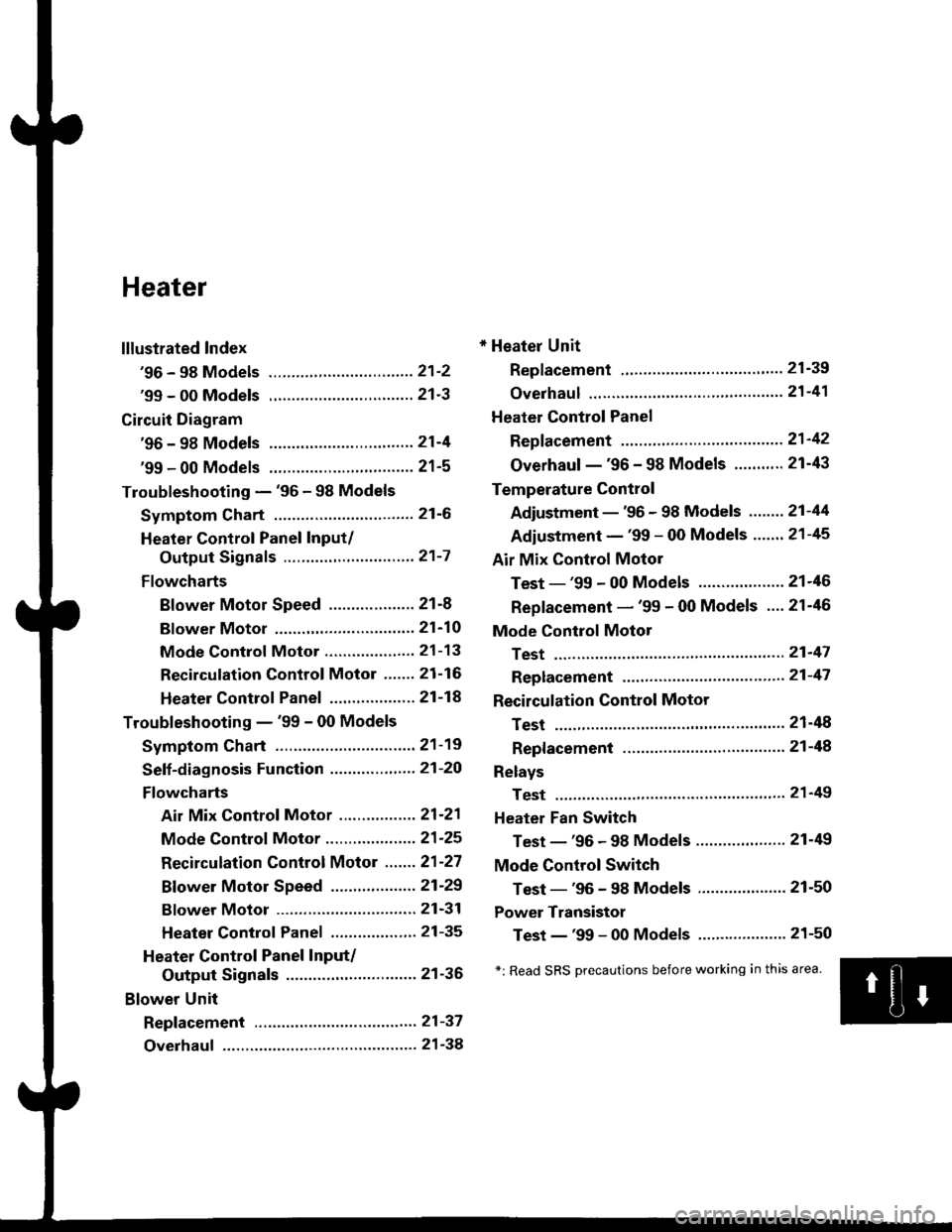
lllustrated Index
'96 - 98 Models ................................ 21'2
'99 - 00 Models ................................ 21'3
Circuit Diagram
'96 - 98 Models .....21-4
'99 - 00 Models ................................ 21-5
Troubleshooting - '96 - 98 Models
Symptom Chart ............................... 21-6
Heater Control Panel Input/
Output Signals ..............,.............. 21-7
Flowcharts
Blower Motor Speed ................... 21-8
Bf ower Motor ,...21'10
Mode Control Motor ............... ,.'.' 21-13
Recirculation control Motor ....... 21-16
Heater Control Panel ................ ... 21 -14
Troubleshooting - '99 - 00 Models
Symptom Chart ............................... 21-19
Seff-diagnosis Function ............,,,.... 21-20
Flowcharts
Air Mix Control Motor ......,.......... 21-21
Mode Control Motor ............... ..... 21 -25
Recirculation Control Motor ....... 21-27
Bf ower Motor Speed .............. .....21'29
Bf ower Motor ....21-31
Heater Control Panel ................,.. 21-35
Heater Control Panel Input/
Output Signals ............................. 21-36
Blower Unit
Repf acement .........21-37
Overhaul ................ 21-38
* Heater Unit
Replacement ....'....21-39
overhaul """" """' 21-4'l
Heater Control Panel
Repfacement .........21'42
Overhaul -'96 - 98 Models ........... 21-43
Temperature Control
Adjustment - '96 - 98 Models """" 21-44
Adiustment - '99 - 00 Models .......21-45
Air Mix Control Motor
Test - '99 - 00 Models ...........' .......21'46
Replacement - '99 - 00 Models ....21'46
Mode Control Motol
Test ................, .,...'.21'47
Replacement '.'."...21-47
Recirculation Control Motor
Test ................. .......21-48
Repf acement ......." 21-48
Relays
Test ................. .......2'l-49
Heater Fan Switch
Test - '96 - 98 Models ............. .......21-49
Mode Control Switch
Test -'96 - 98 Models ..........."....... 21-50
Power Transistor
Test - '99 - 00 Models ....'........ ....".21-50
*: Read SRS Drecautions before working in this area.
Page 1377 of 2189
'99 - 00 Models
SRS components are located in this area, Review the SRS component locations, precautions, and procedures in the SRS
section (24) betore perfoming repairs or service.
HEATER UNITReplacement, page 21'39
Overhaul, page 21-41
BLOWEB UNITReplacement, page 21-37Overhaul, page 21 38
HEATER FANswtTcH
RECIRCULATIONCONTROL MOTORTest, page 21-48Beplacement, page 21-48
AIR MIX CONTROL MOTOBTest, page 21-46Replacement, page 21 46
BLOWERTest, page 21-49
POWER TRANSISTORTest, page 21 50
HIGH RELAY
MODE CONTROLDIALHEATER VALVE CABLEAdjustment, page 21 45TEMPERATURE CONTROLDIALAdjustment, page 21-45
REAR WINDOWDEFOGGERswtrcHSee section 23MODEMOTORTest, page 21 47Replacement, page 2 l-47A/C SWTTCH
lwith A/cl
CONTROL SWITCH
21-3
Page 1403 of 2189
BIower Motor Speed
To page 21 30
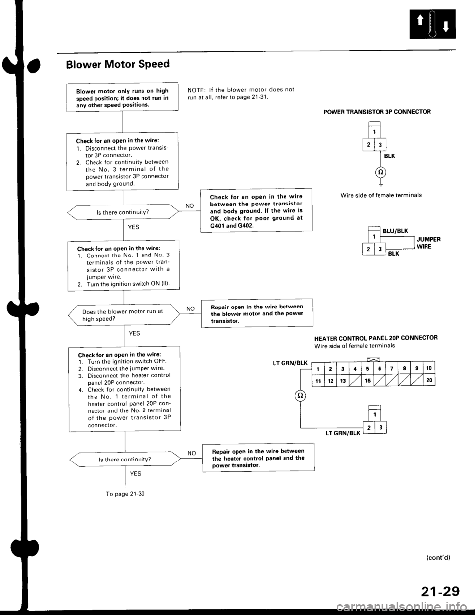
NOTE: lf the blower motor does not
run at all, refer to page 21-31.
POWEB TRANSISTOR 3P CONNECTOR
BLK
Wire side ol female terminals
JUMPERWIRE
HEATER CONTROL PANEL 2OP CONNECTOR
Wire side of female terminals
LT GRN/8LK
(cont'd)
21-29
Blower motor only runs on high
speed position; it does not run in
any other speed Positions
Check for an open in lhe wire:
1. Disconnect the power transis
tor 3P connector,2. Check for continuity between
the No. 3 terminal of thepower transistor 3P connector
and body ground.
Check tor an open in the wire
between the Power ttansistor
and body gtound. lf the wire is
OK, check for poor ground at
G401 and G402.
ls there continuity?
Check tor an open in the wire:
1. Connect the No. 1 and No 3
terminals of the Power tran_
sistor 3P connector wlth ajumper wire.2. Turn the ignition switch ON {ll)
Repair open in the wire belweenthe blower motor and the Powettranststor.
Check tor an open in the wire:
1. Turn the ignition switch OFF
2. Disconnect the iumPer wire.
3. Disconnect the heater controlpanel 20P connector.4. Check for continuity between
the No. 1 terminal of the
heater control panel 20P con-
nector and the No. 2 terminal
of the Power transistor 3P
Repair open in the wire between
the heater control Panel and tho
oower transistor,ls there continurty)
3
o
Page 1404 of 2189
Troubleshooting -'99 - 00 Models
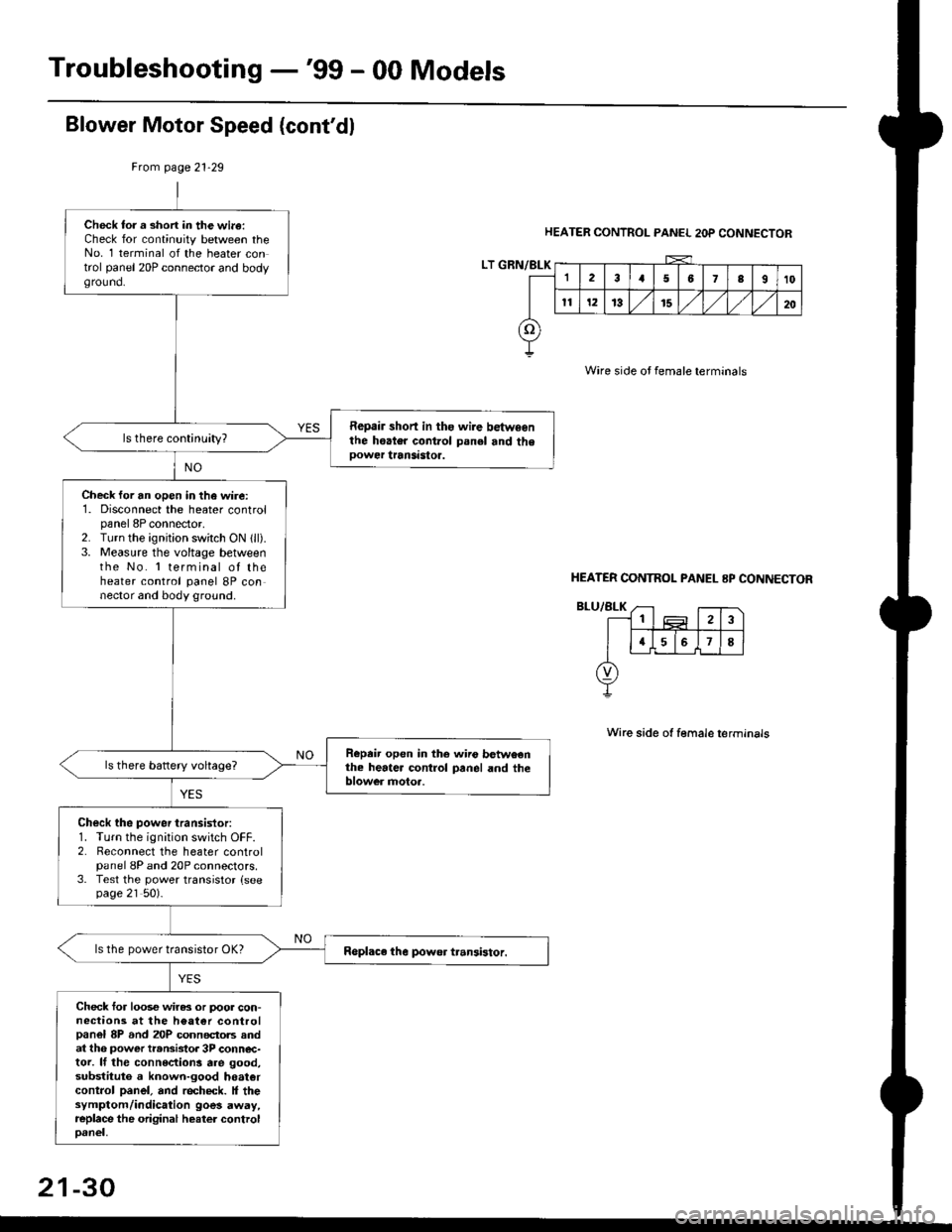
Blower Motor Speed (cont'dl
HEATER CONTROL PANEL 2OP CONNECTOR
Wire side oJ female terminals
Wire side ot female terminals
Frcm page 21.29
LT GRN/BLK
Check tor a short in the wi.a:Check for continuity between theNo. 1 terminal of the heater control panel 20P connector and bodyground.
Repair short in ths wire betwsenthe hoater control panel and theoower transastoa.
Check for an open in the wire:1. Disconnect the heater controlpanel 8P connector,2. Turn the ignjtion switch ON 1ll).3. Measure the voltage betweenthe No. 'l terminal of theheater control panel 8P connector and body ground.
Repeir open in the wiio betweenthe heater control panel and theblower motoa.
Check the power transistor:1. Turn the ignition switch OFF.2. Reconnect the heater controlpanel 8P and 20P connectors.3. Test the power transistor {seepage 21 50).
ls the power transistor OK?
Check for loos€ wiras or poor con-nections at the h€at€r controlpanel 8P and 20P connectols andat th6 power transistor 3P conn€c-tor. lf the connections are good,substituto a known-good hoatercontrol panel, and recheck. It thesymptom/indication goes away,replace the original heater controloanel,
HEATER CONTNOL PANEL 8P CONNECTOR
21-30
Page 1410 of 2189
Troubleshooting -'99 - 00 Models
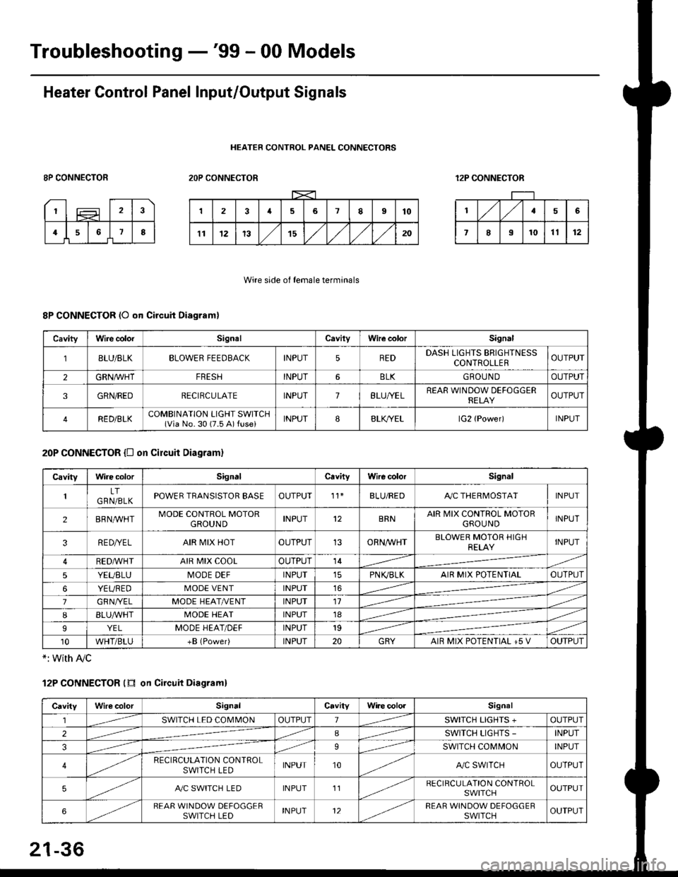
Heater Control Panel Input/Output Signals
HEATER CONTROL PANEL CONNECTORS
8P CONNECTOR2OP CONNECTOR12P CONNECTOR
Wire side of female terminals
8P CONNECTOR (O qn Circuit Diagram)
20P CONNECTOR {D on circuit Diagram}
*: with Ay'c
12P CONNECTOR (tr on Circuit Diagraml
CavityWire colorSignalCavilyWhe colorSignal
BLU/8LKBLOWER FEEDBACKINPUT5REDDASH LIGHTS BRIGHTNESSCONTROLLEROUTPUT
2GRN/lVHTFRESHINPUT6BLKGBOU N DOUTPUT
3GRN/REDRECIRCULATEINPUT7BLU/YELREAR WINDOW DEFOGGERRELAYOUTPUT
4RED/BLKCOMBINATION LIGHT SWITCH(Via No. 30 (7.5 A) fuse)INPUT88LfiELlG2 {Power)INPUT
CavityWire colorSignalCavityWire colorSignal
LTGRN/BLKPOWER TRANSISTOR EASEOUTPUT't1BLU/REDAy'C THERMOSTATINPUT
2BRNMHTMODE CONTROL MOTORGROUNDINPUT12BRNAIR MIX CONTROL MOTORGROU NDINPUT
3RE D/YELAIR MIX HOTOUTPUT13ORNAA/HTBLOWER MOTOR HIGHRELAYINPUT
RED,ryvHIAIR MIX COOLOUTPUT14
5YEUBLUMODE DEFINPUTPN K,/BLKAIR MIX POTENTIALOUTPUT
6YEUREDMODE VENTINPUT16
7GRNI/ELMODE HEAT/r'ENTINPUT11
IBLUAVHTMODE HEATINPUT18
9YELMODE HEAT/DEFINPUT19
10WHT/BLU+B (Power)INPUT20GRYAIR MIX POTENTIAL +5 VOUTPUT
CavityWilecolorSignalCavityWi.e cololSignal
lSWITCH LED COMMONOUTPUT1SWITCH LIGHTS +OUTPUT
2ISWITCH LIGHTS -INPUT
39SWITCH COMMONINPUT
4RECIRCULATION CONTROLSWITCH LEDINPUT10A,/C SWITCHOUTPUT
5A./C SWITCH LEDINPUT11RECIRCULATION CONTROLSWITCHOUTPUT
6REAR WINDOW DEFOGGERSWITCH LEDINPUT12REAR WINDOW DEFOGGEBSWITCHOUTPUT
21-36
Page 1411 of 2189
Blower Unit
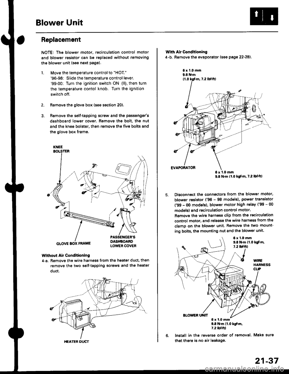
Replacement
NOTE: The blower motor, recirculation control motor
and blower resistor can bs replacsd without rsmoving
th€ blower unit (see neld Page).
1. Move the temperature control to "HOT."
'96-98: Slide the temperature control lever.'99-00: Turn the ignition switch ON (ll), then turn
the temperature contol knob. Turn the ignition
switch off,
Remove the glovs box (ses ssction 20),
R€move ths s6lf-tapping screw and ths passsng6r's
dashboard low€r cover. Removo the bolt, the nut
and the kn€e bolst€r, then remove the fiv€ bolts and
the glove box trame,
Without Air Condhioning
4-a. Remove the wiro harness from the h68t€r duct, then
remove the two self-tapping scrsws and the heatsr
duct.
KNEE
GLOVE BOX FRAME
HEATER DUCT
21-37
Wrth Air Conditioning
4-b. Removo th6 ev8porator (sss pago 22-28).
6x1.0m|n9.8 N'm
6x1.0mm9.8 N'm lt'o tgf'm, t.2 lb{'ttl
Disconnoct the connectors trom th€ blower motor,
blowor r6sistor {'96 - 98 models), power transiator
('99 - 0O modsls), blowor motor high telay ('99 - 00
models) and recirculation control motor.
R€mov€ ths wiro harnoss clip from tho recirculation
control motor, and release the wir6 harnsss from ths
clamo on the blowor unit. Remove the two mount-
ing bolts, tho mounting nut and ths blowor unit'
9.8 .m 11.0 tgfm,1.2 tblfrl
lnstall in ths reverso order of removal. Mako surs
that thsre is no air leaka96.
6x1.0mm9,t N'm 11.0lgi.m,7.2 tbf.fil
Page 1412 of 2189
Blower Unit
Overhaul
NOTE:
RECIRCULATIONCONTROL MOTORTest, page 21-48
aBefore reassembly. make sure that the recirculation control door and linkage move smoothly without binding.
When attaching the recirculation control motor, make sure its positioning will not allow the recirculation control door
to be pulled too far.
After aftaching the recirculation control motor, connect power and ground, and watch the movement of the recircula-
tion control door.
BLOWERTest, page 2'l 9{'96 - 98 modebl
POWER TRANSISTOR l'99 - 00 modeblTest, page 21-50
Test, page 21'10 ('96 98 models) orpage 21'31 ('99 00 models)
m
MOTOR
2134